WIFO WI-5000-T Operator's manual

WIFO-Anema B.V.
Hegebeintumerdyk 37 – 9172 GP Ferwert – Holland
Telefoon (0031) 518411318 – Telefax (0031) 518411563
www.wifo.nl – email: [email protected]
Manual and safety instructions
WI-5000-T/WI-5000-TS
Weighing equipment
Appendix WI-5000-T: Operators Manual “Digi-star EZ 400”
Appendix WI-5000-TS: Operators Manual “Risseeuw spreading computer”
GB
WI-5000-T WI-5000-TS


1
English
Table of contents
1. TO THE USER ...................................................................................................................................................................... 2
1.1 INTRODUCTION ...................................................................................................................................................................... 2
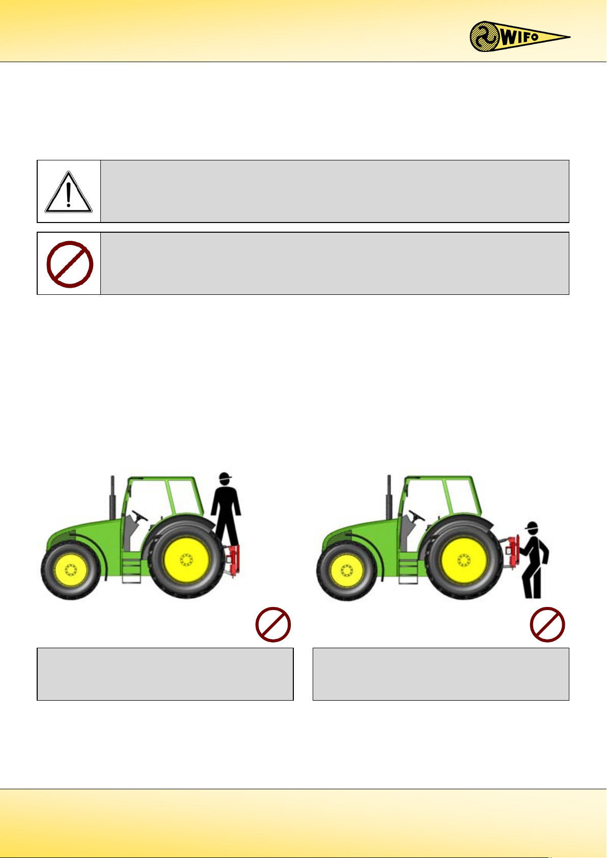
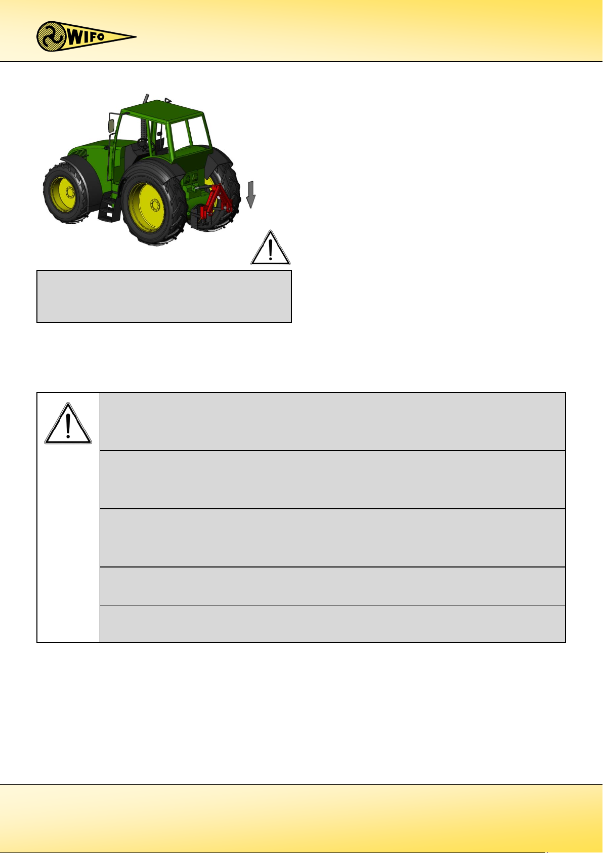
1.2 SAFETY PRECAUTIONS AND WARNINGS........................................................................................................................................ 3
1.2.1 Safety regulations..................................................................................................................................................... 3
1.2.2 Safety stickers and warning signs............................................................................................................................. 5
1.2.3 Placement of the safety stickers on the machine ..................................................................................................... 5
1.3 PURPOSE OF USE .................................................................................................................................................................... 6
1.4 LIABILITY............................................................................................................................................................................... 7
1.5 WARRANTY ........................................................................................................................................................................... 7
2. TECHNICAL DETAILS........................................................................................................................................................... 8
2.1 GENERAL TECHNICAL DATA...................................................................................................................................................... 8
2.2 WI-5000-T ......................................................................................................................................................................... 9
2.2.1 Parts list........................................................................................................................................................................ 9
2.2.2 Commencement of operation WI-5000-T.................................................................................................................... 10
2.3 WI-5000-TS ..................................................................................................................................................................... 11
2.3.1 Parts list...................................................................................................................................................................... 11
2.3.2 Commencement of operation WI-5000-TS.................................................................................................................. 12
2.4 ACCESSORIES/OPTIONAL EXTRAS.............................................................................................................................................. 13
2.4.1 Extension triangle for WI-5000-T/WI-5000-TS ........................................................................................................... 13
2.5 REPLACEMENT COMPONENTS.................................................................................................................................................. 13
3. FAULTS AND MAINTENANCE ........................................................................................................................................... 14
3.1 TROUBLESHOOTING.............................................................................................................................................................. 14
3.2 WORK TO BE CARRIED OUT BY THE USER ................................................................................................................................... 15
3.2.1 Calibrating the weighing equipment for WI-5000-T ............................................................................................... 15
3.2.2 Calibrating the weighing equipment for WI-5000-TS ............................................................................................. 16
3.2.3 Circuit testing weighing pins for WI-5000-T/WI-5000-TS ....................................................................................... 17
3.3 WORK TO BE CARRIED OUT BY A COMPETENT WELDER/MECHANIC ................................................................................................. 18
3.3.1 Instructions for welding an extension triangle to a machine...................................................................................... 18
3.3.2 Instructions for replacing a weighing pin.................................................................................................................... 18

2
1. To the user
1.1 Introduction
This manual gives information about the commencement of operation, use and maintenance of your newly
purchased WIFO weighing equipment. Also included in this manual are a number of safety instructions to create a
safe working environment.
WIFO-Anema B.V. continuously aims to improve its products. WIFO-Anema B.V. reserves the right to introduce any
changes and improvements deemed necessary without prior notice.
Please read the manual thoroughly and observe the safety procedures before putting the unit into operation.
Contact your dealer for any further questions or concerns you may have.
We hope you will enjoy working with your WIFO weighing equipment.
Keep this manual in a safe place for future reference!
WIFO-Anema B.V.
Dealer:
ATTENTION:
Carefully read this manual before you put the machine into operation and act upon all directions that are
given. This is to guarantee its safe, trouble-free operation.

3
1.2 Safety precautions and warnings
Please read this manual before you put the machine into operation for the first time, and observe the safety
instructions at all times. The most important instructions are marked with a symbol.
Any person in charge of the commencement of operation, the operation itself or the maintenance of the machine is
urged to carefully read and observe the following instructions.
1.2.1 Safety regulations
This symbol is used for all important actions that should not be carried out under any circumstances.
Carefully observe these prohibitions.
Do not allow anyone to hitch a ride.
Do not stand below the weighing equipment and stay
out of the working area of the built-on equipment. Be
mindful of falling goods.
This symbol is used for all important safety instructions throughout this manual. Carefully observe the
instructions and be very cautious.

4
Transport the load in the lowest possible position to
increase the stability of the vehicle.
Load the weighing equipment in a manner that goods are properly secured. Distribute the goods evenly.
Keep the centre of gravity close to the mounting frame and always between the measuring pins for accurate
reading. Make sure the weighing equipment is in a vertical position during the weighing process in order to
minimise inaccurate reading (+/- 1%).
Operate the weighing equipment and auxiliary equipment from the driver's seat only. Make sure the
operator has full view of the work to be carried out.
Park the transport vehicle with the weighing equipment in the lowest position. Make sure that unexpected
movements are ruled out if the combination is not being used. Place the weighing equipment on its front on
a flat, stable surface after having been uncoupled and put away.
Make sure the power cables cannot get jammed during the operation.
Make sure the weighing computer for controlling the weighing equipment is not mixed up with any other
operating equipment to prevent any inadvertent operation.

5
1.2.2 Safety stickers and warning signs
Several safety stickers have been put onto the machine. The meaning of the stickers on this machine is as follows:
1.2.3 Placement of the safety stickers on the machine
A safe working environment also requires personnel to be well-informed about the various safety stickers
on the machine. Be aware of the hazards they warn you to look out for.
Replace any loose, illegible or missing stickers.
Figure 1.2.1-Position of safety stickers for WI-5000-T/WI-5000-
TS
1
2
N.B.:
Please read the instructions from the manual prior to any maintenance to the
machine.
Turn off the engine and remove the key from the ignition for the time
maintenance on the machine is carried out!
1
Danger:
Always keep at a safe distance from the machine!
2

6
1.3 Purpose of use
WIFO weighing equipment can be used for weighing goods up to 5,000 kg. Forces up to 1,000 kg may be brought in
the horizontal plane of the weighing equipment.
WIFO weighing equipment is only to be used in combination with a tractor with a standard category II/III 3-point
power lift.
Do not use the WIFO weighing equipment for carrying people under any circumstances!
ATTENTION:
The lifting capacity of the tractor / telescopic handler / front-end loader must exceed the overall mass of the
weighing equipment and the load. The lifting capacity of the weighing equipment may not exceed 5,000 kg.
ATTENTION:
The weighing equipment may not be used in combination with e.g. excavators or mowers because of any
lateral and/or tensile forces. Remove the weighing equipment in such situations.

7
1.4 Liability
Any person working with or on the machine must have read this manual. The machine is to be used for its intended
purpose only.Included in the intended purpose are, among other things:
1. Work must be carried out in accordance with the directions and within the functional restrictions (e.g.
maximum hydraulic working pressure) as outlined in the regulations. Use only sound and appropriate tools.
2. Electric / electronic equipment and accessories (e.g. cables) must be treated in accordance with the general
accepted policy for using non-waterproof portable electric and electronic equipment, such as.:
a) Storing and keeping in a clean, dry environment away from rodents and the like; and
b) Protecting the equipment against severe, uncushioned shocks and water (precipitation).
3. Use only original or compatible spare parts. Such parts must be assembled as directed (e.g. by observing the
recommended tightening moments). Spare parts (as well as lubricants) are considered compatible only if
explicitly approved by WIFO or in the event that the customer is able to prove they possess the required
properties for the purpose(s) they are used.
4. Use only lubricants that meet the specifications as described in the directions.
5. Always observe the local regulations in terms of accident prevention, safety, traffic and transport.
6. Only trained personnel with knowledge of the possible hazards have permission to work with/on the
machine.
7. WIFO-Anema B.V. will assume no liability in any shape or form for losses or damage caused following
modifications to the machine, which have not been explicitly approved by WIFO.
1.5 Warranty
WIFO-Anema B.V. guarantees the soundness of its products in terms of materials used and/or structural defects.
However, in any event this warranty is limited to the free-of-charge replacement or repairs of the defect product, or
part thereof. WIFO-Anema B.V. assumes no liability for any loss or damage arising from faulty deliveries and/or the
breakdown of purchased goods before the warranty period has expired. The warranty period for this product is
twelve months.
Noncompliance with the rules and directions from this manual will be considered as serious negligence,
for the consequences of which WIFO-Anema B.V. accepts no liability whatsoever. In such cases, the user
will bear the full risk of his actions.
WIFO-Anema B.V. is continuously working on the improvement of its products. For that reason, WIFO-
Anema B.V. reserves the right to introduce any changes and improvements deemed necessary without
prior notice. However, it does not imply an obligation to make any such changes or improvements to
machines bought by customers in the past.

8
2. Technical details
2.1 General technical data
1In category II 3-point power lift / In category III 3-point power lift.
Extension details:
The tractor must have a standard category II/III 3-point power lift.
Optional extras:
-Extension triangle.
Model WI-5000-T WI-5000-TS
Measuring range Up to 5000 kg Up to 5000 kg
Measuring deviation +/- 1% +/- 1%
Display 10 grams – 100 kg (standard 1 kg) 10 grams – 100 kg (standard 1 kg)
Connection 12 Volt 12 Volt
Weight 90 kg 95 kg
Extension loss1 80 mm/120 mm 80 mm/120 mm
Table 2.1.1-Models of WIFO weighing equipment
ATTENTION:
Zero adjustment-setting and calibration have been realised by the manufacturer.

9
2.2 WI-5000-T
2.2.1 Parts list
No. Description Comments
1 Three-point frame
2 Carrier frame
3 Wire box
4 Weighing pin
5 Tops category I
6 Tops category II
7 Carrier pin category II
8 Spacers
9
Extension triangle
Accessory
10 Digi-Star weighing computer
11 Base plate for spreading computer
Table 2.2.1-Parts list for WI-5000-T

10
2.2.2 Commencement of operation WI-5000-T
The following description refers to the add-on unit for a tractor with a 3-point power lift:
1. Make sure the drawbars of the power lift of the tractor are at the same level.
2. Couple the 3-point weighing equipment to the category II/III 3-point power lift of the tractor. Use the spacer
sleeves to fill up the drawbars. Use good-quality locking clips.
3. Adjust the upper control arm to ensure the weighing equipment is in an absolute vertical position.
4. Only very little lateral play of the weighing equipment in the power lift is allowed. Make the adjustments via
the stabilizers of the power lift.
5. Attach the instrument with the extension triangle to the weighing equipment and secure it using the pin and
the spring clip.
Following the weighing equipment, the weighing computer can be installed:
1. Mount the weighing computer using the mounting plate in such a location that the tractor driver is able to
see and operate the weighing computer from his control post, without the risk of mixing it up with any other
controls.
2. Connect the 2-core power cable as follows: the red wire (+) goes to a fused, continuously live wire. The black
wire (-) goes to earth. When connecting the wires, make sure the connections are properly clean and dry.
Keep an eye on the correct voltage of the tractor and the weighing computer. The weighing computer runs
on 12 Volt.
The WIFO weighing equipment is now ready to be used.
Keep the sensor wire, from the weighing equipment to the weighing computer, at a fair distance
from live wires and the like, in order to prevent any incorrect readings. The operation of the
electronically controlled power lift could also end up deranged. Even a mobile phone call may have
an effect on the measuring data of the weighing computer.

11
2.3 WI-5000-TS
2.3.1 Parts list
No. Description Comments
1 Three-point frame
2 Carrier frame
3 Wire box
4 Weighing pin
5 Tops category I
6 Tops category II
7 Carrier pin category II
8 Spacers
9 Extension triangle Accessory
10 Risseeuw weighing/spreading computer
11 Base plate for spreading computer
12 Electric wire spindle
Table 2.3.1-Parts list for WI-5000-T

12
2.3.2 Commencement of operation WI-5000-TS
The following description refers to the add-on unit for a tractor with a 3-point power lift:
1. Check that the drawbars of the power lift of the tractor are at the same level.
2. Couple the 3-point weighing equipment to the category II/III 3-point power lift of the tractor. Use the spacer
sleeves to fill up the drawbars. Use good-quality locking clips.
3. Adjust the upper control arm to ensure the weighing equipment is in an absolute vertical position.
4. Only very little lateral play of the weighing equipment in the power lift is allowed. Make the adjustments via
the stabilizers of the power lift.
5. Attach the instrument with the extension triangle to the weighing equipment and secure it using the pin and
the spring clip.
Following the weighing equipment, the weighing/spreading computer can be installed:
1. Mount the weighing/spreading computer using the mounting plate in such a location that the tractor driver
is able to see and operate the weighing/spreading computer from his control post, without the risk of mixing
it up with any other controls.
2. Connect the 2-core power cable as follows: the red wire (+) goes to a fused, continuously live wire. The black
wire (-) goes to earth. When connecting the wires, make sure the connections are properly clean and dry.
Keep an eye on the correct voltage of the tractor and the weighing/spreading computer. The
weighing/spreading computer operates on 12 Volt.
The WIFO weighing equipment is now ready to be used.
Keep the sensor wire, from the weighing equipment to the weighing computer, at a fair distance
from live wires and the like, in order to prevent any incorrect readings. The operation of the
electronically controlled power lift could also end up deranged. Even a mobile phone call may have
an effect on the measuring data of the weighing computer.

13
2.4 Accessories/optional extras
2.4.1 Extension triangle for WI-5000-T/WI-5000-TS
Purpose of use:
A piece of equipment, such as a fertilizer spreader, must be fitted with an extension triangle to be attached to the
weighing machine.
Commencement of operation:
Operating instructions:
Make sure the carrier frame is in line with the extension triangle so that the pin fits through the hole in the extension
triangle and can be secured using the lock pin and the spring clip.
2.5 Replacement components
Model Description Part no.
All models Weighing pin 839005
Wire box 839023
Feeder 839025
WI-5000-T Digi-Star EZ-400 weighing computer 839021
WI-5000-TS Risseeuw weighing/spreading computer -
Table 2.5.1-Replacement components WIFO weighing equipment
ATTENTION:
Welding an extension triangle to a piece of equipment must be carried out by a professional
welder/mechanic.

14
3. Faults and maintenance
Make sure the weighing equipment is in the lowest position during maintenance. Prevent any inadvertent operation
of the weighing equipment during maintenance by turning the tractor engine off and taking the key from the
ignition.
3.1 Troubleshooting
For WI-5000-T: See “Digi-star EZ 400” operators manual.
For WI-5000-TS: See “Risseeuw spreading computer” operators manual.
Please contact your dealer for any further concerns you may have. He will be pleased to assist.
Warning:
Do not conduct any welding jobs on the weighing equipment to prevent damage to the weighing sensors.
Remove the weighing equipment during welding jobs on the tractor or machine.
ATTENTION:
When hosing down the machine, make sure not to aim for the cable inlet of the weighing pins to avoid
damage to the weighing pins as a result of moisture.
N.B.:
Please read the instructions from the manual prior to any maintenance to the
machine!
Turn off the engine and remove the key from the ignition for the time maintenance
on the machine is carried out!

15
3.2 Work to be carried out by the user
3.2.1 Calibrating the weighing equipment for WI-5000-T
1. Put the weighing trestle at zero via net gross and zero.
2. Then push and hold the net gross and on buttons simultaneously.
3. Hold the net gross button pushed down until calib appears on the screen.
4. Push the on button three times.
5. Put a heavy object, the weight of which is known, onto the weighing trestle. For the best results, calibrate
the computer with at least the heaviest load you will use.
6. Push the on button, and the value will start to blink.
7. Enter the correct weight (the calibration weight) via the net gross and the tare buttons.
8. Push the on button.
9. The word good will appear on the screen.
10. Push and hold the on button until end appears on the screen.
11. Push the on button once again.
The weighing computer has now been calibrated.
Do not try and calibrate the weighing computer until the weight readings are stable. The calibration
procedure is not used for correcting instability, inconsistencies or flashing “RANGE” messages.
Figure 3.2.1-Control panel weighing computer
ATTENTION:
Zero adjustment-setting and calibration have been realised by the manufacturer.

16
3.2.2 Calibrating the weighing equipment for WI-5000-TS
1. Turn the weighing/spreading computer off.
2. Push and hold the weighing 1 and weighing 2 buttons (the two green buttons) and turn the computer on.
3. Hold the buttons pushed in until the message calibrating weighing system appears on the screen.
4. Release the buttons. The following will appear on the screen.
5. Remove the calibration weight from the weighing unit.
6. Set the weight Wat zero by pushing the weighing 1 button. F0 is now lined up with F.
7. Put the calibration weight on the weighing unit.
8. Repeatedly push the PLUS and MINUS buttons until W(the weight reading) is equal to the calibration
weight.
9. Repeat steps 5 - 8 to make sure all functions work as they should.
10. Push the SET button to save the settings.
Calibration of the weighing/spreading computer is now complete.
1. Screen for displaying information.
2. Button for weighing 1, push after filling the fertilizer
spreader.
3. Button for weighing 2, the computer weighs the rest of
the fertilizer and adjusts the metering valve
accordingly.
4. Pilot light, is turned on if the metering valve is in the
"open" position.
5. On/Off switch to turn the computer off.
6. Switch for opening and closing the metering valve.
7. Set button, to retrieve various set-up screens.
8. Minus button, for reducing the setting values - down to
zero.
9. Plus button, for increasing the setting values.
10. Button for activating and deactivating one-sided
spreading.
Letter Description
F The frequency generated by the weighing converter
WF The relationship between frequency and weight
W Weight
F0 The frequency at the zero setting
F=1234Hz WF=223
W=0073kg
FO=1302
10 1 7 8 6 5 4
9
3
2
Figure 3.2.3-Control panel weighing/spreading computer
Figure 3.2.2-Display weighing/spreading computer

17
3.2.3 Circuit testing weighing pins for WI-5000-T/WI-5000-TS
Using a multimeter
Without a working weighing computer or connection box, you will be able to test the weighing pins using a
multimeter. This method is not fully reliable. A weighing pin may pass the test but still have a problem. For the best
results we recommend you test the weighing pins using a working weighing computer.
Only Regular DB + DA weighing pins are to be used for WIFO weighing equipment. Table 3.2.4 shows the resistance
between the various cores of the weighing pin. Replace the weighing pin if the measured value exceeds the 20%
tolerance margin as in table 3.2.4.
When using a multimeter, any defective weighing pins will usually give no reading at all, or a reading in excess of
twice the value as shown in table 3.2.4.
Weighing bar
type
Core colour
Regular DB + DA
Red & Black 350Ω - 400 Ω
White & Green 350 Ω
Red & Green 262 Ω
Green & Black 262 Ω - 312 Ω
Black & White 262 Ω - 312 Ω
White & Red 262 Ω
Screening in relation to any other core Infinite (open)
Table 3.2.4-Resistance values weighing pins
Shortened, extended or soldered weighing pin cables may result in inaccurate readings. Contact your
supplier for more information and assistance.

18
3.3 Work to be carried out by a competent welder/mechanic
3.3.1 Instructions for welding an extension triangle to a machine
Take adequate safety measures for grinding and welding jobs (fire risk, personal protection, etc.).
1. Weld the extension triangle in such a manner to the machine for weighing that the extension triangle can
still be easily attached and secured to the coupling triangle.
2. The machine for weighing must be put in the correct position before the weighing procedure. The extension
triangle must be in a perfect vertical position for the weighing procedure.
3.3.2 Instructions for replacing a weighing pin
Provide adequate support for the machine parts.
1. Disconnect the four wires of the weighing pin to be replaced from the wire box and put the connection cable
of the weighing pin through the three-point frame, so that the weighing pin and the connection cable can be
removed without causing damage.
2. Remove the bolts from the carrier frame. Make sure the attachment hole is clean and undamaged.
3. Mount the lower weighing pins with the arrow symbol pointing down and the upper weighing pin with the
arrow symbol pointing up.
4. Run the connection cable of the weighing pin in the correct manner and without causing damage through
the frame. The cable must not be shortened or get jammed under any circumstances.
5. Connect the four wires correctly in the wire box.
6. Reattach the carrier frame to the weighing pins using the bolts.
Always use original WIFO parts for replacement in order to comply with the warranty terms and
conditions.
This manual suits for next models
1
Table of contents
Popular Accessories manuals by other brands

Emmaljunga
Emmaljunga NXT Carrycot Supreme instruction manual

Trius
Trius Launchpad instruction manual

M&C
M&C EC-30C instruction manual

IntelliSense
IntelliSense DT-725D DUAL TEC installation instructions

Iqua
Iqua BHS-608 Declaration of conformity

Newcon Optik
Newcon Optik NVS 6 MAINTENANCE and Operation manual

INNOBIZ
INNOBIZ Stonelia Square Manua

Libelium
Libelium Waspmote Plug & Sense! Series user manual

LEGRAND
LEGRAND Pass & Seymour WSP251 installation instructions

Optex
Optex X-Zone T Quick setup guide

Freescale Semiconductor
Freescale Semiconductor MMA865FC Series user guide

PerfectSense
PerfectSense PS-P24-CM installation instructions