Wigersma & Sikkema UNICOM 300 User manual

Installation and user manual (type N531)
Mains operated UNICOM 300
Installation and user manual UNICOM 300 N531
DDN5006GHEN/04-2021/rev.B1
2
All rights reserved.
Copyright © 2021 Wigersma & Sikkema B.V.
All the figures and descriptions in this installation, operating and maintenance manual have been compiled
only after careful checking. Despite this, however, the possibility of errors cannot be completely
eliminated. Therefore, no guarantee can be given for completeness or for the content. Also, the manual
cannot be taken as giving assurance regarding product characteristics. Furthermore, characteristics are
also described that are only available as options.
The right is reserved to make changes in the course of technical development. We would be very grateful
for suggestions for improvement and notification of any errors, etc.
With regards to extended product liability the data and material characteristics given should
only be
taken as guide values and must always be individually checked and corrected where applicable.
This
particularly applies where safety aspects must be taken into account.
Further support can be obtained from the branch or representative responsible for your area. The address
is printed on the back of this manual or simply enquire Wigersma & Sikkema B.V.
Passing this manual to third parties and its duplication, in full or in part, are only allowed with written
permission from Wigersma & Sikkema B.V.
The guarantee becomes invalid if the product described here is not handled properly, repaired or modified
by unauthorized persons or if replacement parts are used which are not genuine parts from Wigersma &
Sikkema B.V.
Preface
This manual provides important information about the use of the UNIGAS 300. Please read this
manual carefully.
Various remarks and warnings in this manual are marked with symbols. Read these carefully
and take measures were necessary.
The symbols used have the following meaning:
REMARK Suggestions and recommendations to make tasks easier.
NOTE A note draws user's attention to potential problems.
WARNING
If the procedure is not carried out correctly, a dangerous situation may develop, or
data or settings may be lost.
ESD
Electrostatic discharges (ESD) can cause damage to internal electrical
components if you do not take precautions. ESD is caused by static
electricity and the damage caused is usually permanent.
The guarantee becomes invalid if the product described here is not handled properly,
repaired or modified by unauthorized persons or if replacement parts are used which are
not genuine parts from Wigersma & Sikkema B.V.

Installation and user manual UNICOM 300 N531
DDN5006GHEN/04-2021/rev.B1
3
Table of contents
1.
Introduction ...........................................................................................................4
2.
Explosion safety instructions (Ex).......................................................................5
3
Inputs and data structure .....................................................................................7
4
Installation .............................................................................................................8
4.1
Installation .................................................................................................................................... 8
4.2
Dealing with mains voltage........................................................................................................... 8
4.3
Handling DC voltage..................................................................................................................... 8
4.4
Powering UNIGAS 300 with mains operated UNICOM 300 ........................................................ 8
4.5
Front mains operated UNICOM 300............................................................................................. 9
4.6
Components ............................................................................................................................... 10
4.7
Components inside cover........................................................................................................... 11
4.8
Power supply connections.......................................................................................................... 12
4.9
Connecting to the mains voltage................................................................................................ 13
4.10
Connections of the inputs and outputs....................................................................................... 13
4.11
Function switches mains operated UNICOM 300 ...................................................................... 14
5
Into service ..........................................................................................................15
5.1
SIM-card ..................................................................................................................................... 15
5.2
SIM-card placement ................................................................................................................... 15
5.3
Activation and registry ................................................................................................................ 16
5.4
Device init function ..................................................................................................................... 16
5.5
Adaptation of use: data logger <-> transparent modem............................................................. 16
5.6
Out of service ............................................................................................................................. 16
6
Activation of the modem, TCP and NTP services.............................................17
6.1
Activation of the modem............................................................................................................. 17
6.2
Activation of TCP services ......................................................................................................... 17
6.3
Activation of NTP........................................................................................................................ 17
6.4
Activation of FTP ........................................................................................................................ 17
7
Function Check ...................................................................................................18
7.1
Checking the system status by means of the status LEDs ........................................................ 18
7.2
Checking the system status data logger .................................................................................... 18
8
Configuration.......................................................................................................19
8.1
Gas meters with encoder ........................................................................................................... 19
8.1.1
Initialization encoder.............................................................................................................19
8.1.2
Manual encoder initialization ................................................................................................19
8.1.3
Readout of gas meter data ...................................................................................................19
8.1.4
Readout of encoder counters ...............................................................................................19
8.2
Gas meters with a pulse............................................................................................................. 20
8.3
Transparent modem (Electronic volume converter type UNIGAS) ............................................ 20
8.4
Deactivating the data logger....................................................................................................... 20
9
External antennas ...............................................................................................20
10
Software ...............................................................................................................20
11
Counters and registers .......................................................................................21
11.1
UNICOM 300 modem................................................................................................................. 21
11.2
UNICOM 300 datalogger............................................................................................................ 25
Appendix 1: Schematic display of the functionalities............................................32
Appendix 2: Schematic display of the data structure ............................................33
Appendix 3: Wiring diagrams UNICOM 300 - UNIGAS 300.....................................34
A.
Serial connection between UNILOG 300 and UNIGAS 300 ...................................................... 34
B.
Pulse connection between UNILOG 300 and UNIGAS 300 ...................................................... 35
C.
Pulse and external power supply connection between UNILOG 300 and UNIGAS 300 ........... 36
Appendix 4: Technical specification........................................................................37
Appendix 5: Serial connections UNIGAS converters .............................................41

Installation and user manual UNICOM 300 N531
DDN5006GHEN/04-2021/rev.B1
4
1. Introduction
Mains operated UNICOM 300 with mains supply is available in three versions:
•The UNICOM 300 version with 2G/4G modem / datalogger
•The UNICOM 300 version with 2G/4G modem / datalogger and backup battery for preservation
of the log functions.
•The UNICOM300 version with 2G/4G modem / data logger and rechargeable accu for full
functionality.
Mains operated UNICOM 300 is a (GSM-CSD/GPRS/LTE cat.1) 2G/4G modem and data logger. The
inputs are equipped with Ex barriers so that mains operated UNICOM 300 may be used with equipment
that is placed in a zone 0 with a potentially explosive atmosphere.
Two microprocessors provide several functions including pulse registration, readout of an encoder
counter, processing and storage of data (data logging), communication of this data via 2G/4G, timer
(scheduler) for switching the 2G/4G modem on and off and creating and sending logged data in an FTP
message.
Mains operated UNICOM 300 is equipped with inputs for both Encoder and two pulse contacts and a
serial connection for communication with UNIGAS 300.
Mains operated UNICOM 300 can communicate in the following ways:
• through GSM data (CSD)
• through a TCP connection over GPRS/LTE Cat. 1
• by sending FTP files. One FTP server can be set up where the FTP files are to be sent to.
• synchronizing clock (date / time) with an NTP server
UNICOM 300 automatically detects the presence of a backup battery or a back-up accu and will adjust
a number of relevant functions itself.

Installation and user manual UNICOM 300 N531
DDN5006GHEN/04-2021/rev.B1
5
2. Explosion safety instructions (Ex)
The safety instructions and declaration of conformity are included in a separate document that must be
supplied with every mains operated UNICOM 300. See the DDN5802CVML EU Declaration of
Conformity and Safety instructions UNICOM 300 N531 for the Dutch / English document.
UNICOM 300 N531 is approved for use outside the explosion-hazardous area.
UNICOM 300 N531 is equipped with intrinsically safe circuits, which may be
connected to equipment set up in an explosion-hazardous area, group IIC (places
with an explosives atmosphere other than mines), zone 0.
Approval data:
II (1)G [Ex ia Ga] IIC
KIWA 20ATEX0022
Ambient temperature range ta: -40°C to +60°C
Manual DDN5006GHEN (this manual) should be read and understand completely before installing and
put into use UNICOM 300 N531. Does any question arise or clarification is needed with regard to
explosion safety with respect to UNICOM 300 N531, please contact Wigersma & Sikkema.
Additional instructions on explosion safety, see figure 1:
1. Only installation in the position as indicated in the picture at the front page, is permitted.
2. Connections that may be connected to equipment in the explosion-hazardous area are marked
with blue cable glands.
3. If a mounted cable is to be removed and reinstalled, for any reason whatsoever, check to see
whether the cable is installed correctly, whether there are any loose wires and whether the cable
gland has been properly tightened. Also check to see whether the Ex protective cover (2), see
figure 1, has been put in place.
4. The mains or external DC voltage should first be removed or switched off for all actions that
involve loosening the Ex protective cover (2).
5. Any actions that require opening of the casing, closing of the casing should always include a
check to see that the sealing of the cover rests against the casing properly and over its entire
length. Also check to see that both screws are in place and properly tightened.
6. If the casing is open, ensure that no moisture enters the casing.
7. Cable glands that are not used should be closed with the factory installed caps. The caps should
be placed with the abutting edge within the gland nut head and the gland nut head must be
tightened properly.
8. Optionally, a back-up battery can be installed. Only a original Wigersma & Sikkema back-up
battery pack, type NN2758, may be installed. Installing requires loosening of the Ex protective
cover (2), see instructions at point 4.
9. If there are any defects, UNICOM 300 N531 should be repaired by Wigersma & Sikkema. Fuses
may only be replaced by Wigersma & Sikkema.
Dealing with mains voltage:
First read the Explosion safety instructions (Ex), see above.
Only qualified service personnel may handle installation, maintenance or service.
Always check first to make sure no mains voltage is present and that it has been seen to that
the mains voltage cannot be switched on.
Only reconnect mains when all cables are connected and the Ex cover (2) has been put in
place, see figure 1.

Installation and user manual UNICOM 300 N531
DDN5006GHEN/04-2021/rev.B1
6
Additional instructions on explosion safety for use with external antenna:
1. Replacing the antenna with a type other than the ones recommended is not recommended, see
manual DDN5006GHEN (this manual) for additional information.
2. Prevent damaging the cable of the external antenna during installation. If the cable is damaged, the
antenna should be replaced as a whole with a non-damaged unit.
1
Mounting position for optional back
-
up
battery
2
Ex protective cover for the connections of mains supply or external DC supply
3
24 VDC connection (15 VDC to 32 VDC)
4
115 / 230 VAC Mains connection
5 Cable glands to connect to equipment placed in the explosion-hazardous
environment, marked blue
6
wiring to terminals 1
–
8
7 wiring to terminal CON202, supply to apparatus placed in the Ex hazardous
area
1
3
2
4
5
Figure 1
Figure 2

Installation and user manual UNICOM 300 N531
DDN5006GHEN/04-2021/rev.B1
7
3 Inputs and data structure
Mains operated UNICOM 300 supports basic functions for the registry of counter values of a connected
gas meter:
1. Two pulse inputs.
2. Encoder (NAMUR).
3. One serial input for UNIGAS 300.
Mains operated UNICOM 300 has two pulse outputs that can transmit pulse or alarm.
Mains operated UNICOM 300 is able to count two pulses in two counters, read an encoder counter in a
third counter and log it in an interval logger.
Mains operated UNICOM 300 can transmit the incoming pulses or encoder counter reading to two pulse
outputs.
Mains operated UNICOM 300 can be connected to UNIGAS 300 for serial communication.
Pulse input 2 can also be applied as an alarm input. When an alarm is detected, a status message is
registered.
The pulse outputs can be configured as alarm outputs, see also "settings for pulse outputs" H11.2,
OBIS C.93.2 and C.93.3.
Appendix 1 shows the functions schematically, and Appendix 2 shows the data structure schematically
for the mains operated UNICOM 300.
Installation and user manual UNICOM 300 N531
DDN5006GHEN/04-2021/rev.B1
8
4 Installation
The housing of UNICOM 300 has a protection class IP65 in accordance with EN60529. UNICOM 300
may be placed in the open air.
First read Explosion safety instructions (Ex) of document DDN5802CVML EU
Declaration of Conformity and Safety instructions UNICOM 300 N531 before
proceeding.
Electrostatic discharges (ESD) can cause damage to internal electrical
components if you do not take precautions. ESD is caused by static
electricity and the damage caused is usually permanent.
4.1 Installation
See DDN5002MHML installation manual for installation/assembly options and installation instructions.
This manual can be downloaded from www.wigersma-sikkema.com.
It is not necessary to open the UNICOM 300 to mount the mounting brackets to a gas meter or to the
wall.
4.2 Dealing with mains voltage
First read the provisions for explosion protection, see chapter 2 Explosion protection instructions (Ex) or
the DDN5802CVML EU Declaration of Conformity and Safety instructions UNICOM 300 N531.
Depending on the function and the configuration of UNICOM 300, the inputs are already configured
from factory and it is possible that the corresponding cable (s) is (are) mounted.
The back-up battery is not connected! This has not been done for reasons of battery life.
Connect the back-up battery only after the mains power has been connected.
Disconnect the mains voltage before carrying out any maintenance.
Only connect the mains voltage if all cables are connected.
If the connections are changed, check that the mains voltage is not present and that it is ensured
that the mains voltage cannot be switched on.
Always place the Ex
-
protection cap
(
fig.
1
,
2 or fig. 6, 7
) over the mains connection.
4.3 Handling DC voltage
Mains operated UNICOM 300 can also be powered by 24V (15 - 32VDC). The 24V connection is
recognizable by the 24V label, and this label must be removed when connecting the 24V. Make
sure that the + and - are connected correctly. Incorrect connections will cause the fuse to blow.
The device must then be sent to W&S for repair. See also (4) in figure 6.
4.4 Powering UNIGAS 300 with mains operated UNICOM 300
To connect the external power supply for the UNIGAS 300, + and - must be correctly connected according
to cable specification, see appendix 3C.
If an old UNILOG 300 power supply cable is available at the time of installation, it can be used if all
conditions described in Chapter 4 and Appendix 3C are met.

Installation and user manual UNICOM 300 N531
DDN5006GHEN/04-2021/rev.B1
9
4.5 Front mains operated UNICOM 300
Figure 3
(1) Communication port for reading and configuring UNICOM 300 on location.
This communication port is suitable for an infrared communication head in combination with the
software program UNITOOL.
(2) Opening the housing.
Turn the two-cylinder head screws until the screw comes loose (anti-loss screw). Then open the
housing on the right side. It is possible that the sealing will stick, making the housing more difficult to
open.
Closing the housing must be done with caution. The hinge of the lid has some
tolerance so that the seal in the lid, when closed, can connect to the underside of the
housing.
Make sure that when closing the lid it is not pushed up or down. Make sure that the
sealing ring in the lid is clean.
(3) Breather opening for pressure equalization between UNICOM 300 and ambient atmosphere.
Behind the breather opening a membrane is placed that prevents ingress of moisture.
Take care not to damage the membrane. The membrane must not be covered. See
also figure 3, point 3.
1
Status LEDs (see table 6)
5
Anti
-
loss screw
(2)
2
Antenna
6
Seal
3
SW 2 (see table 3) Communication port
(1)
7
SW1 (zie tabl
e
3)
4
Type
label
8
Breather
opening
(3)
1
5
2
6
5
4
3
8
7
Installation and user manual UNICOM 300 N531
DDN5006GHEN/04-2021/rev.B1
10
4.6 Components
Figure 4
1
Status LED
logger
2
Programming switch
(SW5)
3
LED
power supply
4
Backup battery
(optional)
5
UNICOM 300 power connector
6
S
tatus LED
encoder
7
Switch manual encoder initialization (SW4)
5
7 6
1 2 3 4

Installation and user manual UNICOM 300 N531
DDN5006GHEN/04-2021/rev.B1
11
4.7 Components inside cover
Figure 5
1
Mini
-
SIM card holder
2
Label
for terminal connections
and/or SIM
-
card
3
Connectors for battery packs
4
SW3 (zie table 3)
4
2
1
3
Installation and user manual UNICOM 300 N531
DDN5006GHEN/04-2021/rev.B1
12
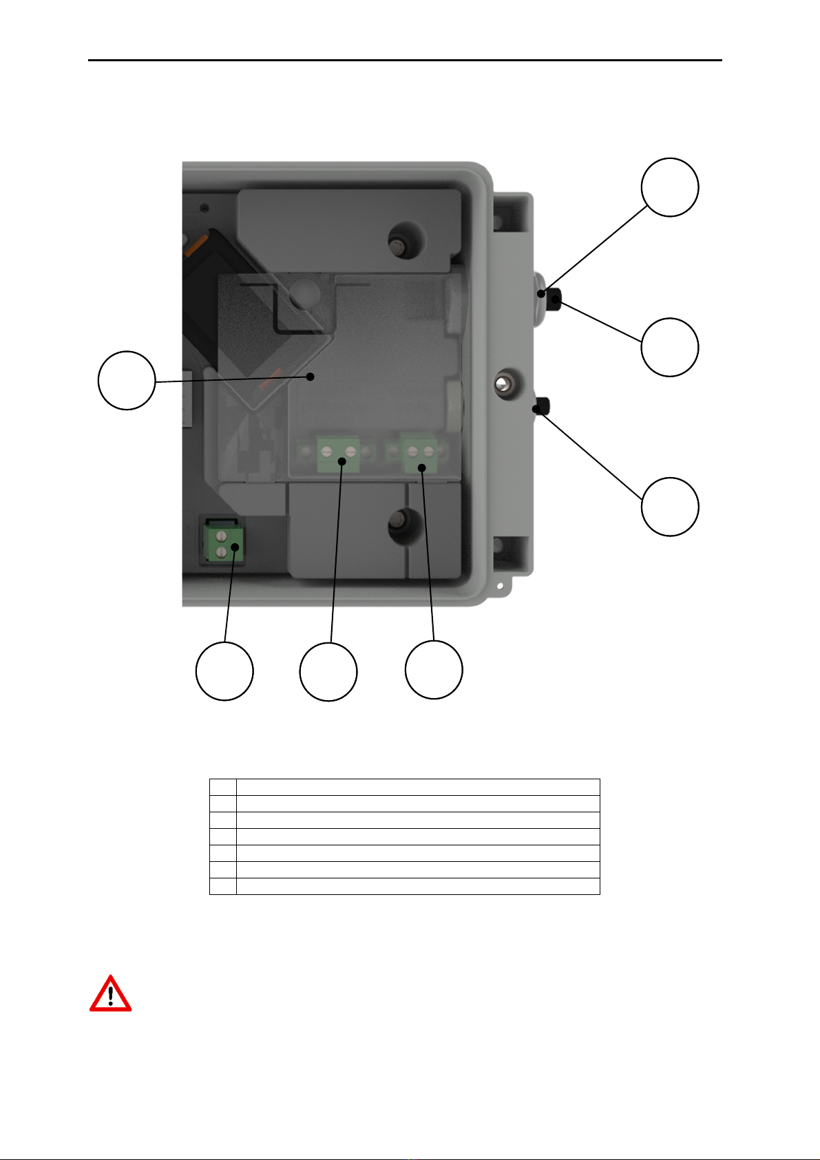
4.8 Power supply connections
Figure 6
Cable glands which are not used must be closed with the enclosed sealing caps.
1
Cable gland for mains voltage
2
Sealing cap for cable gland
3
Cable gland for back
-
up battery
4
24 VDC connection
(15 VDC
-
32 VDC)
5
230 VAC Mains connection
6
Power supply for UNIGAS 300
7
Ex
-
protection cover for mains or external DC voltage
4
6 5
3
1
2
7

Installation and user manual UNICOM 300 N531
DDN5006GHEN/04-2021/rev.B1
13
4.9 Connecting to the mains voltage
Make sure that the mains connection is not live.
First connect UNICOM 300 completely before connecting it to the mains.
Order of connection:
1. Insert a SIM card (if not already done). See also chapter 5 SIM card.
2. Insert the power cable through the appropriate cable gland (Fig. 6, 1).
3. Connect the power cable to the 230 VAC or 24 VDC terminal in the UNICOM 300 (fig. 6, 5).
4. Screw the terminal and the cable gland tight and fit the Ex-protection cap (fig. 6, 7).
5. Connect the power supply for UNIGAS 300 (Fig. 6, 6) (optional).
6. Connect UNICOM 300 to the 230 VAC or 24 VDC mains supply. UNICOM 300 switches on when
the power supply is connected.
7. Adjust the configuration with UNITOOL (optional).
8. Connect the back-up battery (optional).
9. Press SW1 for 5 seconds to log on the modem.
If the device is pre-programmed, it may have already been registered.
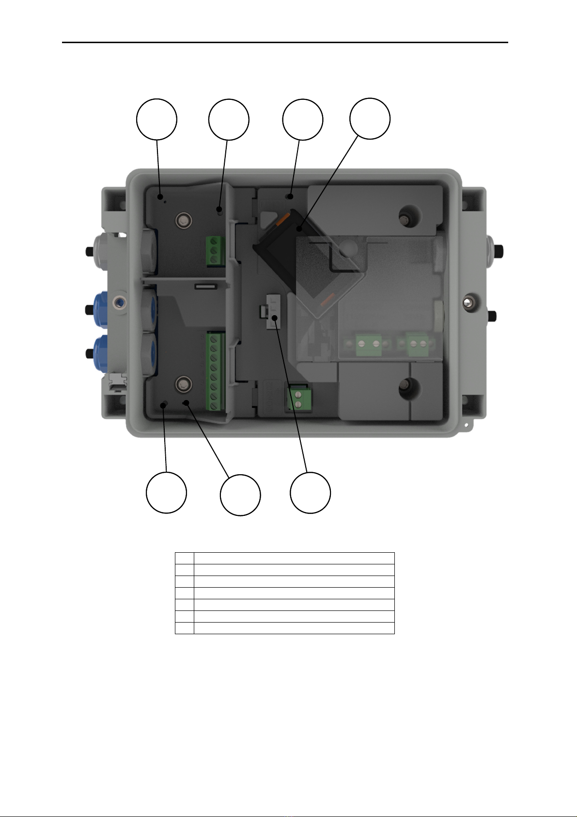
4.10 Connections of the inputs and outputs
Figure 7
1
Puls
outputs,
see table 1
2
Input connections, see table 2
3
Cable g
land for pulse inputs, power supply and encoder
4
Sealing cap for cable gland
5
Cable gland for serial cable UNIGAS 300
6
Cable gland for pulse outputs
1
3
6
2
5
4
Installation and user manual UNICOM 300 N531
DDN5006GHEN/04-2021/rev.B1
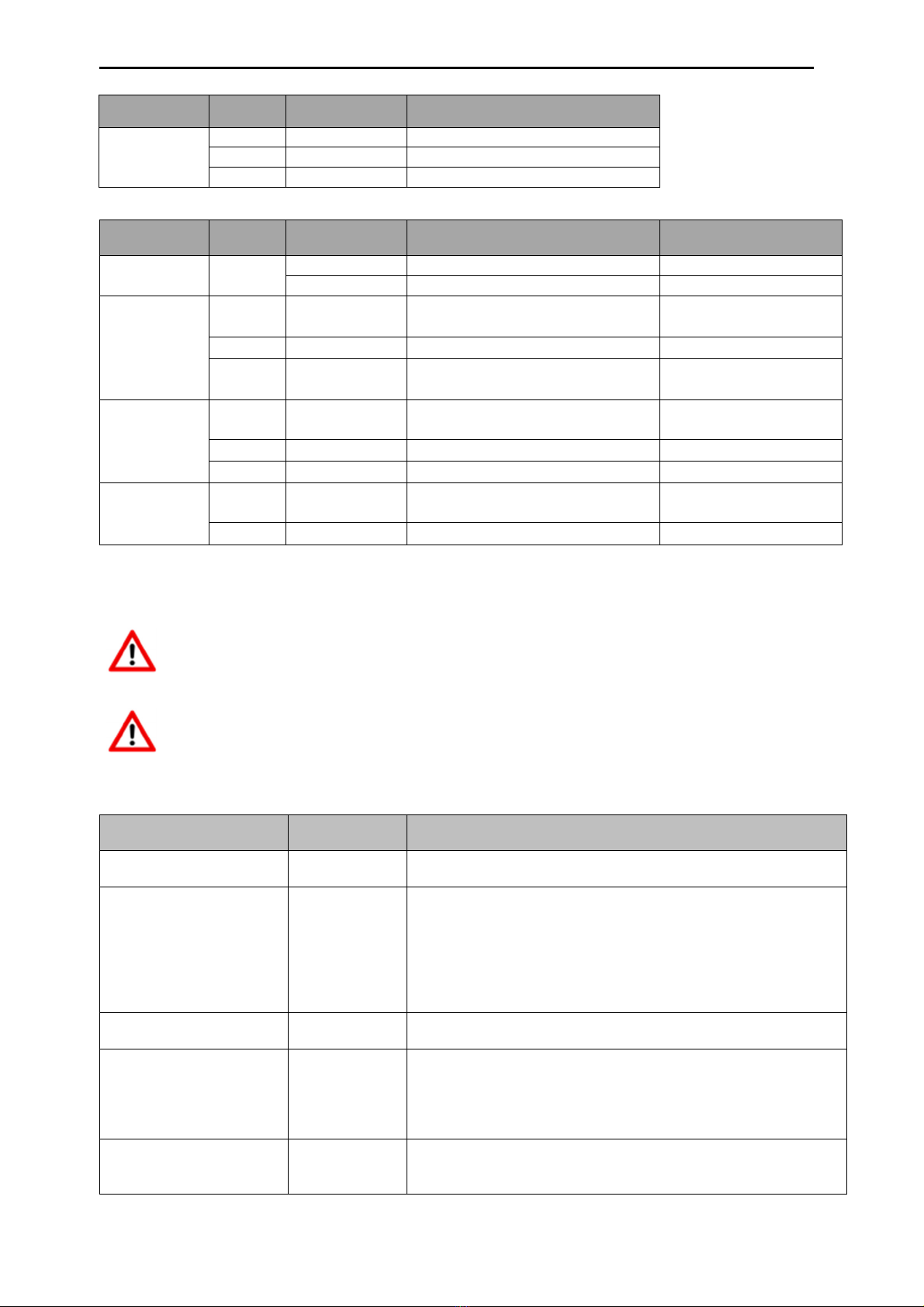
14
Output Terminal
number
Name Function
Pulse 11 Pulse out 2 connection for pulse output 2
10 GND Ground for pulse out cable
9 Pulse out 1 connection for pulse output 1
Table 1: Connections outputs
Input Terminal
number
Name Function Wigersma & Sikkema
cable color coding
Power supply
UNIGAS 300
CON202 + + power supply for UNIGAS 300 Yellow
- - power supply for UNIGAS 300 Grey
Serial 8 REQ Serial data to
UNIGAS EVCD
White
7 GND/SHIELD Ground/shield data cable Black / Green
6 DATA Serial data from
UNIGAS EVCD
Brown
Pulse 5 GND/SHIELD Combined cable ground and
shield for pulse cable
Green
4 PULSE 2 connection for pulse input 2 White
3 PULSE 1 connection for pulse input 1 Brown
Encoder 2 NAMUR - /
GND
Connection for Encoder -
1 NAMUR + Connection for Encoder -
Table 2: connections inputs
See Appendix 3 for connection diagrams for UNICOM 300 - UNIGAS 300.
In order to make a good connection between the threaded ends and the connection terminals
(see Figure 7, 1 and 7, 2), it is important to ensure that the connection terminals are first fully
unscrewed. Then insert the threaded end and tighten the terminals. Check that the threaded end
is properly connected.
A different color coding for the serial wire connection may apply for UNIGAS (see Appendix 5).
4.11 Function switches mains operated UNICOM 300
Switch Switch
operation
Function
optical head detection - Optical head placed;
Status LEDs and optical head detection are activated.
SW1
(MODEM function)
For at least 4
seconds
Modem is turned on; 30 minutes service window is opened. If
modem is on, it is switched off and on again. Status LED’s
are activated during the service window.
To start the device INIT function, switch SW1 must remain
pressed until the INIT LED blinks once every 4 seconds. After
that, SW1 can be released and the initialization will be carried
out further. See also 5.2.
SW1
(MODEM
function
)
For 1 second NOTE! Functionality available from firmware version 11.0.21.
Optical head and status LEDs are activated for 30 minutes.
SW3
(MODEM function)
For at least 4
seconds
Resetting the battery consumption counter of the backup
battery. Reset the power supply type. When changing the
power supply configuration, SW3 must be pressed for at least
4 seconds for a new initialization
Status LED INIT will be on for 10 seconds.
SW1 & SW3
(MODEM function)
For at least 4
seconds
Stock lock activation
After activating stock lock, the status LED will start for 10
seconds. This is independent of state SW
1
/
SW2.
Table 3: function switches (Modem)

Installation and user manual UNICOM 300 N531
DDN5006GHEN/04-2021/rev.B1
15
5 Into service
5.1 SIM-card
UNICOM 300 can be pre-equipped with a SIM-card.
Suitable GSM-subscriptions are for example M2M subscriptions for GSM CSD and/or
GPRS / LTE cat. 1 data.
When using GPRS / LTE Cat. 1, UNICOM 300 requires several settings with which UNICOM 300 can
log on to an APN; such as APN name with the corresponding username and password.
5.2 SIM-card placement
Open UNICOM 300 (see figure 3, note 2). The mini-SIM holder is located in the lid of the UNICOM 300
(see figure 5).
Press lightly on the metal-colored closure of the mini-SIM holder and turn anticlockwise, the mini-SIM
holder unlocks and falls open. The mini-SIM must be inserted with the gold contacts facing backwards
and the angled corner upwards (fig. 8, pos. 1). Close the mini-SIM holder by carrying out the above
operations in reverse order.
Insert the SIM card as shown in figure 8, pos. 2.
After placing the mini-SIM, test the correct operation as described in chapter 5.
When changing SIM cards on the same APN, UNICOM 300 retains its IP address and does not
log in again. However, the device can be reached via GSM CSD on the new number. During a
SIM card change, SW1 must always be pressed for at least 4 seconds to perform a re-
initialization, see also table 3.
Figure 8

Installation and user manual UNICOM 300 N531
DDN5006GHEN/04-2021/rev.B1
16
5.3 Activation and registry
When using the UNICOM 300 as data logger, it is necessary to carry out the following action with the
central acquisition system:
The modem is activated when it is supplied with power (230 VAC / 24 VDC).
The modem can also be activated by pressing SW1 for 4 seconds until the NETWORK status LED
lights up (see figure 3). The UNICOM 300 will now log on. Registration can take several minutes. If
UNICOM 300 is successfully logged on to the network, the network status LED (Table 4) will flash. If
TCP is active, the WDS status LED will be active.
Let the central acquisition system connect to UNICOM 300 and synchronize the clock. This ensures that
the internal clock is synchronized with the central acquisition system. Wigersma & Sikkema delivers
UNICOM 300 standard with deactivated data logger and modem functions. Clock synchronization will
activate the datalogger functions (the scheduler, interval logger, the historical logger and, if activated,
the FTP). If UNICOM 300 is configured for encoder readout, an encoder initialization will also take place
with the data from the gas meter being read out.
5.4 Device init function
The device init function is used for synchronizing the clock with an NTP server, sending a first FTP
message and deactivating the stock lock function after installation of the UNICOM 300.
To activate the device init function, press switch SW1 until status LED INIT flashes once every 4
seconds. Then release SW1.
The device init function can only be activated if NTP, FTP and the APN are programmed.
If they are not programmed, the function cannot be activated, and the status LED INIT will flash 1x per
second when pressing switch SW1.
The initialization then starts, and the current date, time and modem information are requested.
The stock lock of UNICOM 300 is also deactivated. The meter (UNIGAS 300 or UNICOM 300) will then
handle the further device init. If the UNICOM 300 is set as Encoder, the encoder initialization will also be
carried out. When the encoder initialization is complete, the status LED INIT will flash once every 2
seconds.
Next, an FTP message will be sent, and after sending the first FTP message, the status LED INIT will
be on continuously for 10 seconds to indicate that the device init has been completed correctly.
If the device init is not to be executed, the user must release SW1 within 4 seconds.
5.5 Adaptation of use: data logger <-> transparent modem
Adaptation of use as a data logger to use as a transparent modem:
•Check with UNITOOL whether value C.93.15 is "off" or set the value C.93.15 to "off".
•Activate the stock lock function, see table 3.
Adaptation of use as a transparent modem to data logger:
•Check with UNITOOL whether value C.93.15 is set to "on" or set the value C.93.15 to "on".
•This is done automatically with a clock synchronization by the central acquisition system or when
a device init is executed (see chapter 5.4).
5.6 Out of service
If it is necessary to deactivate the UNICOM 300 (take it out of service), it must be ensured that the
modem is not active!
This can be checked by activating SW1 for 1 second (see table 3, from firmware version 11.0.21)
or activating the communication port SW2 which causes the status LED to display.
LED "Network" must be off, see also Table 4.

Installation and user manual UNICOM 300 N531
DDN5006GHEN/04-2021/rev.B1
17
6 Activation of the modem, TCP and NTP services
6.1 Activation of the modem
The modem can be turned on by pressing switch SW1 for at least 4 seconds until the NETWORK status
LED starts flashing, SW1 can then be released.
If switch SW1 is operated again, the modem will log in again, turning the modem off and on again. This
is apparent as the NETWORK status LED (see Chapter 5) is off for a short time.
6.2 Activation of TCP services
If the TCP server function is activated in UNICOM 300, the device will log on to GPRS/LTE cat. 1 when
the modem is switched on.
Before the TCP server is activated an IP-address will be assigned to UNICOM 300. If logging on to
GPRS/LTE cat. 1, or activating the TCP server fails, this will be repeated up to four times. If after four
attempts the registration is not successful, UNICOM 300 will be registered on the GSM network,
(NETWORK status LED will flash) but not on the GPRS/LTE cat. 1 network. The user may optionally
initiate a re-login by means of switch SW1.
6.3 Activation of NTP
UNICOM 300 is equipped with a function to read out the NTP-time server. When connected to this time
server, the date and time are read out. If NTP is activated and UNICOM 300 has been synchronized with
the NTP server in the last 24 hours, then UNICOM MODEM's clock is no longer synchronized by
monitoring data traffic.
To activate NTP functionality, the NTP time server must be set via C92.65 and C.92.66. In addition, the
APN data must also be set.
The requested NTP time is the GMT time. Through time zone setting (C.92.64) and with DST
(summer/winter time) the time is adjusted in UNICOM 300.
When the NTP function is activated, the clock is requested once a day at approximately 00:35.
If reading out the NTP time server does not succeed, another attempt will be made after 12 hours.
6.4 Activation of FTP
To use the FTP functionality, the FTP server data must be set (FTP server, FTP user name, FTP
password, FTP port). Also the APN data and the FTP interval have to be set.
If the FTP functionality of the UNICOM 300 is activated, the UNICOM 300 will send the load profile after
activating the datalogger. See chapter 8 for activation of the data log functions. If UNICOM 300 is placed
as modem at UNIGAS 300 and CI module, UNICOM 300 will forward the FTP message from UNIGAS
300.
UNICOM 300 checks if the FTP message arrived correctly on the server. At first installation or at not
correctly sending the FTP message, UNICOM 300 or UNIGAS 300 will, when sending the (next) FTP
message, send the data of the failed message. The data is depending on the set load profile (0.8.5) limited
as follows:
Setting 0.8.5:
5 minutes = 10 days
10 minutes = 10 days
15 minutes = 31 days
30 minutes = 31 days
60 minutes = 61 days
1 day = 61 days

Installation and user manual UNICOM 300 N531
DDN5006GHEN/04-2021/rev.B1
18
7 Function Check
7.1 Checking the system status by means of the status LEDs
There are eight status LEDs on mains operated UNICOM 300 that show different states. The status
LEDs are active if an optical head is placed on the communication port (SW2, figure 3), or if SW1 (figure
3) is operated. This way, the status LEDs are only active in the event that a technician is on site.
Status LED Condition LED (see figure 6)
PWR;
Supply
Continuously on; Power supply voltage good
Blinking 1 x per 4 seconds; Power supply voltage low
Blinking 1 x per second; Backup battery empty
STATUS;
UNICOM status
10 seconds on; Stock lock activated
Blinking 1 x per 4 seconds; Stock lock activated
Blinking 1 x per 2 seconds; Stock lock not activated
Blinking
1 x per
second
;
Critical error
Network;
Network status
Continuously on; network registry started
Blinking 1 x per 4 seconds; registered on network
Blinking 1 x per 2 seconds; Connection (CSD; FTP; TCP)
Off; Modem off
WDS;
2G/4G status
Continuously on; Registered on 2G / TCP services
Blinking 1 x per 4 seconds; Registered on 4G
Blinking 1 x per 2 seconds; Registered on 4G / TCP services
Off; registered on 2G CSD
SIG1;
GSM signal status
Continuously on; Main cell < -92 dBm
Blinking 1 x per 4 seconds; Main cell ≥-92 dBm en < -80 dBm
Blinking 1 x per 2 seconds; Main cell ≥-80 dBm
SIG2; Not functional
INIT;
10 seconds continuously on; device INIT successfully
completed or battery counters reset
Blinking 1 x per 4 seconds; device INIT started
Blinking 1 x per 2 seconds; Encoder readout completed
Blinking 1 x per second; device INIT in ERROR
Off: device INIT not activated
DATA; Blinking at transfer of data by modem
Table 4: status LEDs UNICOM 300
7.2 Checking the system status data logger
On the logger part of UNICOM 300 two status LEDs (see figure 4) are available which show different
conditions.
Status
LED
Condition
LED
(
see
figur
e
6)
Status Blinking 5 ms every 10 seconds; Stock lock activated
Blinking
5 ms
every
5 second
;
Stock lock
not activated
Encoder 10 seconds on; Encoder initialization completed successfully
Blinking 1x per 2 seconds; Encoder initialization active
Blinking
1x per
second
;
repeated every 10 seconds
. Encoder
initialization
in error.
Power supply
PCA
LED on; power supply present
LED
off
;
no power supply
present
Table 5: status LEDs UNICOM 300 datalogger

Installation and user manual UNICOM 300 N531
DDN5006GHEN/04-2021/rev.B1
19
8 Configuration
8.1 Gas meters with encoder
Application: data logger
UNICOM 300 is suitable for the use of gas meters with an encoder output from the Itron, GWF,
Honeywell (Elster), Dresser, FMG, RMG, GFO or RMA (Aerzen) products, which are equipped with a
NAMUR interface. To use this function, parameter C.93.40 must be set on by means of UNITOOL
service software. Registration of the encoder counting mode takes place in counter 3.
8.1.1 Initialization
encoder
Because UNICOM 300 is provided with a check on the encoder counter value, not every counter value
will be accepted (see chapter 8.1.4). To ensure that UNICOM 300 takes over the encoder counter value
once, when UNICOM 300 is installed or when changing the gas meter, UNICOM 300 has four ways to
initialize the encoder counter:
1. If the data logger functions are activated. The interval logger and the historic logger are
deleted. Activation can be performed using:
-UNITOOL and setting parameter C.93.30; deactivating stock lock
or
-Takes place when the clock of UNICOM 300 is synchronized by for example a central
data acquisition system or manual time synchronization.
2. When parameter C.93.40 is set to value “encoder” by means of service software UNITOOL
3. Manual initialization by SW4 (see chapter 8.1.2)
4. Device init as described in chapter 5.2.
8.1.2 Manual encoder initialization
It is possible for a user to manually start an encoder initialization on location.
The procedure is as follows:
-Press SW4 until the Encoder status LED blinks 1x per 2 seconds or is continuously on.
-The Encoder status LED will show the status of the initialization (see table 5).
8.1.3 Readout of gas meter data
UNICOM 300 will, if supported by the encoder counter, read the gas meter data. Data from the gas
meter are serial number, manufacturer and year of manufacturing.
The data from the gas meter is read out:
- When encoder initialization takes place, see chapter 8.1.1.
- If the encoder counter is read out successfully after a failure notification of encoder readout
has been set in the status registry.
8.1.4 Readout of encoder counters
If an encoder counter is connected without initializing it and the position of the encoder counter is lower
or much higher than the value in counter 3 (Vm3) of UNICOM 300, UNICOM 300 will not take over the
encoder counter mode. In the status register a message is made of an incorrect readout of the encoder
counter.
If the encoder counter is reduced, the counter mode will not be adopted by UNICOM 300. A status
message is made of this in the status register. If the return is temporary, UNICOM 300 will take over the
counting position again as soon as it is larger than the last meter reading.

Installation and user manual UNICOM 300 N531
DDN5006GHEN/04-2021/rev.B1
20
8.2 Gas meters with a pulse
Application: data logger
Input 1 is always set to pulse, input 2 may be set to pulse or alarm.
Check and / or program the correct pulse ratios (parameter 1:0.7.2 and 2:0.7.2) by means of the
UNITOOL service software.
For UNICOM 300 pulse outputs, a choice can then be made for Vm1-Vm2-Vm3 or Alarm1 via the
parameters mentioned in chapter 11.
8.3 Transparent modem (Electronic volume converter type UNIGAS)
Application: modem for EVC types UNIGAS
Connect the serial cable of the UNIGAS to the serial terminals and make sure settings are as described
in chapter 5.5 and activate the modem.
8.4 Deactivating the data logger
If necessary, the data logger functions of UNICOM 300 can be deactivated.
Deactivation can be performed using UNITOOL and setting parameter C.93.30 or by activating stock lock
with SW1 and SW3 (see table 3).
9 External antennas
Wigersma & Sikkema has external antennas for various applications; a round-beam antenna, a
directional antenna and a vandal-proof antenna. The external antennas are supplied with mounting
material and instructions for connection to UNICOM 300.
The standard antenna can be loosened from the UNICOM 300. Another antenna can then be connected
to the free connection. See also DDN003MHEN
If the external antenna is placed in the Ex zone, the antenna must not have a gain
greater than 2 dB.
10 Software
The following software package is available
•Configuration and readout of a single UNICOM 300:
UNITOOL software: https://www.wigersma-sikkema.com/en/downloads-2/software/
Other manuals for UNICOM 300
2
Table of contents
Other Wigersma & Sikkema Modem manuals

Popular Modem manuals by other brands

SIRETTA
SIRETTA MICA Series Software manual

Gtran Wireless
Gtran Wireless Z010 user manual

NETGEAR
NETGEAR AC327U installation guide

B&B Electronics
B&B Electronics X09-009PKC-EA Product information

ZyXEL Communications
ZyXEL Communications eir F1000 user guide

Sierra Wireless
Sierra Wireless AirCard 595 quick start guide


Motorola
Motorola SURFboard SB5102 Safety and regulatory information

Whirlwind
Whirlwind E BEAM installation guide

FRITZ!WLAN
FRITZ!WLAN AC 860 Configuration and operation manual

Sunrise
Sunrise Internet Box Fiber quick guide

Arris
Arris SURFboard SBG6900-AC quick start guide

Fritz!
Fritz! AC430 MU-MIMO Configuration and operation