Wilbur Curtis Primo Cappuccino PCGT3 User manual

Primo Cappuccino™3 Station
Dispensing System
USER GUIDE
READ AND SAVE THESE INSTRUCTIONS
NOTICE TO INSTALLER: Please leave this booklet with the machine.
øøøøø "
'$1$(5'30/5$07&3 'SFW/$

CONTENTS CL40
.H\)HDWXUHV6SHFLÀFDWLRQV6\VWHP5HTXLUHPHQWV..............................................................................................FS40
,PSRUWDQW6DIHJXDUGV............................................................................................................................................... IS2
,QVWDOODWLRQ,QVWUXFWLRQV*HQHUDO...............................................................................................................................II2
,QVWDOODWLRQ,QVWUXFWLRQV/HYHOLQJ:DWHU6XSSO\(OHFWULFDO....................................................................................II22
2SHUDWLQJ,QVWUXFWLRQV ............................................................................................................................................OI33
&OHDQLQJ,QVWUXFWLRQV*HQHUDO..............................................................................................................................CI19
&OHDQLQJ,QVWUXFWLRQV:KLSSHU3ODWH$VVHPEO\ ...................................................................................................CI20
3URJUDPPLQJ*XLGH ............................................................................................................................................. 3*
5RXJK,Q'UDZLQJ................................................................................................................................................. 5'
,OOXVWUDWHG3DUWV5HFRPPHQGHG3DUWV0DLQ&KDVVLV........................................................................................... ,3
,OOXVWUDWHG3DUWV5HFRPPHQGHG3DUWV7DQN$VVHPEO\6WDQGDUG ....................................................................... ,3
,OOXVWUDWHG3DUWV5HFRPPHQGHG3DUWV7DQN$VVHPEO\'XDO9ROWDJH ................................................................. ,3
,OOXVWUDWHG3DUWV5HFRPPHQGHG3DUWV7DQN$VVHPEO\([SRUW ........................................................................... ,3
(OHFWULFDO6FKHPDWLFV ............................................................................................................................................(6
7URXEOHVKRRWLQJ*XLGH*HQHUDO..........................................................................................................................7*
7URXEOHVKRRWLQJ*XLGH'XPS9DOYH&DOLEUDWLRQ.................................................................................................7*
(UURU&RGHV .............................................................................................................................................................(&
3URGXFW:DUUDQW\....................................................................................................................................................3:
Contact Information
Wilbur Curtis Co., Inc.
6913 Acco Street | Montebello, CA 90640 US
Phone: 323-837-2300 | Toll Free: 800-421-6150
'PSUIFMBUFTUTQFDJmDBUJPOTBOEJOGPSNBUJPOHPUPXXXXJMCVSDVSUJTDPN
5PMM'SFF].POEBZ'SJEBZA.M.- 4:00 P.M.PT
Email: [email protected]
%VFUPDPOUJOVFEQSPEVDUJNQSPWFNFOUUIFQSPEVDUTJMMVTUSBUFEQIPUPHSBQIFEJOUIJTHVJEFNBZWBSZTMJHIUMZGSPNUIFBDUVBMQSPEVDU
1$(5$0/5&/54-*45øø 021618NC

KEY FEATURES/SPECIFICATIONS/SYSTEM REQUIREMENTS FS40
Key Features
• G3 Digital Control Module - Provides precise control over all critical blending and dispensing functions.
• Pre-Dispense - Easy to use. Choose a size from small, medium or large by the touch of a button.
• Factory Pre-Set - For out-of-the-box operation.
• LCD Digital Display - Extra bright and easy to use.
• 4DSPMM5ISPVHI1SFDJTJPO1SPHSBNNJOH"EKVTUQPXEFSnPXJOJODSFNFOUTBOEXBUFSUFNQFSBUVSFGSPN¡'
UP¡'¡$UPDSFBUFUIFQFSGFDUIPUPSDPMECFWFSBHF
6SHFLÀFDWLRQV6HOHFWHG0RGHOV
(OHFWULFDO6XSSO\5HTXLUHPHQWV
02'(/ '(6&5,37,21 3+$6( 92/76 $036 +($7,1*&21),* :,5( :$776 +(57= &$3$&,7<
3&*7 3 Station 1 PH 120 V 15.0 A 1 x 1600 W 2W + G 1800 W 50/60 Hz 5.4 gal/hr
[20.4 l/hr]
3&*7'9 3 Station, dual voltage 1 PH 120/220 V 15.0/14.5 A 2 x 1600 W 2W/3W + G 1800/3000 W 50/60 Hz 5.4/10.7 gal/hr
[20.4/40.5 l/hr]
3&*7 3 Station with lift door 1 PH 120 V 15.0 A 1 x 1600 W 2W + G 1800 W 50/60 Hz 5.4 gal/hr
[20.4 l/hr]
3&*7 3 Station, pre-set dispense 1 PH 120 V 15.0 A 1 x 1600 W 2W + G 1800 W 50/60 Hz 5.4 gal/hr
[20.4 l/hr]
3&*7 3 Station with hot water faucet 1 PH 120 V 15.0 A 1 x 1600 W 2W + G 1800 W 50/60 Hz 5.4 gal/hr
[20.4 l/hr]
3&*7 3 Station, iced coffee 1 PH 120 V 15.0 A 1 x 1600 W 2W + G 1800 W 50/60 Hz 5.4 gal/hr
[20.4 l/hr]
(;3257
3&*7( 3 Station, export 1 PH 230 V 11.5 A 1 x 2000 W 2W + G 2650 W 50/60 Hz 10.9 gal/hr
[41.3 l/hr]
'LPHQVLRQV :DWHU6XSSO\5HTXLUHPHQWV
02'(/ +(,*+7 :,'7+ '(37+ 6+,3:(,*+7 6+,3&8%( :$7(5&211(&725 :$7(535(6685( 0,1)/2:5$7(
3&*7
34.78”
[88.3 cm]
14.25”
[36.2 cm]
24.54”
[62.3 cm]
125.0 lbs
[56.7 kg]
21.64 cu. ft.
[0.16 m3]µÁDUH
20 - 90 psi
[138 - 620 kPa]
1.0 gpm
[3.8 lpm]
3&*7'9
3&*7
3&*7
3&*7
3&*7
(;3257
3&*7( 34.78”
[88.3 cm]
14.25”
[36.2 cm]
24.54”
[62.3 cm]
125.0 lbs
[56.7 kg]
21.64 cu. ft.
[0.16 m3]µÁDUH
20 - 90 psi
[138 - 620 kPa]
1.0 gpm
[3.8 lpm]
PCGT3, KEY FEATURES/SPECS/SYSTEM REQUIREMENTS "
Following are the factory default settings for the Primo Cappuccino dispenser:
• 1PXEFS3BUJP• Water Temperature = ¡'¡$TUBOEBSEVOJUT
¡'¡$JDFEDBQQVDDJOPVOJUT

IMPORTANT SAFEGUARDS IS2
Symbols
This is the safety alert symbol. It is used to alert you to potential physical injury hazards. Obey all safety
messages that follow this symbol to avoid possible injury or death.
DANGER - Indicates a hazardous situation which, if not avoided, will result in death or serious injury.
WARNING - Indicates a hazardous situation which, if not avoided, could result in death or serious injury.
CAUTION - Indicates a hazardous situation which, if not avoided, could result in minor or moderate injury.
NOTICE - Indicates a situation which, if not avoided, could result in property damage.
IMPORTANT - Provides information and tips for proper operation.
SANITATION REQUIREMENTS
Important Safeguards/Conventions
WARNING:
• Make sure that this appliance is installed and grounded according to the INSTALLATION
*/4536$5*0/4CZRVBMJmFEQFSTPOOFMCFGPSFBUUFNQUJOHUPVTFJU'BJMVSFUPGPMMPXUIF*/45"--"5*0/
INSTRUCTIONS could result in personal injury or void the warranty.
• This appliance is designed for commercial use. Any service other than cleaning and preventive
maintenance should be performed by an authorized Wilbur Curtis service technician.
• 5PSFEVDFUIFSJTLPGmSFPSFMFDUSJDTIPDL%0/05PQFOUIFTFSWJDFQBOFMT5IFSFBSFOPVTFS
serviceable parts inside.
• Keep hands, arms and other items away from hot surfaces of the unit during operation.
• Clean the appliance and any dispensers completelyCFGPSFVTJOHUIFNGPSUIFmSTUUJNFBDDPSEJOHUP
the CLEANING INSTRUCTIONS. Clean them regularly as instructed in the CLEANING INSTRUCTIONS.
• Use this appliance only for its intended use, brewing/dispensing hot and/or cold beverages/water.
• This appliance is not intended for use by persons (including children) with reduced physical, sensory
or mental capabilities or lack of experience and knowledge, unless they have been given supervision
or instruction concerning use of the appliance by a person responsible for their safety. Children should
be supervised to ensure that they do not play with the appliance.
• Avoid spillage onto the power (mains) connector.
$0''&&5&"#3&8&34*.1035"/54"'&(6"3%44:.#0-4 (
WARNING - 5IJTQSPEVDUDBOFYQPTFZPVUPDIFNJDBMTJODMVEJOH"DSZMBNJEFBOE#JTQIFOPM"#1"
which are known to the State of California to cause cancer and birth defects or other reproductive harm.
'PSNPSFJOGPSNBUJPOWJTJUXXX18BSOJOHTDBHPW

IMPORTANT SAFEGUARDS IS2
$0''&&5&"#3&8&34*.1035"/54"'&(6"3%44:.#0-4 (
CE Requirements
• This appliance must be installed in locations where it can be overseen by trained personnel.
• 'PSQSPQFSPQFSBUJPOUIJTBQQMJBODFNVTUCFJOTUBMMFEXIFSFUIFUFNQFSBUVSFJTCFUXFFO¡$UP¡$
• "QQMJBODFTIBMMOPUCFUJMUFENPSFUIBO¡GPSTBGFPQFSBUJPO
• "OFMFDUSJDJBONVTUQSPWJEFFMFDUSJDBMTFSWJDFBTTQFDJmFEJODPOGPSNBODFXJUIBMMMPDBMBOEOBUJPOBMDPEFT
'PSTBGFVTFBOBMMQPMFEJTDPOOFDUJPONVTUCFJODPSQPSBUFEJOUPUIFmYFEXJSJOHJOBDDPSEBODFXJUIUIF
XJSJOHSVMFTPVUMJOFEJODMBVTFPG*&$GPSNFFUJOHUIFNJOJNVNFMFDUSJDBMTBGFUZPGUIJTTUBOEBSE
• This appliance must not be cleaned by water jet.
• 5IJTBQQMJBODFDBOCFVTFECZQFSTPOTBHFEGSPNZFBSTBOEBCPWFJGUIFZIBWFCFFOHJWFOTVQFSWJTJPOPS
instruction concerning use of the appliance in a safe way and if they understand the hazards involved.
• ,FFQUIFBQQMJBODFBOEJUTDPSEPVUPGSFBDIPGDIJMESFOBHFEMFTTUIBOZFBST
• "QQMJBODFTDBOCFVTFECZQFSTPOTZFBSTBOEBCPWFXJUISFEVDFEQIZTJDBMTFOTPSZPSNFOUBMDBQBCJMJUJFT
or lack of experience and knowledge if they have been given supervision or instruction concerning use of the
appliance in a safe way and understand the hazards involved.
• $IJMESFOVOEFSUIFBHFPGZFBSTTIPVMECFTVQFSWJTFEUPFOTVSFUIFZEPOPUQMBZXJUIUIFBQQMJBODF
• If the power cord is ever damaged, it must be replaced by the manufacturer or authorized service personnel
with a special cord available from the manufacturer or its authorized service personnel in order to avoid a
hazard.
• Machine must not be immersed for cleaning.
• $MFBOJOHBOEVTFSNBJOUFOBODFTIBMMOPUCFNBEFCZDIJMESFOVOMFTTUIFZBSFPMEFSUIBOZFBSTBOE
supervised.
• This appliance is intended to be used in household and similar applications such as:
oTUBGGLJUDIFOBSFBTJOTIPQTPGmDFTBOEPUIFSXPSLJOHFOWJSPONFOUT
oCZDMJFOUTJOIPUFMTNPUFMTBOEPUIFSSFTJEFOUJBMUZQFFOWJSPONFOUT
– bed and breakfast type environments.
• This appliance not intended to be used in applications such as:
– farm houses
• Access to the service areas permitted by Authorized Service personnel only.
• 5IF"8FJHIUFETPVOEQSFTTVSFMFWFMJTCFMPXE#"

INSTALLATION INSTRUCTIONS II2
Installation Instructions
Installation Requirements
• A secure surface capable of supporting the weight of the appliance.
• For units without an attached cord set: Appropriately sized, UL listed, grounding type power cable to meet
UIFFMFDUSJDBMTQFDJmDBUJPOTGPSUIFBQQMJBODF*GZPVIBWFRVFTUJPOTBCPVUUIFDPSSFDUDBCMFTJ[FBOEMFOHUI
DPOTVMUBRVBMJmFEJOTUBMMFS*GUIFBQQMJBODFXJMMCFIBSEXJSFEUPBKVODUJPOCPYUIFQPXFSDBCMFNVTUCFMPOH
enoughTPUIBUUIFVOJUDBOCFNPWFEGPSDMFBOJOHVOEFSOFBUI
• "HSPVOEFEFMFDUSJDBMDPOOFDUJPOUPBOFMFDUSJDBMDJSDVJUUIBUNFFUTUIFFMFDUSJDBMTQFDJmDBUJPOTPGUIF
appliance (see SPECIFICATIONS5IFDJSDVJUNVTUCFQSPUFDUFECZUIFBQQSPQSJBUFTJ[FEDJSDVJUCSFBLFS*G
ZPVBSFOPUDFSUBJOUIBUUIFFYJTUJOHDJSDVJUNFFUTUIFSFRVJSFNFOUTGPSZPVSVOJUDPOTVMUBMJDFOTFEFMFDUSJDJBO
• "XBUFSmMUSBUJPOTZTUFNJTSFRVJSFEUPNBJOUBJOUSPVCMFGSFFPQFSBUJPO8JMCVS$VSUJT$P*ODSFDPNNFOETB
8JMCVS$VSUJTBQQSPWFEXBUFSmMUFS4FFUIF$VSUJT&RVJQNFOU$BUBMPHGPSBGVMMMJOFPG8JMCVS$VSUJTBQQSPWFE
XBUFSmMUFST
• 1PUBCMFXBUFSTVQQMZMJOFDPOOFDUJPOGSPNUIFXBUFSmMUFSDBQBCMFPGTVQQMZJOHUIFNJOJNVNnPXSBUFSFRVJSFE
CZUIFTQFDJmDBUJPOT5IFXBUFSTVQQMZMJOFNVTUCFBCMFUPDPOOFDUUPUIFnBSFmUUJOHPOUIFCBDLPGUIF
VOJU4FFUIFSPECIFICATIONS section for the correct size. The water line should also be capable of being
DPOUSPMMFECZBTIVUPGGWBMWF%POPUDPOOFDUUIFXBUFSMJOFUPBTBEEMFWBMWFPSOFFEMFWBMWF
/4'*OUFSOBUJPOBMSFRVJSFTUIFGPMMPXJOHXBUFSDPOOFDUJPO
1 "RVJDLEJTDPOOFDUPSBEEJUJPOBMDPJMFEUVCJOHBUMFBTUUXPUJNFTUIFEFQUIPGUIFapplianceJTSFRVJSFE
TPUIBUJUDBOCFNPWFEGPSDMFBOJOHVOEFSOFBUI
2 5IJTFRVJQNFOUJTUPCFJOTUBMMFEXJUIBEFRVBUFCBDLnPXQSPUFDUJPOUPDPNQMZXJUIBQQMJDBCMF
federal, state and local codes.
8BUFSQJQFDPOOFDUJPOTBOEmYUVSFTEJSFDUMZDPOOFDUFEUPBQPUBCMFXBUFSTVQQMZTIBMMCFTJ[FE
installed and maintained in accordance with federal, state and local codes.
WARNING:*OTUBMMBUJPOJTUPCFQFSGPSNFEPOMZCZBRVBMJmFEJOTUBMMFS
WARNING: *NQSPQFS FMFDUSJDBM DPOOFDUJPO NBZ SFTVMU JO BO FMFDUSJD TIPDL IB[BSE 5IJT CSFXFS NVTU CF
properly grounded.
NOTICE:%0/05DPOOFDUUIJTCSFXFSUPBIPUXBUFSTVQQMZ5IFXBUFSJOMFUWBMWFJTOPUSBUFEGPSIPUXBUFS
%POPUFYDFFEUIFNBYJNVNXBUFSQSFTTVSFTUBUFEJOUIFSPECIFICATIONS section.
IMPORTANT:0CTFSWFBMMHPWFSOJOHDPEFTBOEPSEJOBODFT
#3&8&34(&/&3*$*/45"--"5*0/*/4536$5*0/4 %
5IF*OUFSOBUJPOBM1MVNCJOH$PEFPGUIF*OUFSOBUJPOBM$PEF$PVODJMBOEUIF'PPEBOE%SVH"ENJOJTUSBUJPO
'%"'PPE$PEFNBOVBMEJSFDUUIBUUIJTFRVJQNFOUNVTUCFJOTUBMMFEXJUIBEFRVBUFCBDLnPXQSFWFOUJPO
JODPNQMJBODFXJUIGFEFSBMTUBUFBOEMPDBMDPEFT'PSVOJUTJOTUBMMFEPVUTJEFPGUIF64"NBLFTVSFUIBU
the installation is in compliance with the applicable plumbing/sanitation code for your area.
INSTALLATION INSTRUCTIONS II22
Style may vary
Style may vary
Strain
relief
220 Volt
power
cable
Terminal
block
Installation
Leveling
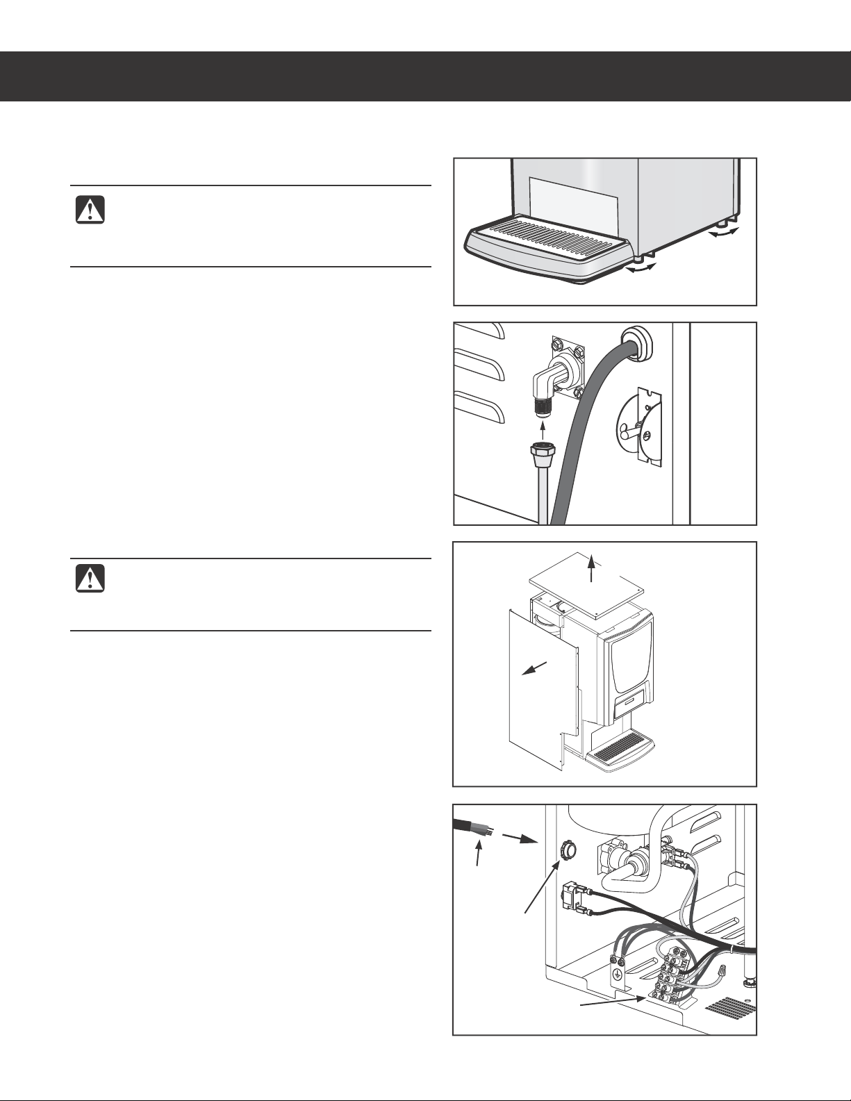
1 Position the dispenser on the counter top. Level it left
to right and front to back by turning the bottom of the
legs.
Connect the Water Supply
2 Flush the water supply line prior to installation to
QVSHFBJSBOEEFCSJTGSPNUIFXBUFSmMUFSBOEUVCJOH
3 $POOFDUUIFXBUFSTVQQMZMJOFUPUIFnBSFmUUJOHPOUIF
back of the unit. Leave the water supply valve closed
until power is connected.
Connect the Wiring - Dual Voltage Units to be Operated
220-240 Volts Only
4 Remove the top cover and the left side panel to
expose the terminal block.
5 Disconnect and cap the jumper wire between the “C”
and “N” terminals on the terminal block.
6 Loosen the strain relief on the back panel.
7 Disconnect the 120 Volt power cable from the terminal
block and pull the cable out through the back.
8 Feed the end of the 220-240 Volt power cable through
the strain relief, into the unit.
9 Connect the wires on the power cable to the terminal
block inside.
10 Tighten the strain relief and replace the side and top
panels.
11 Connect the power cable wires to the terminals in the
junction box. See the ELECTRICAL SCHEMATIC for
the power supply requirements.
WARNING: Use the leveling legs to level the
dispenser only. Do not use them to adjust
dispenser height. Do not extend them higher
than necessary.
WARNING: Turn off power to the junction box at
the circuit breaker panel before connecting the
power cable to the dispenser. Lock out and tag
the circuit breaker.
1$(5&913*/45"--"5*0/*/4536$5*0/4ø 100318A
Back of unit
d
c
INSTALLATION INSTRUCTIONS II22
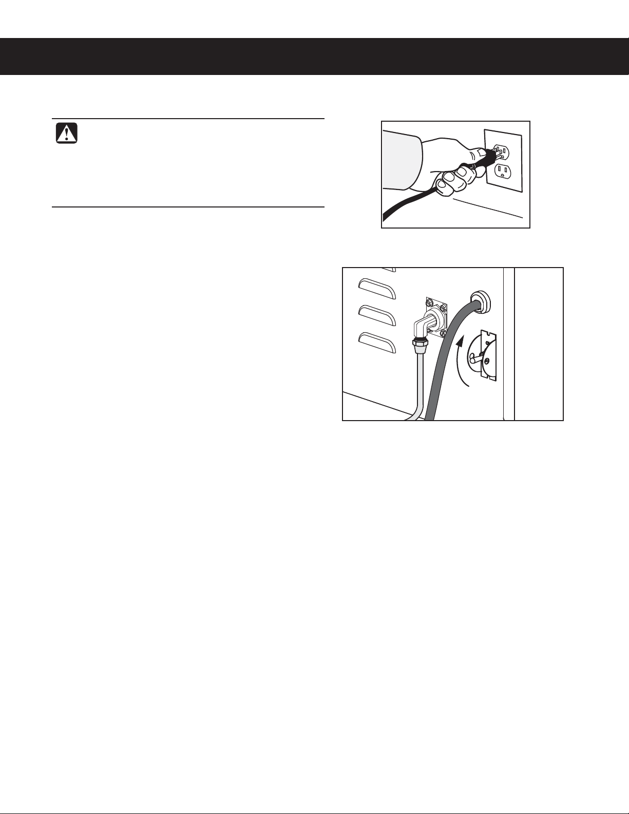
Connect the Power Cable - 120 Volt Units
12 Connect the power cord to the appropriate type of
electrical outlet.
Power Up the Unit
13 Turn on the water supply valve.
14 Make sure that the circuit breaker supplying power to
the dispenser is on.
15 Turn the toggle switch on the back of the dispenser to
UIF0/QPTJUJPO5IFXBUFSUBOLXJMMTUBSUUPmMM8IJMF
UIFUBOLJTmMMJOHJOTQFDUUIFXBUFSTVQQMZMJOFGPSMFBLT
16 8IFOUIFXBUFSMFWFMJOUIFUBOLSJTFTUPUIF
correct volume, the heating element(s) will turn on
automatically. Depending on the incoming water
UFNQFSBUVSFBOEUIFFMFDUSJDBMTQFDJmDBUJPOTUIFXBUFS
tank typically requires 1 hour to reach the factory set
PQFSBUJOHUFNQFSBUVSF8IFOUIFXBUFSIBTIFBUFE
“Ready to Dispense” should be on the display.
17 If the unit is equipped with a hot water faucet, before
VTJOHUIFVOJUGPSUIFmSTUUJNFEJTQFOTFPVODFTPG
hot water from the hot water faucet to help purge air
from the tubing inside the unit.
18 Dispense at least 12 ounces from each spout, to purge
any remaining air from the tubing. See OPERATING
INSTRUCTIONS. During initial dispensing, and
XIFOFWFSUIFmMUFSJTSFQMBDFEZPVNBZIFBSUIF
TPVOETPGBJSCFJOHQVSHFEGSPNUIFmMUFSUVCJOHBOE
water tank.
WARNING: Connect the power cord to the
appropriate type and size electrical outlet. If the
electrical outlet is not compatible with the power
cord, have it upgraded by a licensed electrician.
Do not modify the power plug. Do not use an
extension cord. Do not use a power cord/plug that
is damaged.
1$(5&913*/45"--"5*0/*/4536$5*0/4ø 100318A
OPERATING INSTRUCTIONS OI33
1$(501&3"5*/(*/4536$5*0/4øø "
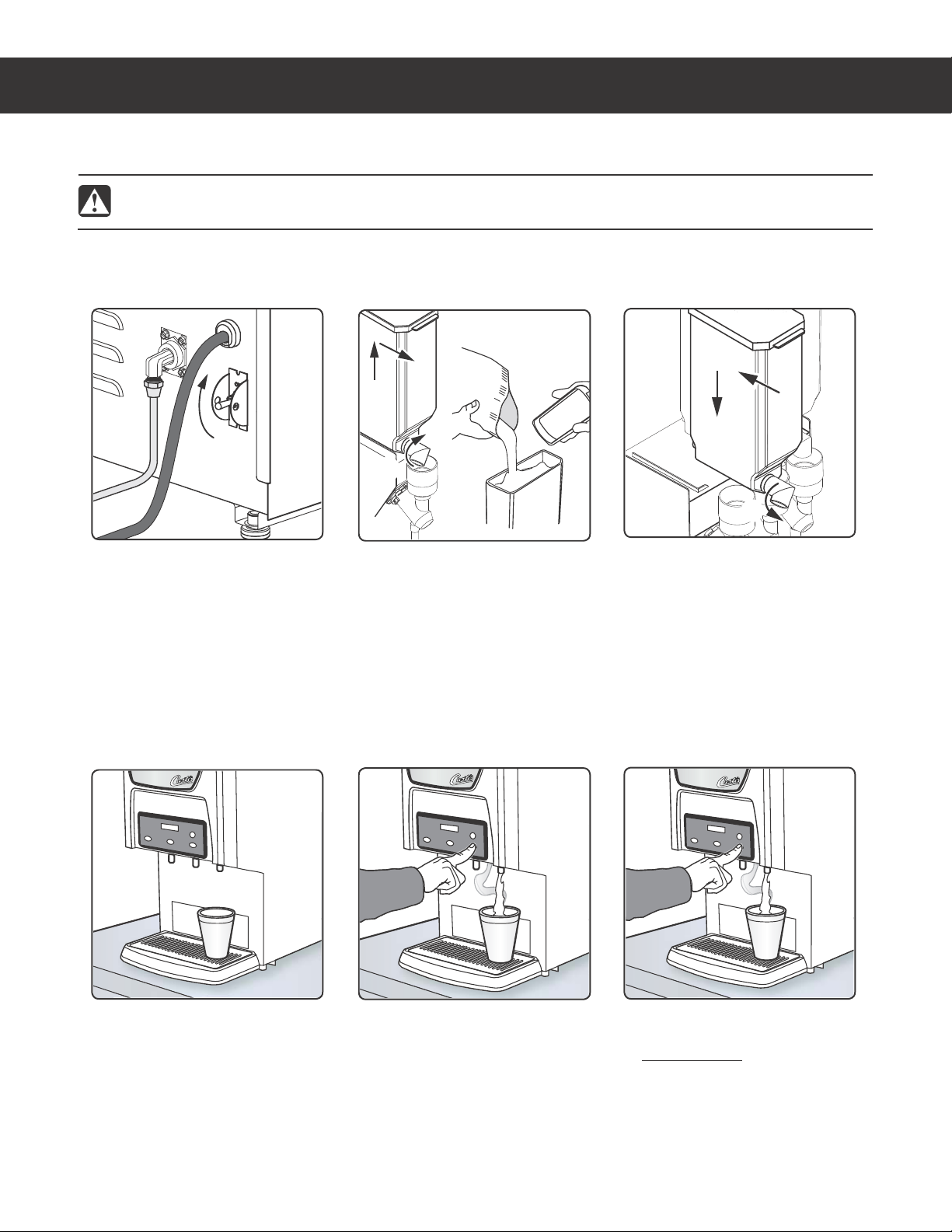
Dispensing
2 Open the front panel. On
some models the panel
swings to the right, on others,
the panel swings up. Turn
the elbow on each canister
UPCFmMMFEVQXBSEUIFOMJGU
each canister up and out. Fill
with powdered cappuccino
product.
Reinstall each canister in the
same spot it was removed
from. Properly mate the
gear socket on the back of
each canister with the gear
inside the dispenser. Turn the
canister elbows downward
and close the door.
4 Place a cup under the spout
GPSUIFEFTJSFEnBWPS*GUIF
dispenser is set for iced
DPGGFFmMMUIFDVQXJUIJDF
mSTU
Preset Dispense Models:
5 Push and release the
dispensing button for the
EFTJSFEnBWPSBOEDVQ
size. Remove the cup when
QSPEVDUTUPQTnPXJOH
The unit should be ON.
$POmSNUIJTBUUIFSFBSUPHHMF
switch. “Ready to Dispense”
should be on the display.
Manual Dispense Models:
6 Push and hold the dispensing
CVUUPOGPSUIFEFTJSFEnBWPS
Release the button when the
cup is ¾ full. Remove the cup
XIFOQSPEVDUTUPQTnPXJOH
WARNING - TO AVOID SCALDING, AVOID SPLASHING. Keep body parts clear of the spout during
dispensing. Do not remove the cup during dispensing.
The G3 dispenser is factory preset for optimal performance.
d
d
e
5B5A
c
c
e
WARNING: HOT SURFACES - To avoid injury, allow the dispenser to cool before cleaning.
1 Make sure power is ON.
2 Place a container under the dispense spout to catch the rinse water.
3 3JOTFFBDInBWPSCZQSFTTJOHBOEIPMEJOHUIF8"4)CVUUPOXIJMF
BUUIFTBNFUJNFQSFTTJOHPOFPGUIF164)EJTQFOTJOHCVUUPOT
POUIFDPOUSPMQBOFM$POUJOVFIPMEJOHUIF8"4)CVUUPOVOUJMUIF
water running from the spout runs clear.
NOTICE - Do not use cleaning liquids, compounds or powders containing chlorine (bleach) or corrosives.
5IFTFQSPEVDUTQSPNPUFDPSSPTJPOBOEXJMMEBNBHFUIFmOJTIFT USE OF THESE PRODUCTS WILL VOID
THE WARRANTY.
CLEANING INSTRUCTIONS CI19
Cleaning the Exterior - Daily
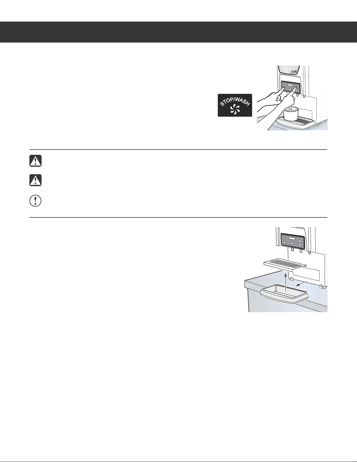
Spout Cleaning - Every 3 or 4 Hours
41&$*"-5:%*41&/4&3$-&"/*/(*/4536$5*0/4 "
WARNING: DO NOT immerse the dispenser in water or any other liquid.
The dispenser should be OFF.5VSOUIFCSFXFSPGGCZnJQQJOHUIFSFBSUPHHMF
switch to the OFF position.
1 8JQFUIFFYUFSJPSEJTQFOTFSTVSGBDFTXJUIBEBNQDMPUIUPSFNPWFTQJMMTBOE
debris.
2 -JGUUIFESJQUSBZVQUPSFNPWF3FNPWFUIFMPVWFSFEHSJMMGSPNUIFESJQUSBZ
UIFOXBTIPVUUIFUSBZXJUIUIFEFUFSHFOUTPMVUJPO8BTIUIFMPVWFSFEHSJMM
then rinse both pieces with water and dry.
3 8JQFBOEDMFBOUIFEJTQFOTJOHBSFBXJUIUIFEFUFSHFOUTPMVUJPOUIFO
reinstall the drip tray.

11 Reassemble the cleaned whipper assembly parts into the unit in
reverse order.
CLEANING INSTRUCTIONS CI20
CAFEPC, PCGT WHIPPER ASSEMBLY, CLEANING INSTRUCTIONS 120517NC
Cleaning The Whipper Plate Assembly CAFEPC and PCGT Series - Weekly or As Needed
The dispenser should be OFF. Turn the dispenser off by
turning the rear toggle switch to the OFF position.
1 Remove the dispensing spout from the whipper
chamber. Clean the inside using a narrow brush.
2 Pull the upper mixing cup forward and twist it up and to
the left to separate it from the lower mixing cup.
3 To remove the lower mixing cup, pull it up and forward to
free it from the hot water inlet.
4 Take hold of the whipper chamber. Turn it clock-wise to
free it from the mounting plate.
5 Pull the whipper propeller off of the motor shaft.
6 Wash, rinse, sanitize and air dry the whipper assembly
parts using the 3-sink method. Wash in a mild solution of warm water
and dishwashing detergent, rinse in warm clean water and sanitize in
a commercial sanitizer suitable for food grade applications. Sanitize
according to the directions on the package. Air dry all parts.
7 Clean the motor shaft with a cloth and mild detergent before
removing the mounting plate.
8 Twist the mounting plate clockwise and pull it off of the motor shaft.
IMPORTANT - Do not remove the mounting pillars to remove the
mounting plate.
9 $MFBOUIFBSFBCFIJOEUIFNPVOUJOHQMBUFBOEUIFXBUFSJOMFUmUUJOH
10 Lubricate the center seal of the mounting plate with food grade
lubricant before reinstalling (See Figure 3).
CAUTION: When replacing the propeller, line up the “D” shaped
mark on the propeller with the “D” shape on the motor shaft. Failure
to line up the propeller properly will cause it to fuse with the shaft.
This condition is not covered under the warranty.
WASH
SANITIZE
RINSE
Spout
Whipping
chamber
Propeller
Mounting
pillar
Mounting
plate
Motor Shaft
Upper
mixing
cup
Hot water
inlet
Lower
mixing
cup
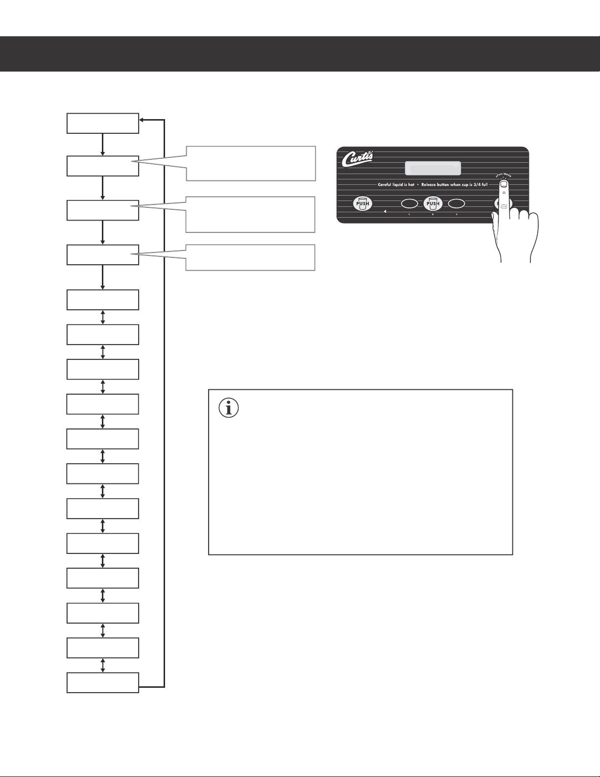
PROGRAMMING GUIDE PG12
With unit ON, press and hold
STOP/WASH button for 10
seconds.
While pressing STOP/WASH,
“Washing...Select Station”
appears on the display.
After 10 seconds, the
programming menu appears.
Label style and STOP/WASH
button location varies.
On PCGT6 models, the buttons
are located inside the front door.
1Not present on Pre-Set Dispense models
2Not present on PCGT6 series models.
1
1, 2
1, 2
1, 2
1, 2
CURTIS
Ready to Dispens
CURTIS
Ready to Dispens
Entering
Programming mode
Washing...
Select Station
To enter programming mode:
<Program Menus>
ÅSelect Æ
Manual Dispense
ÅSelect Æ
Dispense By Time
ÅSelect Æ
Temperature
ÅSelect Æ
Powder % Ratio
ÅSelect Æ
Dispense Odom.
ÅSelect Æ
Dispense Total
ÅSelect Æ
Service Call
ÅSelect Æ
Banner Name
ÅSelect Æ
Valve Calibrate
ÅSelect Æ
Model Select
ÅSelect Æ
Exit
ÅSelect Æ
Language
ÅSelect Æ
1$(5130(3"..*/((6*%&ø /$
IMPORTANT: All programming functions are performed with the
three center buttons.
The symbols below the buttons are:
Ż 4DSPMM61
~4&-&$5PS&/5&3UPTBWFOFXQBSBNFUFS
Ź4DSPMM%08/
Once you enter programming mode, press Żor Źto scroll UP or DOWN
through the various functions/features. Press ~4FMFDUUPNBLFDIBOHFT
to the function/feature displayed. Then press Żor Źto scroll through
the various available settings. See Programming Options for detailed
descriptions.

Programming Options
4FFUIFmSTUQBHFPGUIFPROGRAMMING GUIDE for instructions on how to access the programming menu.
To exit programming mode, press Źuntil EXIT appears on the display, then press ~.
Manual Dispense - All stations are set to Manual Dispense mode at the factory (except on Pre-Set Dispense
NPEFMT5IF.BOVBM%JTQFOTFQSPHSBNNJOHPQUJPOJTVTFEUPDIBOHFTUBUJPOTUIBUBSFTFUUP%JTQFOTF#Z
5JNFTFFCFMPXUP.BOVBM%JTQFOTFNPEF1SFTT~to access, then press the PUSH button for the station
to be set to Manual Dispense. “Saving Complete!” will appear on the display, then return to the programming
menu. Repeat the process to set other stations, if desired, or press Źto go to the next menu.
Dispense by Time - (default on Pre-Set Dispense Models) sets the unit
to dispense the amount of product by time rather than holding the button
until the desired amount is dispensed. Place a cup below the spout for
the desired station. Press ~to access. Press the PUSH button for the
TUBUJPOUPCFTFUUP%JTQFOTF#Z5JNF.BOVBM%JTQFOTFXJMMCFEJTBCMFE
GPSUIBUTUBUJPO5IFEJTQMBZXJMMSFBEi5P#FHJO1VTI164)w1VTIUIF
desired PUSH button. Hot water will start to dispense and the screen
will display “To Finish Push PUSH”. When the desired volume is reached
QVTIUIFCVUUPOBHBJO5IFEJTQMBZXJMMHPCBDLUPUIFQSPHSBNNJOHNFOV3FQFBUUIFQSPDFTTUPTFUPUIFS
stations if desired, or press Źto go to the next menu.
Temperature - TFUTUIFUFNQFSBUVSFPGUIFXBUFSIFMEJOUIFXBUFSUBOL5IFSBOHFJT'UP'¡$UP
¡$5IFSFDPNNFOEFEUFNQFSBUVSFGPSJDFEDPGGFFVOJUTJT¡'5IFSFDPNNFOEFEUFNQFSBUVSFGPSBMM
PUIFSVOJUTJT¡'¡$1SFTT~to access. Press Żor Źto choose the desired temperature. Then press
~to set and exit. Press Źto continue to the next menu.
Powder % Ratio - sets the ratio of product powder dispensed. The
higher the powder ratio, the richer the product dispensed. The factory
EFGBVMUTFUUJOHJT5IFSBOHFJTGSPNIPUXBUFSUP
HSBNTQFS1SFTT~to access. Press the PUSH button for the
desired station. Press Żor Źto increase or decrease the ratio, then
press ~to set and exit. Press Źto continue to the next menu.
Service Call - sets the service phone number that appears on the
display when the unit detects a SENSOR ERROR or WATER LEVEL
ERROR. Press ~to access. Press Żor Źto choose the number to be
changed. Then press ~repeatedly to change the number value. Press
Żor Źto choose the next number to change or choose ex and press ~
to exit. Repeat the process to set other stations, or press Źto go to the
next menu.
Banner Name - changes the banner name that appears on the display (the factory default is CURTIS/P
CBOOFSOBNFBQQFBSTXIFOBMMCMBOLTBSFFOUFSFE1SFTT~to access. Press Żor Źto choose the letter to
change. Then press ~repeatedly to change the letter. Press Żor Źto choose the next number to change or
choose ex and press ~to exit. Press Źto continue to the next menu.
Dispense Odom1, 2 - displays the total dispense cycles since the odometer was last reset. Press ~to access.
Press Żto exit or ~reset and exit. Press Źto continue to the next menu.
PROGRAMMING GUIDE PG12
1$(5130(3"..*/((6*%&ø /$
Default Settings Time Dispense Settings
Preset Dispense Models
Cup Size Time Setting
LARGE 25.5 Seconds
MEDIUM 16.5 Seconds
SMALL 12.5 Seconds
1Not present on Pre-Set Dispense models
2Not present on PCGT6 series models
% Ratio Grams*
10% 7 gm
20% 14 gm
30% 21 gm
40% 28 gm
50% 35 gm
60% 42 gm
70% 49 gm
80% 56 gm
90% 63 gm
100% 70 gm
*Approximate

PROGRAMMING GUIDE PG12
1$(5130(3"..*/((6*%&ø /$
Programming Options (cont.)
Dispense Total1, 2 - when accessed, displays the total dispense cycles on the unit. It cannot be reset. The
display returns to the previous screen automatically after a few seconds. Press Źto continue to the next
menu.
Language1, 2 - DIBOHFTUIFMBOHVBHFUIBUBQQFBSTPOUIFEJTQMBZUIFGBDUPSZEFGBVMUJT&OHMJTI1SFTT~
to access. Press Żor Źto choose the desired setting, then press ~to exit. Press Źto continue to the next
menu.
Valve Calibrate1-QPVSTXBUFSPOMZGSPNUIFTQPVUGPSTFDPOETUPBMMPXUIFEVNQWBMWFTUPCF
calibrated. See Dump Valve Calibration in the Troubleshooting Section for the complete dump valve calibration
procedure. Press ~to access. The bottom portion of the display will read “Select Station”. Place an empty
measuring cup under the dispensing spout for the valve to be calibrated. Press the PUSH button above the
DVQ8BUFSXJMMEJTQFOTFGPSTFDPOET1SFTT~UPNFBTVSFnPXSBUFGPSBEJGGFSFOUWBMWFPSQSFTTŹto
continue to the next menu.
Model Select1, 2 - changes the model number. The unit must be set to the proper model number for proper
operation. Press ~to access. Press Żor Źuntil the model number matching the model number label on the
unit appears, then press ~to exit. Press Źto continue to the next menu.
1Not present on Pre-Set Dispense models
2Not present on PCGT6 series models
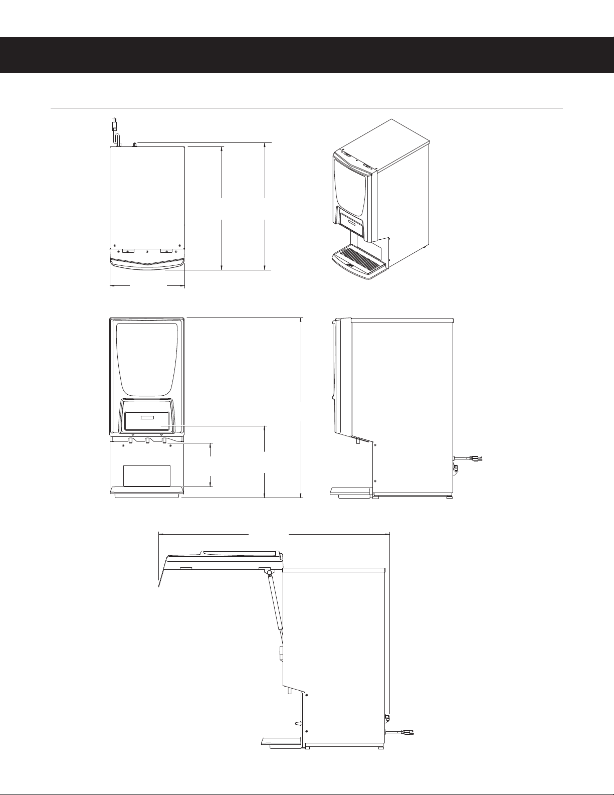
ROUGH-IN DRAWINGS RD46
PCGT3
PCGT3, ROUGH-IN DRAWING 061319B
14.25 in
[36.2 cm]
8.38 in1
[21.3 cm]
1CUP CLEARANCE
2DISPENCE BUTTON HEIGHT
13.94 in2
[35.5 cm]
34.78 in
[88.3 cm]
23.72 in
[60.2 cm]
24.54 in
[62.3 cm]
44.07 in
[111.9 cm]
LIFT DOOR
MODELS

ILLUSTRATED PARTS LIST IP75
PCGT3, ILLUSTRATED PARTS/RECOMMENDED PARTS 022519B
8
10
2
19C
2
14
13
19B
15
14
11
4
13
15
16
17
22
23
14
PCGT3300
PCGT3, PCGT3DV, PCGT3800
PCGT3700, PCGT3900, PCGT3E
MISCELLANEOUS
14
7
2
1A
1B 1D
20 10
21
19A
1C
20
8
8
6A
6B
6C
6D
9A
9B
9A
5
16
6A
6A
3A
3B
3C 3A
3A
12
PCGT3 - Door Assemblies - Exploded View
7
21
7
20
9A
21

ILLUSTRATED PARTS LIST IP75
PCGT3, ILLUSTRATED PARTS/RECOMMENDED PARTS 022519B
ITEM # PART # DESCRIPTION
1A CA-1184K1,2,4,6,7 KIT, DOOR ASSY PCGT3
(UNITS BUILT 08/01/11 AND LATER,
REPLACES CA-1172, CA-1101 & WC-37461)
1B CA-11581,2,4,6 DOOR/WINDOW SUPPORT PCGT3
(UNITS BUILT BEFORE 08/01/11)
1C CA-1184K13KIT, DOOR ASSY PCGT3300
(REPLACES CA-1172-101 & CA-1101)
1D CA-1184K25COVER, DOOR PCGT3800
(REPLACES CA-1172-102 & CA-1101)
2WC-39203 LABEL, SERVICING INSTRUCTIONS PC-
1/2/3/4D/CK-3D/HC-1D
3A CA-1109-011,2,3,5,7 FILM, CURTIS LOGO PCGT-3
3B CA-1148-014FILM, CURTIS LOGO PRE-DISPENSE PCGT3
3C CA-1144-016FILM, LIGHT BOX ICED COFFEE CURTIS
4 WC-380715LABEL, HOT WATER TLP/PC’s
5 WC-1705SWITCH, PUSHBUTTON-RED N.O. PCGT5 HOT
WATER KIT
6A WC-399581,2,3,5,6,7 LABEL, DOOR UCM PCGT3 CURTIS LOGO
(UNITS BUILT 08/01/11 AND LATER)
6B WC-397631,2,6 LABEL, UCM & DOOR PCGT3 CURTIS (UNITS
BUILT BEFORE 08/01/11)
6C WC-399774LABEL, UCM & OUTER PRE-SET DISPENSE
PCGT3 ADA (UNITS BUILT 08/01/11 AND
LATER)
6D WC-396184LABEL ASSY, UCM & DOOR PCGT3 WITH
PRE-SET DISPENSING CURTIS (UNITS BUILT
BEFORE 08/01/11)
7 CA-1176K* KIT, LAMP ASSY LED 120V 9W CAFEPC’s
ITEM # PART # DESCRIPTION
7 CA-1176K KIT, LAMP ASSY LED 120V 9W CAFEPC’s
Recommended Parts to Stock
ITEM # PART # DESCRIPTION
8CA-11011,2,4,6 WINDOW, FRONT CLEAR PCGT-3 (UNITS
BUILT BEFORE 08/01/11)
9A WC-7781,2,3,5,6,7 CONTROL MODULE, UCM 120V PCGTs
9B WC-7954CONTROL MODULE, UCM 120V EXPR/PCGT3
PRESET DISPENSE
10 CA-11351,2,4,5,6,7 LATCH ASSY, DOOR SIDE MOUNT PCGT’S/
CAFEPC’S/SD2’S
11 CA-10443BUMPER, BUTTON BLACK
12 WC-39350-02 LABEL, PANEL FLAVOR PCGT’S CURTIS
13 WC-49373GAS, SPRING 35LBS PCGT3300
14 WC-49333RECEPTACLE QUICK RELEASE GAS SPRING
15 WC-49313MOUNT, LOWER BALL STUD GAS SPRING
16 WC-49303MOUNT, UPPER BALL STUD GAS SPRING
17 WC-49353HINGE, ASSY DOOR PCGT5300
18 WC-134343HARNESS DOOR EXTENSION PCGT PCGT5300
(NOT SHOWN)
19A#CA-1184KDC1,2,4,6,7 KIT, DOOR COMPLETE PCGT3
(REPLACES WC-68165-101)
19B#CA-1184K1DC3KIT, DOOR COMPLETE PCGT3300
19C#CA-1184K2DC5KIT, DOOR COMPLETE PCGT3800
20 WC-4442 SCREW, 8-32x3/8 PH HD TRUSS BLACK
21 WC-4403 SCREW, 6-32x3/8 PHIL ROUND HD
22 WC-4468 SCREW, 8-32x5/8 PH HD TRUSS SS
23 WC-4426 SCREW, 8-32x3/8 PH HEAD TRUSS
ITEM # PART # DESCRIPTION
13 WC-4937 GAS, SPRING 35LBS PCGT3300
PCGT3 - Door Assemblies - Parts List
1PCGT3, 2PCGT3DV, 3PCGT3300, 4PCGT3700, 5PCGT3800, 6PCGT3900, 7PCGT3E
$OVRUHSODFHVÁRUHVFHQWDQGROGHUVW\OH/('OLJKWDVVHPEOLHVXVHGRQROGHUXQLWV
#&RPSOHWHGRRUDVVHPEOLHVLQFOXGHWKHSODVWLFIURQWDQGZLQGRZEXW'2127LQFOXGHWKH
8&0DQGOLJKWDVVHPEO\
ILLUSTRATED PARTS LIST IP75
PCGT3, ILLUSTRATED PARTS/RECOMMENDED PARTS 022519B
2
11A
4
5A
5B
6A
6B
11B
1A
1B
7
10
8
13
12
9
3A
3B
PCGT3 - Exterior - Exploded View
Door assemblies:
see previous pages

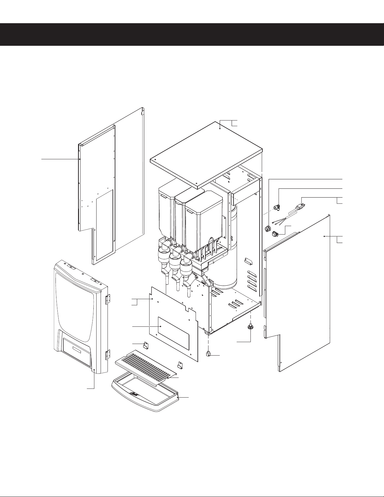
ILLUSTRATED PARTS LIST IP75
PCGT3, ILLUSTRATED PARTS/RECOMMENDED PARTS 022519B
ITEM # PART # DESCRIPTION
1A WC-581101,2,4,5,6,7 COVER, TOP PCGT3
1B WC-58110-1013COVER, TOP PCGT3300 FOR UNITS W/FRONT
LIFT DOOR
2 WC-68123 PANEL, SIDE LEFT PCGT3/5
3A WC-58351K1,2,3,4,6,7 KIT, ALCOVE PCGT3*
3B WC-58352K5KIT, ALCOVE PCGT3800*
4 WC-2401-P ELBOW 3/8 NPT X 1/4 FLARE PLTD
5A WC-681211,2,4,5,6,7 PANEL, SIDE RIGHT PCGT3/5
5B WC-68121-1013PANEL, SIDE RIGHT PCGT5300
6A WC-12001,2,3,4,5,6 CORD, 14/3 SJTO 6’ BLK W/PLUG
6B WC-1231-1027CORD, 2.5 mm² 90ºC 36A 450/750 V STRIPPED
W/FERRULES ONE END
ITEM # PART # DESCRIPTION
6 WC-1200 CORD, 14/3 SJTO 6’ BLK W/PLUG
Recommended Parts to Stock
ITEM # PART # DESCRIPTION
7 WC-3503 LEG, 3/8”-16 STUD SCREW BUMPER
8WC-68160 SCREEN, DRIP TRAY PCGT3
9CA-1160 DRIP, TRAY PLASTIC PCGT3
10 WC-3518 LEG, GLIDE 3/8”-16 STUD SCREW
11A WC-14081,3,4,5,6,7 CORD GRIP, 7/8” O.D.
11B WC-14122CORD GRIP, 3/4” FOR METAL CORD TO
.81”OD
12 WC-390503 LABEL, SPLASH PANEL CUP LOCATOR
PCGT3
13 WC-58274 RETAINER, DRIP TRAY PCGT6
ITEM # PART # DESCRIPTION
8 WC-68160 SCREEN, DRIP TRAY PCGT3
PCGT3 - Exterior - Parts List
1PCGT3, 2PCGT3DV, 3PCGT3300, 4PCGT3700, 5PCGT3800, 6PCGT3900, 7PCGT3E
,QFOXGHVODEHODQGGULSWUD\UHWDLQHUFOLSVLWHPVDQG

ILLUSTRATED PARTS/RECOMMENDED PARTS IP75
PCGT3, ILLUSTRATED PARTS/RECOMMENDED PARTS 022519B
15
4
5
6
8
7
23
37
38
13
PCGT3 - Interior Components - Exploded View
11
25
12
26
28
30
31
19A
19B
22
29
3A
3B
3C
2
32
33
10
34
27
21
1
39
36
24
9
17 35A
35B
20
14
Water tanks assemblies
- See section IP76 for single voltage models
- See section IP77 for dual voltage models
- See section IP80 for export models
18
This manual suits for next models
6
Table of contents
Popular Dispenser manuals by other brands


Sub-Zero
Sub-Zero BI-48SD Specifications

Royal Catering
Royal Catering RCSD-4 user manual

E-Pill
E-Pill MedSmart Voice Plus instruction manual

Gloria
Gloria CleanMaster PERFORMANCE CM 12 manual

Nordson
Nordson DispensGun user manual

AMERICAN SPECIALTIES
AMERICAN SPECIALTIES EZ FILL 0394 Series quick start guide