Wilderness Systems Commander Series User manual
WILDERNESS SYSTEMS
Commander Series Addendum

COMMANDER: GUIDE TO ADDITIONAL INFORMATION
Please refer to your Owner’s Manual for important information about your kayak.
The purpose of this guide is to help you make the best use of the additional
features and advantages that are unique to the Commander.
This owner’s manual and additional information is available at www.WildernessSystems.com
CONTENTS
3 Kayak Anatomy
4 Seating System
6 SlideTrax Accessory System
7 Angler Edition
8 Rudder Ready
9 Use and Installation of Trolling Motor
10 Transportation & Storage
11 SlideTrax Accessories
3
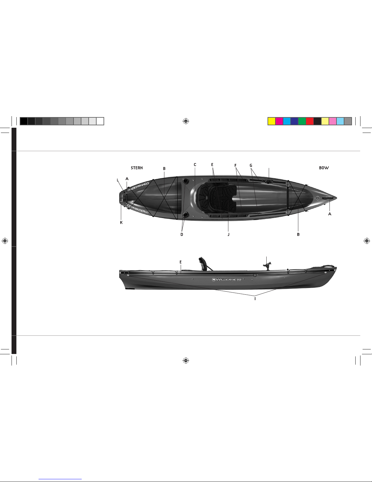
KAYAK ANATOMY
SIT ON TOP
A: Grab Handles
B: Tankwell with Bungee
C: Captain’s Seat
D: Flush Mount Rod Holders*
E: Side-Mounted SlideTrax Accessory System
F: Thigh/Knee Pad/Braces
G: Top-Mounted SlideTrax Accessory System
H: UMP with Rod Holder*
I: SlideTrax Anchor Trolley System*
J: Freedom Elite Seating System
K: Rudder ( Rudder Models Only)
L: Drain Plug
BOWSTERN
H
H
*Not available on all models/available on angler models

4
SEATING SYSTEM
REMOVING AND INSTALLING
THE FREEDOM ELITE SEAT:
REMOVAL:
1. Release the Lock Down System (see Freedom
Elite Lock Down System section).
2. Lift the seat off the side runners and rotate seat
90oso it is perpendicular to the center line of
the boat (sideways) and lift out of boat.
INSTALLATION:
1. Place the seat, oriented sideways, into boat
between the two side runners.
2. Lift the seat slightly so that the sides of
seat can slide between the deck and the
side bars; then rotate seat so it faces towards
bow of boat.
3. Snap the seat onto the seat bars by pushing
down on seat and then slide to desired
position.
4. When desired position is reached, use the
Lock Down System to secure seat into place
(see Freedom Elite Lock Down System section).
FREEDOM ELITE LOCK DOWN SYSTEM
The system is designed to secure the sliding
Freedom Elite Seat in a preferred paddling position
and to lock the seat in place when transporting the
boat on your vehicle.
KEY COMPONENTS:
The sliding seat snaps over tubular bars underneath
the side decks. Running above and outside the each
tube is a length of static cord. Mounted on each
side of the seat are horizontal “clam” cleats.
TO RELEASE SEAT SO YOU CAN SLIDE
OR REMOVE:
1. Grasp the black static cord on each side of seat
and pull it free of the clam cleat on each side.
2. Slide seat forward or backward as desired.
3. Relock seat when desired position is achieved.
The Commander features a dual-seating system:
a unique, removable sliding seat and a secondary
Captain’s seat molded into the deck behind the
sliding seat.
The sliding seat features a lock-down system that
secures it into a desired position, angle-adjustable
padded backrest and leg support for maximum
customized comfort to accommodate paddlers of
various sizes.
The interior sliding seat (referred to as the Freedom
Elite Seating System) is also designed to be
removed from the hull, allowing it to be used as a
“beach” chair on shore or just about anywhere.
Removing the seat will also lighten the boat by
about 6 lbs. to make it easier to load your boat on
and off a vehicle.
NOTE:
The sliding seat should always be in the locked
position when transporting the boat with the
seat installed.

5
SEATING SYSTEM
TO LOCK DOWN YOUR SEAT ONCE YOU
HAVE POSITIONED IT AS DESIRED:
1. Pull the black static cord out towards side of boat
and then push it into the jaws of the clam cleat so
the cleat grabs and locks cord in place.
USING THE CAPTAIN’S SEAT
Located on deck—just behind the sliding seat
well—is an ergonomically shaped recess designed to
provide an elevated paddling and fishing position
for improved visibility and comfort. For maximum
leg room and accessibility, you should stow the
Freedom Elite Seating System below the captain’s
seat by doing the following:
1. Release the sliding seat lock down system.
2. Fold seat back down so that it lays flat on seat.
It is not recommended to sit on the seat back
when in this position.
3. Slide the seat backwards so that it tucks under
the deck. This provides access to sit on the
Captain’s Seat.
ADJUSTING ANGLE OF BACKREST:
1. Locate the strap running through backrest
and ending on each side of seat pan with a
webbing buckle.
2. Release tension on buckle to allow seat back
to assume a more relaxed or reclined position.
3. To bring seat back to a more upright position,
tighten straps through the buckles.
ADJUSTING LEG LIFTER:
1. Locate the strap on either side of seat
connected to the leg-lifter thigh support
system. This strap also routes through the
backrest.
2. Lift legs off the seat and tighten strap to raise
the leg-lifter for more support when your knees
are bent.
3. Loosen strap to relieve support when you
desire a more relaxed position.
ADJUSTING THE FREEDOM ELITE SEAT
FOR COMFORT
The Freedom Elite seat in the Commander features
textured molded foam for maximum comfort and
ventilation. The system also features an adjustable
angle backrest and adjustable leg lifter for thigh
support.
Adjustments are made via straps on either side of
the seat. One strap controls the angle of the
backrest and the other provides adjustment in leg
support.
When making adjustments, it is best to relieve the
weight placed against the component being
adjusted. For example, if you are tightening or
loosening the back rest, lean forward and get your
weight off the backrest while doing so. If you are
raising or lowering the leg lifters, lift your legs off
the pads while making the adjustment.
By removing tension on the backrest strap, the leg
lifter and backrest will move together, providing
support to the paddler in a variety of reclined or
upright positions. Tensioning the backrest strap will
provide a firm backrest which some paddlers may
find preferable depending on conditions.

6
SLIDETRAXTM ACCESSORY SYSTEM
One of the most appealing and useful features
on the Commander is the dual SlideTrax System—
a modular, movable accessory outfitting system.
One set of SlideTrax rails is positioned on top of
the deck in front and a second set runs along the
side of hull from bow to stern on each side.
Accessories can be installed, removed, or
repositioned as desired. They attach to the
SlideTrax via a screw and rectangular plate
captured within the track.
Each Commander comes standard with dual
adjustable bow and stern bungee cord systems.
The bungee cord is routed through unique SlideTrax
Fittings that have holes to allow line to be pushed
through for maximum security and are “hooked” as
well so that they capture line that is looped under
them. Each fitting is also removable or can be
repositioned as desired by loosening the socket
head screw with a 3/16” hex wrench.
On the stern bungee system the cord is looped
under the center fitting on each side rather than
through the eyelet on the fitting. This allows you to
open up the tankwell completely by simply
unhooking the bungee from the center fittings and
letting it fall open, providing complete access to
tankwell.
INSTALLATION OF ACCESSORIES ON
TOP-MOUNTED SLIDETRAX RAILS:
1. Remove base plates from screws on
accessory and slide plates into desired
track from forward end of track.
2. Align screws over base plates and start
each mounting screw into threaded hole
in base plate.
3. Slide accessory to desired position and
tighten securely.
To see the complete line of SlideTrax
accessories, visit www.HarmonyGear.com
INSTALLATION OF ACCESSORIES
ON SIDE SLIDETRAX RAILS:
1. Use a Phillips screwdriver to remove screw
holding the rail end cap at bow of boat to
insert base plates for bow-positioned
accessories. At stern end, it will be necessary
to reach inside of boat to hold rubber wellnut
while removing screw. Retain hardware for
reinstallation of end cap.
2. Remove base plates from screws on accessory
and slide plates into rail. It may be necessary,
depending on accessory and desired position,
to loosen or move existing fittings on the rail.
You may find it more convenient to unscrew the
bungee fittings from the SlideTrax rail and move
the brass plate forward or back to position
desired for new accessory and then slide new
brass plate into position for bungee fittings.
3. Align screws over base plates and start each
mounting screw into threaded hole in base
plate.
4. Tighten securely when desired position for
accessory is determined.
5. Replace end cap on end of rail with original
hardware.

7
ANGLER EDITION
COMMANDERS ARE AVAILABLE IN
AN ANGLER EDITION THAT COMES
STANDARD WITH:
•2 flush mount rod holders located behind the
Captain’s Seat.
•SlideTrax Universal Mounting Plate (UMP) on top
rails with Scotty Baitcaster Rod Holder.
•Anchor Trolley System
• Installed motor mount block to accommodate
electric trolling motors up to 54 lbs thrust.
(See guidelines for motor use on page 9)
• (2) 10” x 10” Silent Traction Pads. To see more
Silent Traction Pads and common uses, visit the
fishing gear section on www.HarmonyGear.com
TO INSTALL UMP WITH ROD HOLDER:
1. Choose which side of the top mounted SlideTrax
you want to use for rod holder.
2. Unscrew brass plates from base of UMP and
insert into bow end of selected track.
3. Align screws over brass plates in track and
thread into brass plates. Tighten securely with
Phillips screwdriver.
ANCHOR TROLLEY SYSTEM
The SlideTrax Anchor Trolley System is mounted on
one side of hull. This system can be repositioned to
other side of hull if desired. The system features two
pulleys to provide smooth easy operation, a 2”
nylon ring to accommodate use of a setting pole in
shallow waters with sandy soft bottoms, and a
stainless carabiner to serve as a guide or fairlead for
your anchor line.
Use caution as you become accustomed to your
anchor trolley system and pay attention to water
and weather conditions while in use.
Sudden changes in conditions could make
anchoring at a selected location or orientation
hazardous as well as make it difficult to retrieve
anchor safely.
TO SET UP YOUR ANCHOR
TROLLEY SYSTEM:
1. Use a Phillips screwdriver to remove screw
holding the rail end cap at bow of boat to
insert base plates for bow-positioned
accessories. At stern end, it will be necessary to
reach inside of boat to hold rubber wellnut
while removing screw. Retain hardware for
reinstallation of end cap.
2. Install three (3) SlideTrax fittings on side rail.
One will be placed at each end of track to serve
as end points for trolley system and the other is
to be positioned just behind seat and will serve
as a lock down for trolley when you determine
desired deployment of anchor. You may have to
loosen and remove any SlideTrax fittings in
place between end of rail and desired location
for this fitting. Note that fitting has one side
more rounded than the other. Orient fittings so
that rounded side faces down.
3. Remove brass plate from fitting, insert into end
of rail and slide to desired position. Align end
of screw in SlideTrax fitting over brass plate
and tighten securely.
4. Install two (2) SlideTrax fittings near each end of
side SlideTrax rail, orienting molded fittings so
that lacing hole in fitting faces down. Re-install
the end caps on ends of rail.
5. Thread 12” of static cord through SlideTrax
fitting and through top bar on pulley. Tie off
securely. Singe end with lighter or matches
to prevent fraying. Repeat for opposite end of
boat.
6. Thread balance of static line through pulleys
and bring ends to center of boat. Adjust line so
that ends are equal. Route cord so that it runs
under the SlideTrax rail. The other SlideTrax
fittings installed on the rail will help guide and
retain the cord.
7. If desired, a length of elastic bungee cord is
provided to allow for adjustable tension in the
trolley cord. This can be eliminate or minimize
slap of the trolley system against hull of boat
potentially frightening fish. If you wish to use
this feature, tie off bungee cord into a loop.
Push end of loop around 2” setting pole ring
and feed opposite end of bungee loop through
it so that ring is captured. If you opt to dispense
with bungee loop, simply tie off end of cord to
the setting pole ring.
8. Loop one end of cord through opposite end of
bungee cord loop and tie off securely.
9. Run opposite end of cord through base of
carabiner. Clip carabiner to setting pole ring and
draw cord to desired tension. Cord should be
taut enough to tension the pulleys against the
bungee cord but not drum tight. Tie off cord to
carabiner with secure knot such as a bowline
and cut off excess cord. Singe end with lighter
or matches to prevent fraying.
10. You can move the position of the setting pole
ring and carabiner forward or back along hull by
pulling on cord next to seat. To lock position on
hull, grasp line and wrap around the SlideTrax
fitting installed earlier.

8
RUDDER – READY COMMANDERSANGLER EDITION
11. Take running end of anchor rode (line) and clip
through carabiner on anchor trolley line.
12. Secure end of anchor rode onto horn cleat next
to Captain’s Seat.
13. Unwrap anchor trolley line from SlideTrax fitting
so that you can position angle and location
anchor will run from its’ set to your boat. This is
achieved by guiding anchor line where it runs
through carabiner to move forward or back
alongside of hull. Once position is determined
re-wrap trolley line down around SlideTrax fitting
next to seat to lock in position.
14. The round ring to which the carabiner is
attached is designed to anchor a setting pole,
often used as an anchor in shallow, sandy
bottoms. Simply push your setting pole through
the ring to hold your boat in place.
RUDDER – READY COMMANDERS
If your Commander was not ordered with factory
installed rudder, Wilderness Systems has made it
easy to change your mind. All Commanders are
shipped rudder-ready. The tubes running
underneath the deck that contain and guide the
rudder cables from stern to footpedals are factory
installed as are inserts to mount a rudder bracket to
stern.
To install a rudder on your Commander, you will
need to order a BTS Rudder Ready Kit (#8025416)
which includes all necessary components to install
a rudder. Minor drilling of deck is required for
installation.
(Visit www.HarmonyGear.com)

9
USE AND INSTALLATION OF TROLLING MOTOR
• All wires should be secured inside of hull.
Loose wires pose a potential entrapment
hazard if left unrestrained in hull.
• The use of a battery box is recommended.
Secure the battery box to the hull of kayak
and place battery inside box. This will minimize
chances that battery could flip over and
possibly leak.
• Should any battery acid leak onto hull, clean up
thoroughly as quickly as possible so that acid
will not damage hull.
• Operation of motor and controls should be
thoroughly tested under controlled conditions
before using. Choose a calm, shallow, area to
become familiar with your Commander when
under power. Test all functions and speeds of
motor and effect on kayak so that you can
anticipate how the boat will respond when in
normal use. The presence of an additional
person to assist during trials is recommended.
• Follow closely all instructions provided by the
motor manufacturer when installing, using, and
removing your motor and components.
The Commander Series Angler editions come
standard with a molded motor mount to accept
electric trolling motors. A motor mount kit is
available for other Commander models which can
be easily installed. This requires drilling of two
holes at marked locations in the transom of the hull.
The Commander Motor Mount kit provides a
molded motor block, hardware and instructions.
Please keep the following recommendations
in mind should you decide to install an electric
trolling motor:
• It will be necessary to remove the rudder bracket
from stern of Commander if you choose to use a
motor rather than a rudder.
• Electric trolling motors of 54 lbs thrust or less
are recommended. Use of a gasoline motor is
not recommended.
• Confirm fit of transom clamp on motor with
transom on Commander. Motor should be able
to be clamped securely to the transom so that
as motor is rotated or lifted or deployed there
is no movement at point of contact.
• The use of a tiller extension is recommended.
• The use of an extended wiring harness is
recommended to allow battery to be positioned
in bow tank well of Commander for best balance
and trim. Many batteries are as heavy as the
motors and it is recommended to position them
at opposite ends of boat for proper trim.
THE FOLLOWING PRACTICES ARE
NOT RECOMMENDED:
• The use of a side-mounted motor is not
recommended on the Commander.
• Use of a gasoline motor is not
recommended.
• It is not recommended to sit behind the
Captain’s seat when operating motor.
This will result in improper trim and can
affect stability and performance of
Commander.

10
TRANSPORTATION & STORAGE
Due to the unique hybrid design of your Wilderness Systems Commander kayak, there are special
transportation and storage requirements to ensure the boat maintains its structural integrity.
Please note that these differ from our standard kayak storage and transportation guidelines.
SPECIAL TRANSPORTATION NOTICE FOR COMMANDER SERIES
DO NOT transport a Commander kayak upside down.
RECOMMENDED TRANSPORT OPTIONS:
• Placing Commander right-side up on a flat surface or using roof racks. Supports should be at
least 48 inches apart.
• Placing Commander on its side on a flat surface or using roof racks. Supports should be at least
48 inches apart.
• Use caution with roof racks that have bars or supports close together. Supports should be at
least 48 inches apart. Also ensure that there is not significant tension pulling down on either
the bow or stern.
SPECIAL STORAGE NOTICE FOR COMMANDER SERIES
DO NOT store a Commander kayak upside down.
DO NOT suspend the Commander by the carrying handles at each end.
RECOMMENDED STORAGE OPTIONS
• Place Commander right-side up on flat surface. If using supports they should be at least 48
inches apart. Avoid putting the weight of the Commander primarily on the bow and stern ends
by placing supports approximately half the distance from the center of the kayak to the ends
on each side.
• It is not recommended to suspend the Commander using web straps. In the event this must be
done, the kayak should be suspended on its side or right-side up, with support straps located at
least 48 inches apart. Also ensure that there is not significant tension on either the bow or stern.
OK
OK
OK
OK

SLIDETRAX ACCESSORIES
NOTE:
If you purchased an Angler version of the
Commander, the UMP with Baitcaster Rod
Holder (#8025129) and Anchor Trolley System
(#8025126) come standard with your boat.
There is an ever-growing list of modular
accessory options designed to exploit the
advantages of SlideTrax. To see full line of
accessories, visit www.HarmonyGear.com.
TOP-MOUNTED SLIDETRAX:
Dashboard (#8025345) and Wide Dashboard
(#8023068)–will accommodate multiple rodholders,
fishfinder bases, GPS, etc., as well as is easily
drilled for custom applications.
Toolboard (#8025346)–attaches to the dashboard
and provides stowage and organization for your
most needed tools and accessories.
Sideboard (#802523)–a compact flat plate that can
be attached to either side of hull, providing more
mounting options for select or custom accessories
and is complemented by a Transducer Deployment
Arm/TDA (#8025242) that solves the often tricky
challenge of how to rig the transducer on fish
finders, depth finders, etc.
Universal Mounting Platform/UMP (#8025239)–
provides a compact but secure mounting surface,
predrilled to accept the most popular Scotty and
Ram Mount rod holder base systems. It is also
available in combination with a Scotty Baitcaster
Rod Holder (#8025129).
SIDE-MOUNTED SLIDETRAX:
Utilize to secure the adjustable bungee cord
systems standard on each Commander. In addition,
they will accept and support the installation of:
Commander Bow and Stern Bag/Covers (120 &
140 Bow - #8023013);(Stern 120 - #8023014);
(Stern 140 - #8023015)–Multi-purpose bags
tailored to fit in the bow and stern cargo wells of
the Commander, providing storage and
organization for all your gear within mesh storage
compartments below the covers. A hidden
half-moon zipper provides easy access for bulky
items and minimizes leakage from spray or rain.
The top decks of the bags are designed to serve as
water-resistant spray covers for the cargo wells,
overlapping the sides of the hull and attaching to
boat via the adjustable SlideTrax Fittings supplied
with the bags.
Anchor Trolley System (#8025126)–allows you to
secure and anchor without drilling holes in your hull.
Anchored at each end of hull by adjustable
SlideTrax fittings, the Anchor Trolley System allows
anglers and paddlers to anchor and position their
boats relevant to current, wind, or tide to maximize
safety and opportunity.
Silent Traction Pads (#8023363) and Silent
Traction System (#8023362)–reduces the noise
transmitted through the water caused by incidental
contact with the hull by paddles, poles, pliers and
other fishing necessities as well as additional
traction when standing.
11

59504168
©2011 Confluence Watersports
SlideTrax is a trademark of Confluence Watersports
Confluence Watersports
575 Mauldin Road, Suite 200
Greenville, SC 29607
www.WildernessSystems.com
Table of contents
Other Wilderness Systems Boat manuals


