Williams AV AMPETRONIC MLD9 System manual

MLD9
Installation Handbook
www.williamsav.com
www.ampetronic.co


Handbook Contents
• Safety
• Introduction
• Quickstart
• Installation
• Overview
• Troubleshooting
• Accessories
• Technicalspecications
• Warranty
• Declarationofconformity
Box Contents
• 1xMLD9
• 2xLoopconnector
• 1xStatusconnector
• 1xDCconnector
• 1xInstallationhandbook
• 2x2mmsteel1Urackmountbrackets
• 1xPowercable(regionsspecic)
• 1xInductionLoopSign
This symbol is used to alert the user to important
operating or maintenance instructions.
The Lightning bolt triangle is used to alert the user
to the risk of electric shock.
SAFETY
1. Itisimportanttoreadtheseinstructions,andtofollowthem.
2. Keepthisinstructionmanualinanaccessibleplace.
3. Cleanonlywithadrycloth.Cleaninguidsmayeffecttheequipment.
4. Donotblockanyventilationopenings.Installinaccordancewiththemanufacturer’s
instructions.
5. Donotinstallthisequipmentnearanyheatsourcessuchasradiators,heatingventsorother
apparatusthatproducesheat.
6. WARNING–THISAPPARATUSMUSTBEEARTHED/GROUNDED.
7. Onlypowercordswiththecorrectpowerconnectormaybeusedtomaintainsafety.Cables
incorporatingtheUK13Afusedplug,SchukowithearthingcontactsandULapproved
“groundingtype”areacceptable.Thesemustbepluggedintopoweroutletswhichprovidea
protectiveearth.
8. Referallservicingtoqualiedpersonnel.Servicingisrequiredwhentheapparatushasbeen
damagedinanyway,suchasapowersupplycordorplugisdamaged,liquidhasbeenspilled
orobjectshavefallenintotheapparatus,theapparatushasbeenexposedtoanyrainor
moisture,doesnotoperatenormallyorhasbeendropped.
9. WARNING–Toreducetheriskofreorelectricshock,donotexposethisapparatusto
rainormoisture.Theapparatusshallnotbeexposedtodrippingorsplashingandno
objectslledwithliquids,suchasvases,shallbeplacedontheapparatus.
TO PREVENT ELECTRIC SHOCK DO NOT REMOVE THE
COVER. THERE ARE NO USER SERVICEABLE PARTS
INSIDE. REFER SERVICING TO QUALIFIED PERSONNEL
Ampetronic MLD9 Installation Handbook Page 1

Introduction
TheMLD9Inductionloopdriverhasbeendesignedasahighqualitydualchannelamplierforuse
withmultiplelooporPhasedArrayloopdesigns.
AnArraySystemprovidesasolutionwhereasimplelooparoundtheroomperimeterwillnotwork.
Arraysarethestandardsolutionforbuildingswithmetalstructureorreinforcements,orforcovering
largeareas.Arrayscanalsodramaticallydecreasethe‘spill’ofthemagneticsignaloutsideofthe
room,allowinginductionloopstobeinstalledinadjacentrooms,andprovidinganimprovedlevel
ofcondentiality.Arrayscanalsobeusedtochangethewaytwoloopsinterferewitheachother,
providingwaysofsolvingeventhemostcomplexinstallationproblems.
Dependingonanumberoffactorsregardingtheinstallationoftheloopandtheset-upofthe
ampliertheMLD9canprovidecompliancewithIEC60118-4forperimeterloopareasofupto2x
1,300m2orphasedarraysystemsupto3,300m2.
Easeofinstallationandusehavebeenmajorfactorsinthedesign,combinedwithoptimised
performance,andthefreedomfromR.F.I.generation.
TheMLD9stwooutputchannelscanbeconguredwithorwithout90°ofphaseshiftbetween
thetwo,allowingtheuseofarraysystemsortwoseparateloopswiththesamesignaltherefore
doublingtheareacoverage.
TheMLD9hastwobalancedinputs.Thesecanbeconguredformicrophoneorlineinputswith
individuallyselectablephantomandgainboost.
Formorecomplexinstallations,youmayneedancillaryequipmentsuchasmicrophonepre-
amplier(s),adaptor(s)forusewith100Vline,orsignalprocessingunits.SeeAccessoriesor
contactAmpetronicforadvice.
QUICK START
Forthosewhohaveagoodappreciationofloopsystems,thefollowingisaveryquickguideto
settinguptheamplier:Allyouneedisanacpowersource,asignalsourceandaPhasedArray
looppair.See‘DesigningInductionLoops’handbook(supplied)orcontactAmpetronicforadvice.
Installation
a.Turnallcontrolsfullyanti-clockwise.
b.Connectloopcables.
c.Connectsignalinput(s).
d.Connectpower.Seepoints6and7inSAFETYsection.
e.Ifrackmountedremoveallrubberfeetfromunits.DONOTre-tthefeetxingscrewsasthis
maycausedamageandinvalidatethewarranty
Operation
1. SwitchON–check‘earsymbol’ashesduringselftestandilluminatescontinuouslywhen
checksarecomplete.
2. ApplyinputsignalandincreasetheinputcontroluntiltwogreenCOMPRESSIONLEDsare
illuminatedonthepeaksofthesignal.
3. Selectphaseshiftrequired0or90°.
4. AdjusttheCURRENTcontrolsuntiltheCURRENTLEDsilluminatetoachievethedesired
peakcurrents.
5. Repeatstep2foranyotherinputsused.
6. Listentothemagneticeldproducedinsidetheloopareausingareceivingdevice(e.g.
AmpetronicILR3),orexaminetheperformanceinmoredetailwithaeldstrengthmeter.
7. AdjustMLCcontroltoachieveaatfrequencyresponse.
Ampetronic MLD9 Installation HandbookPage 2

CONNECTIONS
Inputs
Screen
- (Signal cold)
+ (Signal hot)
Connection of balanced
male XLR
1- 1+
2+ 2-
1- 1+
2+ 2-
LOOP
1-
2-
1+
2+
Outputs
Screen
- (Signal cold)
+ (Signal hot)
Connection of balanced
male XLR
1- 1+
2+ 2-
1- 1+
2+ 2-
LOOP
1-
2-
1+
2+
Screen
- (Signal cold)
+ (Signal hot)
Connection of balanced
male XLR
1- 1+
2+ 2-
1- 1+
2+ 2-
LOOP
1-
2-
1+
2+
1=TwistedPair,2=QuadCore
Refertotechnicalspecicationsforconnectiondetails
BLOCK DIAGRAM
Ampetronic MLD9 Installation Handbook Page 3

INSTALLATION
Location
Theunitmaybefreestandingor19”rackmountableusingtherack‘ears’supplied.Fittingofthe
‘ears’isachievedbyremovingthethreeforwardmostscrewsonbothsides.Thesamescrews
arethenre-usedtosecurethe‘ears’inplace.(APH2screwdriverwillberequired).For19”rack
mountingthefourrubberfeetmustberemoved.
Thelocationmustprovideadequateventilationfortheunit.
Internalfansprovideforcedventilationusingairventsatthefront(intake)andrear(exhaust)ofthe
unit.Theseventsmustbeunobstructedforsatisfactorycooling.Iftheunitisinstalledinanenclosed
environment,sufcientairowintotheenclosuremustbeprovidedthroughvents,fansorother
means,suchthattheunitsexhaustairisnotrecycledtotheinlet-causingareductioninoutput
currentorOVERHEATLEDtobeilluminated.
ContactAmpetronicforadviceoncoolingrequirementsforyourinstallation.
Tools and Equipment
Smallhandtoolsincludingawirestripperandasmallatbladescrewdriverwillberequired.
AnILR3loopreceiveroramagneticeldstrengthmeterisvitaltocheckthattheloopsystemis
providingthedesiredlevelofperformance.
Apairofstereoheadphoneswitha3.5mmjackplugconnectionisalsousefultomonitortheloop
signal.
System Requirements
Theinductionloopcablesshouldbealreadyinstalledaccordingtothe‘DesigningInductionLoops’
handbook,orasperspecicdesigninstructionsprovidedbyAmpetronic.Asaresult,atarget
currentshouldbeknown,basedonachievingacceptableeldstrengthacrosstheareatobe
covered.
Inordertoachievecorrectoperationitisrecommendedtheloopandfeedresistanceshouldbe
between0.5and3Ω(atDC).ValuesoutsidethismaycausetheLOOPERRORLEDtoilluminate
andtheampliersoutputtobedisabled.Loopandfeedimpedance(at1.6KHz)shouldbelessthan
thevoltagecapabilityofthedriverdividedbythetargetcurrentrequiredtoachieveeldstrength.
ValuesabovethisguremaycausetheCLIPLEDtoilluminate.Seetroubleshootingsectionfor
adviceonhowtocorrectthisandgetyoursystemworking.
The‘DesigningInductionLoops’handbookcontainsmoredetailsonloopandfeedcables.The
correctdesignandpositioningoftheactualloopisvitalforsatisfactorysystemperformance.Ifin
doubtconsultAmpetronicforadvice.
CONNECTION & SET-UP
ItisadvisedthattheloopsystemisinitiallysetupusingalocalaudiosourcesuchasaCDplayer,
whichisnotconnectedintoanyothersystem.Thisavoidsthecomplicationofgroundloopsand
feedbacketc,whilsttheunitissetup.
Thefollowingproceduredescribestheinstallationofastand-aloneMLD9,anddoesnotincorporate
connectionofotherancillaryunitssuchasmicrophonepre-amps,mixingdesks,orsignal
processingunits.
1. Turnallcontrolsfullyanti-clockwise.
2. ConnectthefeedcablesfromtheloopsintotheNL4loop
connectorssuppliedasshown:
Screen
- (Signal cold)
+ (Signal hot)
Connection of balanced
male XLR
1- 1+
2+ 2-
1- 1+
2+ 2-
LOOP
1-
2-
1+
2+
Ampetronic MLD9 Installation HandbookPage 4

Note: To avoid unwanted stray magnetic elds the feed cable should be tightly twisted or star-
quad connected.
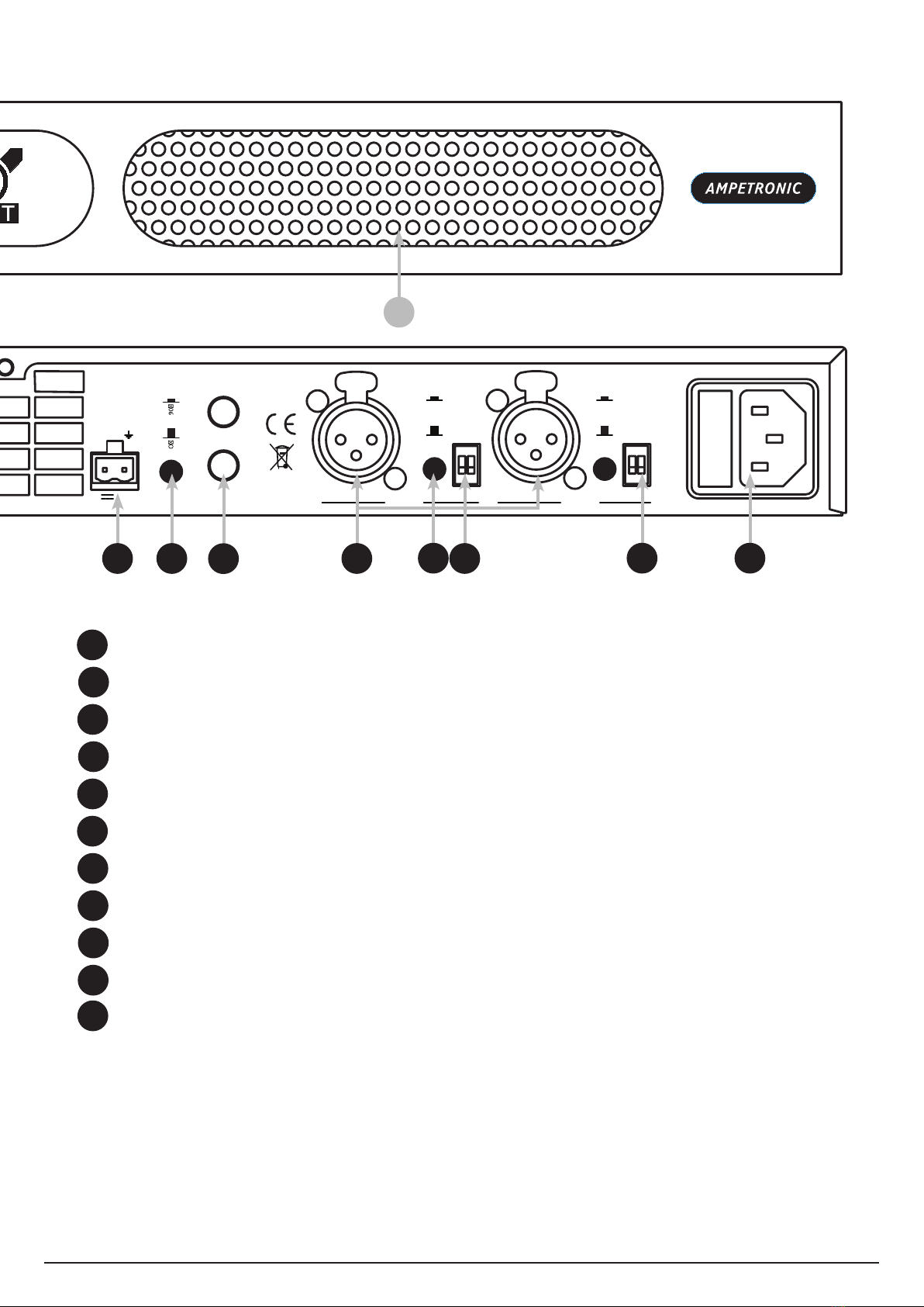
3. Connectthesignalinputsappropriately:
Microphones:Suitabledynamicorcondensermicrophonewithbalancedcablefeed.Select
phantompowerasrequired.ConnecttoINPUT1andINPUT2(withselectorswitchesinthe
appropriateposition)usinga3-poleXLRplugwiredasperConnectionsdrawing.
Linelevelsignals:FromotheraudioequipmentsuchasPAsystem,mixingdeskorCDplayer.
ConnecttoINPUT1andINPUT2(withselectorswitchesintheappropriateposition)usinga
3-poleXLRplugwiredasperConnectionsdrawing.Youmayuseeitherorbothinputs.
Donotruninputandoutputcablesclosetogether
4. ConnectACpowertotheMLD9.Seepoints6and7inSafetysection.
5. SwitchON.The‘ear’symbolwillashforafewsecondswhilstaninternalself-testisperformed
andtheloopresistanceistested.Ifbothtestsaresuccessful,the‘ear’symbolwillilluminate
continuouslyandtheunitwillbeinanoperationalmode.Ifthe‘ear’symbolcontinuestoash,or
oneorbothLOOPLEDsilluminate,consulttheTroubleshootingsection.
6. Selectoneinputandapplyasuitableaudiosignal(ideallyaCDplayerwithmusicorcontinuous
speechappliedtooneinput,withnoconnectiontotheother).Turntheassociatedinputcontrol
clockwiseuntiltwoCOMPRESSIONLEDsareilluminatedonthepeaksofthesignal.
7. TurnCHACURRENTcontrolclockwiseuntilthetargetcurrentisachieved–asindicatedby
theCHACURRENTLEDs.NotethatconsecutiveLEDsilluminateat3dBintervals.TurnCH
BCURRENTcontrolclockwiseuntilthetargetcurrentisachieved–asindicatedbytheCHB
CURRENTLEDs.HeadphonescanbeusedwiththeMONITORsockettolistendirectlytothe
loopcurrent.NOTE:channelAoutputappearsintheleftheadphoneandchannelBintheright.
Ifhighfrequencyoscillationorlowfrequencyhumisexperienced,consulttheTroubleshooting
section.
8. Theloopsystemshouldnowbeprovidingamagneticeldinsidetheareaoftheloop–usethe
ILR3oreldstrengthmetertoexamineitsperformancewithrespectto:
a) Magneticeldstrength.Thismayvaryacrossthecoverageduetolayout,metallossand
loopcurrent.
b) Frequencyresponse.Metallossestendtoincreasewithfrequency,andmayrequirethe
adjustmentoftheMLCcontrol.
Asaresultofthisanalysis,adjusttheCURRENTandsettheMLCtoachievethebestsound
quality.Thisshouldresultinadequatemagneticeldstrengthandalevelfrequency
responseinordertosatisfyIEC60118-4.Note:DoNOTadjusttheMLCcontrolwhilst
listeningtotheMONITORsocketasthiswillnotgiveatrueindicationoftheresponseofthe
actualloop.
OncetheCURRENTandMLCcontrolshavebeenadjustedtothecorrectleveltheyshould
NOTneedre-adjusting.
9. Ifnotalreadydoneso,stepscannowbetakentointegratetheMLD9intoaPA/mixer
arrangementfollowingstandardaudiotechniques.Ifanyunusualeffectsareexperiencedreferto
theTroubleshootingsection.
Note: Ideally, each input signal level should be set up to achieve 6dB (one LED) of
COMPRESSION with the quietest level of input likely to be used. This will maximize the dynamic
range of the system and ensure satisfactory performance.
10.
Repeattheaboveprocedureforeachinputused.Whenadjustingeachinput,makesurethe
signalsareremovedfromtheotherinputs.Thisensuresthatallsignalsaresettoequivalent
loudnessanddrivethecompressorproperly.
Ampetronic MLD9 Installation Handbook Page 5

OVERVIEW
01
36
30
24
18
12
6
INPUT 1 INPUT 2 MLC
AGC (dB)
13.0
9.2
6.5
4.6
3.3
2.3
CURRENT (A pk)
CLIP
LOOP
CLIP
LOOP
CH BCH A TEMP
MLD9
01 01 01 01
INDUCTION LOOP DRIVER
Gain boost
Phantom
Gain boost
Phantom
MIC LINE
MIC LINE
INPUT 2 INPUT1
OUTPUT
PHASE
Induction Loop Driver
~ 230V 45 - 65Hz
Power: 85W Fuse: T 630mA L
Designed and Engineered in the UK
Serial No
MLD9
LOOP O/P CONNECTIONS
1-
2-
1+
2+
www.ampetronic.com
CHANNEL B
LOOP OUTPUT
CHANNEL A
LOOP OUTPUT STATUS
0.1A
+12V
DC OUTPUT
IN
SLAVE
OUT
1 2 3 45 6 7 8 9 10
01
36
30
24
18
12
6
INPUT 1 INPUT 2 MLC
AGC (dB)
13.0
9.2
6.5
4.6
3.3
2.3
CURRENT (A pk)
CLIP
LOOP
CLIP
LOOP
CH BCH A TEMP
MLD9
01 01 01 01
INDUCTION LOOP DRIVER
Gain boost
Phantom
Gain boost
Phantom
MIC LINE
MIC LINE
INPUT 2 INPUT1
OUTPUT
PHASE
Induction Loop Driver
~ 230V 45 - 65Hz
Power: 85W Fuse: T 630mA L
Designed and Engineered in the UK
Serial No
MLD9
LOOP O/P CONNECTIONS
1-
2-
1+
2+
www.ampetronic.com
CHANNEL B
LOOP OUTPUT
CHANNEL A
LOOP OUTPUT STATUS
0.1A
+12V
DC OUTPUT
IN
SLAVE
OUT
12 13 14
I/O:PowerSwitch.
INPUT 1 & 2:Screwdriveradjustablecontrolswhichsettheleveloftheinputsignals.
AUTOMTIC GAIN CONTROL (AGC) COMPRESSION:Showstheamountofgain
reductionindecibels(dB)thatisappliedtotheinputsignal(s).
METAL LOSS CORRECTOR (MLC):Screwdriveradjustablecontrolwhichcompensates
forthefrequencydependanteffectsofmetalintheloopedenvironment.
OUTPUT CHANNEL WARNING LEDs:‘CLIP’LEDsigniesoutputvoltageisclipping,
‘LOOP’LEDsigniesacablespecicationerrorordamage.Seetroubleshootingfordetails.
OUTPUT CHANNEL CURRENT ADJUSTMENT:Screwdriveradjustablecontrolwhichsets
thelevelofoutputcurrentdeliveredtotheloop.
OUTPUT CHANNEL CURRENT LEDs:Indicatesthepeakcurrentdeliveredtotheloop.
TEMPERATURE WARNING LED: Indicatesthattheinternalheatsinkistoohot.Loop
currentisnotdeliveredtoeitherchannel.Seetoubleshootingfordetails.
MONITOR: 3.5mmjacksocketforusewithstereoheadphonestolistentothesignalbeing
deliveredtotheloop.
POWER INDICATOR LIGHT:Flashescontinuouslywhenamplierhasfailedselftestand
isinsafemode.Seetroubleshootingfordetails.
FRONT VENT:Fanassistedventilationinletwithlter.DONOTcover.
1
2
3
4
5
6
7
8
9
10
11
Ampetronic MLD9 Installation HandbookPage 6

01
36
30
24
18
12
6
INPUT 1 INPUT 2 MLC
AGC (dB)
13.0
9.2
6.5
4.6
3.3
2.3
CURRENT (A pk)
CLIP
LOOP
CLIP
LOOP
CH BCH A TEMP
MLD9
01 01 01 01
INDUCTION LOOP DRIVER
Gain boost
Phantom
Gain boost
Phantom
MIC LINE
MIC LINE
INPUT 2 INPUT1
OUTPUT
PHASE
Induction Loop Driver
~ 230V 45 - 65Hz
Power: 85W Fuse: T 630mA L
Designed and Engineered in the UK
Serial No
MLD9
LOOP O/P CONNECTIONS
1-
2-
1+
2+
www.ampetronic.com
CHANNEL B
LOOP OUTPUT
CHANNEL A
LOOP OUTPUT STATUS
0.1A
+12V
DC OUTPUT
IN
SLAVE
OUT
11
15 16 17 18 19 20 21 22
12
13
14
15
16
17
18
19
20
21
22
REAR VENT:Fanassistedventilationoutlet.DONOTcover.
LOOP OUTPUT(S):Neutrik‘Speakon’highcurrentconnectionstoloopcable(s).
STATUS:Connectiontorelaycontactsprovidingremotefaultindication.
DC OUTPUT:2-pinconnectionforancillaryunits.
PHASE SHIFT SELECTOR:Selectable90°phaseshiftbetweenoutputs.
SLAVE I/O: 3pole6.4mmjackinsertpointforusewithancillaries
XLR INPUTS: SocketforbalancedMICorLINEsignals.
INPUT SELECTOR SWITCH:ModeselectbetweenMICandLINEinputsignals.
INPUT GAIN BOOST SELECTOR SWITCH: Gainselector(ON=+15dB)
INPUT PHANTOM POWER SELECTOR SWITCH
AC POWER: Standard3-poleIEC320connectorcontainingprimaryfusefortheunit.
Ampetronic MLD9 Installation Handbook Page 7

TROUBLESHOOTING
Ear symbol not illuminated
•CheckthatthepowerswitchistoggledtotheON(I)position.
•Checkfusecontinuity.A20mmfuseisincorporatedintotheACPOWERinlet.Itisnecessary
toremovethepowercordbeforeextractingthefuseholder.Testthecontinuityofthefuse
usingamultimeter.Asparefuseisprovidedinthefuseholder.
AnyreplacementfuseMUSTbeofthesameratingandtypeasprintedontherearof
theunit.
Ear symbol flashing continuously
Amplierhasfailedselftestandisinsafemode.Signalwillnotbefedintooneorbothloops.
Switchtheunitoff,removeallconnectionsexcepttheloopandpowerconnections,turnallfront
panelcontrolstominimumandswitchbackon.Iftheproblempersists,contactAmpetronicfor
advice.
COMPRESSION LEDs not illuminating
Checkinputconnections.
Ensurethattheappropriatefrontpanelcontrol(INPUT1orINPUT2)isturnedup.Checkthereis
sufcientsignallevelfortherequiredinput.
CURRENT LEDs not illuminating
Therearemanypossiblecausesforthis:
•ChecktheCOMPRESSIONLEDsareilluminating.
•CheckthattheCURRENTcontrolsareturnedupsufciently.
•ChecktheLOOP,orTEMPLEDsarenotilluminated.
•EnsuretheEarsymbolisilluminatedandnotashing.
•Checkthattheloopcablesareconnected,terminatedcorrectlyandinsertedintotheLOOP
OUTPUTsockets.
•Checktheloopsarenotopencircuit,shortcircuit,orconnectedtoearth(seeinstabilityorhigh
frequencynoisesectionofTroubleshooting)
•Switchtheunitoffandturnbackon.
Note: You can listen to the actual loop signal by using a pair of headphones plugged into the
monitor socket. Channel A = left, channel B = right.
CLIP LED(s)illuminated
Indicatesthattheoutputvoltageisclipping.Occasionallightingofthisindicatorisnormalonpeaks
ofsignal.
•TurndowntheCURRENTcontrolonthechannel(s)inquestiontoavoidcausingtheoutput
voltagetoclip.
•Checktheloopisnotopencircuit,shortcircuit,orconnectedtoearth(seeinstabilityorhigh
frequencynoisesectionofTroubleshooting)
•Checktheloopiswithinspeciedlimits.
TEMP LED illuminated
Indicatesthattheinternalheatsinkistoohot.Loopcurrentisnotdeliveredtoeitherchannel.
•Ensurethattheunitisinstalledinalocationwithsufcientventilation
Ampetronic MLD9 Installation HandbookPage 8

•Checkthatnothingisblockingthefreeowofairthroughtheventsatthefrontandbackofthe
unit.
•Checktheloopsarenotopencircuit,shortcircuit,orconnectedtoearth(seeinstabilityorhigh
frequencynoisesectionofTroubleshooting)
LOOP LED(s)illuminated
Indicatestheloopcablesconnectedtotheunitareoutsidetheloopresistancetestlimits(see
technicalspecications).IfthesevaluesareexceededtheLOOPLED(s)willilluminateandthe
amplieroutput(s)willbedisabled.
Important: Once the cause of any loop error has been established the unit will need to be restarted.
Turn the power OFF - wait 5 seconds, and switch ON.
•Checkthattheloopcablesareconnected,terminatedcorrectlyandinsertedintotheLOOP
OUTPUTsockets.Restarttheamplierasabove.
•EnsuretheDCresistanceisbetweentheupperandlowerloopresistancetestlimits(see
technicalspecications).
Note: Meter leads can easily measure 0.2Ω, and should be factored out.
•Ifeitherloopisopencircuit-itmayhavebeencutsomewhereandwillrequireinvestigation
andpotentiallyre-laying.
•Ifeitherloopishighresistance>5Ω-checkallconnectionsandre-tighten,theremaybe
somethingloose.
•Checkforshortcircuitsintheloopconnectors.
•Ifeitherloophasverylowresistance,useanappropriatelengthofcabletoensuretheloop
resistanceisgreaterthanthelowerloopresistancetestlimit(seetechnicalspecications).
Note: High or low resistance loops can be encountered in a venue with a pre-installed loop, which
was designed for use with an old loop driver which might be being replaced. Before using this loop
ensure that the existing loop will allow the system to perform to an acceptable level by checking it’s
layout details in the ‘Designing Induction loops’ handbook.
Low magnetic field strength
DuetoinsufcientCURRENTorexcessivemetalloss.
Mayrequireaspecialloopdesigntoachieveacceptableperformance,contactAmpetronicfor
advice.
Instabilityorhighfrequencynoise
1. Itispossiblefortheloopcablestobegroundedunderfaultconditions,resultingininstability
whichmaysoundlikehighfrequencynoise,buzzorwhistling.Theresultsofthistypeoffault
areunpredictableandmayappearasanycombinationofthefrontpanelindicationerrors
2. Thisfaultiseasytodetermine.Simplyunplugtheloopcablesfromtheamplierandtest
witharesistancemeterbetweeneitheroftheloopwiresandagoodearthpointsuchasa
metalradiator.Thereshouldbeaninnitelyhighreadingi.e.noconnectionatall.Anyreading
indicatesafailureoftheloopcableinsulationandyouwillneedtoeitherrepairorreplacethe
loopcable.
3. Instabilitycanbecausedbyusingpoorqualitysignalcables,longunbalanced(2-wire)
signalrunstotheinputs,orbyrunninginputcablesincloseproximitywiththeloopwireover
anappreciabledistance.Loopampliersarecapableofdeliveringhighcurrentsataudio
frequencies.Iftheloopcablesarerunclosetosensitivesignalcablesitmaybepossibleto
induceasignalbackintotheinputoftheampliercausingfeedback.Cablerunsandloop
Ampetronic MLD9 Installation Handbook Page 9

wiresshouldbekeptwellapartfromeachother.Toavoidinterferencemaintainaseparation
ofatleast300mm.
4. InstabilitycancausetheampliertorunhotandmayresultintheTEMPLEDilluminating.
Interference
1. Backgroundmagneticeldsignalsorinterferencemaybepresentinanylocationandmaynot
beanythingtodowiththeloopsystem.Monitorthiswithaloopreceiver(suchasanILR3).If
theinterferenceisstillpresentwiththeloopsystemswitchedoff,thenyouneedtolocateand
eliminatethesourceoftheinterferencebeforeswitchingtheloopsystembackon
2. Magneticeldscaninducecurrentsintoanylowimpedanceelectricalpathorloop.Audioor
videosystemswithmultipleearthsmayexperiencepickupoftheloopsignal.Checkentire
soundsystemforevidenceofloopsignal,andtracesourceofpickup.
3. Undercertaincircumstances,theloopsignalmayappearasjaggedlinesorhumbarsona
CCTVpicture.ThiscouldbeduetorunningCCTV(lowimpedanceunbalanced2-wirecircuit)
cablesincloseproximitytotheloopcable.Separatetheloopcablestoreducetheeffect.
4. Remote(andapparentlyunconnected)PAsystemscansometimespickuploopsignals.This
isusuallybecausetheloopcablebecomesdamaged(seepoint1ofInstability)orinduces
signalsintotheremotesystemthroughlongunbalancedcables.Alwaysrunlongaudiosignal
cablesas3-wirebalancedcircuitsandkeepawayfromloopcables.
5. Seealsopoint1ofInstability
Failed AC power fuse in rear of unit
UnplugtheloopandACpowersupplyfromamplier,andreplacethefailedfusewiththesparefuse
inACpowerinputfusetray.
ReconnecttheACpowersupplyandswitchon.Ifthefusefailsagain,returntheunittoAmpetronic
forevaluation-itmaywellbecoveredunderwarranty,whichwillbeinvalidatedbyremovingthe
cover.Ifthefusedoesnotfaila'looperror'maybeindicated,butshowsthattheunitisworking
correctly.Re-connecttheloopandswitchthepoweroffthenonagaintoresetlooperror.
Ifthefusefailswhentheloopisre-connectedtotheunit,thentheloopcouldbeshortedto
electricalmains(andbuilding)earth.Thiscanhappenevenifnoaudiosignalispresent,asthe
shorttoearthislikelytocauseaninstability/oscillation/feedbackconditiontodevelop.Aloop
cableshorttoearthmostcommonlyoccurswhereatcoppertapeisinstalledonametal-clad
raisedaccessooringsystem.Iftheinsulationontheatcoppertapeisabraded(forexamplebya
pieceofmetalswarftrappedbelowthecoppertape),theconductorcouldshorttotheearthedtiles.
Wheninstallingonraisedaccessoors,itisadvisabletoinsulatebeneaththeatcoppertape
installationusingAmpetronicPWTorsimilartape.
Theloopshorttoearthmayonlybecompletedwhenapersonstepsonthetapeintheaffected
location,whichcancreatesignicantdifcultieswhendiagnosingthecauseoffusefailure.Contact
Ampetronicforfurtheradviceifaunitissufferingrecurringbutuntraceablefailureoftherearpanel
fuse.
ACCESSORIES
DetailsofallproductsandservicesprovidedbyAmpetroniccanbefoundatwww.ampetronic.co
Ampetronic MLD9 Installation HandbookPage 10

Technical Specifications
INPUTS AND PROCESSING MIC Line UNITS
Inputguresquotedatmaximumfrontpanelgaincontrolsetting. Low gain High gain Low gain High gain
INPUTS;XLRconnector.Balanced,Suitableforupto600Ωmicrophonesorlinelevel.
Inputimpedance
Sensitivity
Overload
Phantom(via680Ωsource)
8700
-62
-24
12
8700
-77
-39
12
8700
-37
+1
-
8700
-52
-14
-
Ω
dBu
dBu
Vdc
AGC;CompressionofsignalindBshownonsixfrontpanelLEDs
Inputrange
Outputrange
Min.inputlevelforAGC
Attacktime
Decaytime
>36
±1
Dependsoninputmodeused(seesensitivity)
8
2
dB
dB
ms
s
METAL LOSS CORRECTION; Speciallydesignedadjustableltertocompensatefor
theeffectsofmetalloss.Gain@1kHzremainsconstant
Min.slope
Max.slope
0
+3
dB/oct.
dB/oct.
PHASE SHIFT; Theloopoutputscanbeconguredforphasedarraysystemsby
selectingtheappropriaterearpanelswitchoption.Phaseshiftbetweenoutputs:
Phaseshiftoff
Phaseshifton
0
90
°
°
SLAVE IN; 6.35mmjack.Inputforlinkingmorethanoneamplier.Insertingplug
disablesotherinputs.
Inputimpedance/channel
Inputlevel/channel
MLD9 MLD9 MLD9 UNITS
N/A
N/A
N/A
N/A
Ω
Vpk
100k
1.5
OUTPUTS MLD5 MLD7 MLD9 UNITS
SLAVE OUT; Processedaudiosignaloutput.PostAGC,MLCandPhaseshift.For
linkingtoanotheramplier.
Sourceimpedance/channel
Outputlevel/channel
N/A
N/A
N/A
N/A
220
1.5
Ω
Vpk
LOOP OUTPUT;(perchannel);NL4speakon.1perchannel.
Voltagepeak/RMS
Currentpeak/RMSintosingleturnloop.
Absolutemaximumshorttermpeakcurrent.
THD+N(@1kHzfulloutput)
Outputimpedance
Frequencyresponse(±1.5dBnoAGC)
OutputcurrentindicatedviasixfrontpanelLEDs(perchannel)at3dBintervals.
BipolarPPMstylecircuit
Attack
decay
14.5/10
7/5
>10
<0.2
22
100to5000
4.7
1
24/17
9/6.4
>13
<0.2
22
100to5000
4.7
1
45/32
13/9.2
>19
<0.2
24
100to5000
4.7
1
V
A
A
%
Ω
Hz
ms
s
STATUS SOCKET;2pin5mmpitch90°header.Thestatussocketconsistsofapair
ofisolatedcontacts.
Amplierorloadfault
AmplierandloadOK
Contactrating
Dielectricstrength(coil–contact)
Open
Closed
DC2A,28V,60W
AC0.5A,125V,60VA
1000Vac50/60Hz
DC POWER SOCKET; 2pin5mmpitch90°header.TheDCPOWERsocketisused
topoweravarietyofAmpetronicaccessories.
Outputvoltage
Outputcurrent(max.)
12
0.1
12
0.1
12
0.1
V
A
PROTECTION FEATURES MLD5 MLD7 MLD9 UNITS
CLIPPING;ClippingofeitheroutputisshownonthefrontpanelCLIPLEDs.Ifclipping
persistsamplierwillshutdownandrestart.
Clipthreshold(%ofpeakoutputvoltage) 93 93 93 %
OUTPUT DC OFFSET;IfDCoffsetisdetectedamplierwillshutdownandrestart
Threshold ±0.7 ±0.7 ±0.7 Vdc
TEMPERATURE; Internalheatsinksaremonitored.Iftemperaturereachessetlimits
theoutputcurrentisreducedandeventuallymuted.MLD9&9haveseparateinde-
pendentsystemsforeachchannel,MLD9hasasinglecontrolforbothchannels.
Outputcurrentreduction(3dBmax)
Outputmute(illuminatesTEMPLED)
Any of the above faults also cause the status relay contacts to open.
Commences88,max@92
92(outputreturnsatapprox.60)
°C
°C
LOOP RESISTANCE TESTING;Checkstheresistanceoftheloadonstartup(The
POWERLEDashesduringthisperiod)andonlyallowsoperationifwithinlimits.The
LOOPLEDsareilluminatedifloadsareoutsidelimits
Startuptime
Lowerlimit
Upperlimit
Upperlimit(linkremoved)
8approx.
0.3
5
Nolimit
8approx.
0.3
5
Nolimit
8approx.
0.5
5
Nolimit
s
Ω
Ω
OUTPUTS
SLAVE IN; 6.35mmjack.Inputforlinkingmorethanoneamplier.Insertingplug
disablesotherinputs.
Inputimpedance/channel
Inputlevel/channel
MLD5 MLD7 MLD9 UNITS
N/A
N/A
N/A
N/A
100
1.5
kΩ
Vpk
Ampetronic MLD9 Installation Handbook Page 11

PROTECTION FEATURES CONTINUED MLD5 MLD7 MLD9 UNITS
CURRENT LIMIT; 15 22 22 Apk
COOLING;internalvariablespeedfan(s).Intakeonfront,exhaustonrearpanel
No.offans
Fannoise(@1mnoload)
Fannoise(@1mEN600625testsignalmax
ratedcurrent)
1
33
<47
2
33
<47
2
33
<47
dBA
dBA
POWER REQUIREMENTS & PHYSICAL MLD5 MLD7 MLD9 UNITS
Standard IEC inlet
Mainssupplyvoltage
Frequency
230(115)
45-65
230(115)
45-65
230(115)
45-65
Vac
Hz
Power (EN60065testsignalmaxratedcurrent) 80 160 220 W
Fuse T630mAL
(T1.25AL)
T1.6AL
(T3.15AL)
T2.5AL
(T5AL) A
Inrush Current 16 27 40 Apk
Weight 3.75 4.77 6.35 Kg
Dimensions;
Width
Height
Depth
430
44
220
430
44
250
430
44
330
mm
mm
mm
ENVIRONMENTAL;
IngressProtection
Operatingtemperaturerange
Relativehumidity
IP20
0-35
20-90
IP20
0-35
20-90
IP20
0-35
20-90
°C
%
WARRANTY
ThisproductcarriesaveyearpartsandlabourwarrantyfromdateofshipmentfromAmpetronic.
Toqualifyfortheveyearwarranty,theproductmustberegisteredatwww.ampetronic.co(products/
warranty),withoutwhichthewarrantywillbevalidfortwoyearsonly.
Thewarrantycouldbeinvalidatediftheinstructionsinthishandbookarenotfollowedcorrectly,orif
theunitismisusedinanyway.
DECLARATION OF CONFORMITY
Manufacturer: AmpetronicLtd.
Unit2,TrentsideBusinessVillage,FarndonRoad,Newark,Nottinghamshire,
NG244XB,UnitedKingdom.
Declaresthattheproduct:
Description: InductionLoopDriver
Typename: MLD9
ConformstothefollowingDirective(s)andNorm(s):
Directive 2004/108/EC
EMC: EN55103-1:2009Emission
EN55103-2:2009Immunity
Directive 2006/95/EC
Safety: EN60065:2002+A12:2011
Directive 2011/65/EU RoHS
Date: May2013
J.R.Pieters
ManagingDirector,
AmpetronicLtd.
Ampetronic MLD9 Installation Handbook
Page 12

INSTALLATION NOTES:
.......................................................................................................................................................
.......................................................................................................................................................
.......................................................................................................................................................
.......................................................................................................................................................
.......................................................................................................................................................
.......................................................................................................................................................
.......................................................................................................................................................
.......................................................................................................................................................
.......................................................................................................................................................
.......................................................................................................................................................
.......................................................................................................................................................
.......................................................................................................................................................
.......................................................................................................................................................
.......................................................................................................................................................
.......................................................................................................................................................
.......................................................................................................................................................
.......................................................................................................................................................
.......................................................................................................................................................
Ampetronic MLD9 Installation Handbook Page 13

Contents Copyright © Ampetronic Ltd 2013. All rights reserved.
UP17801-9
Table of contents
Other Williams AV Amplifier manuals