Willoughby Industries, Inc. WICS-2222 Series User manual
Other Willoughby Industries, Inc. Plumbing Product manuals
Willoughby Industries, Inc.
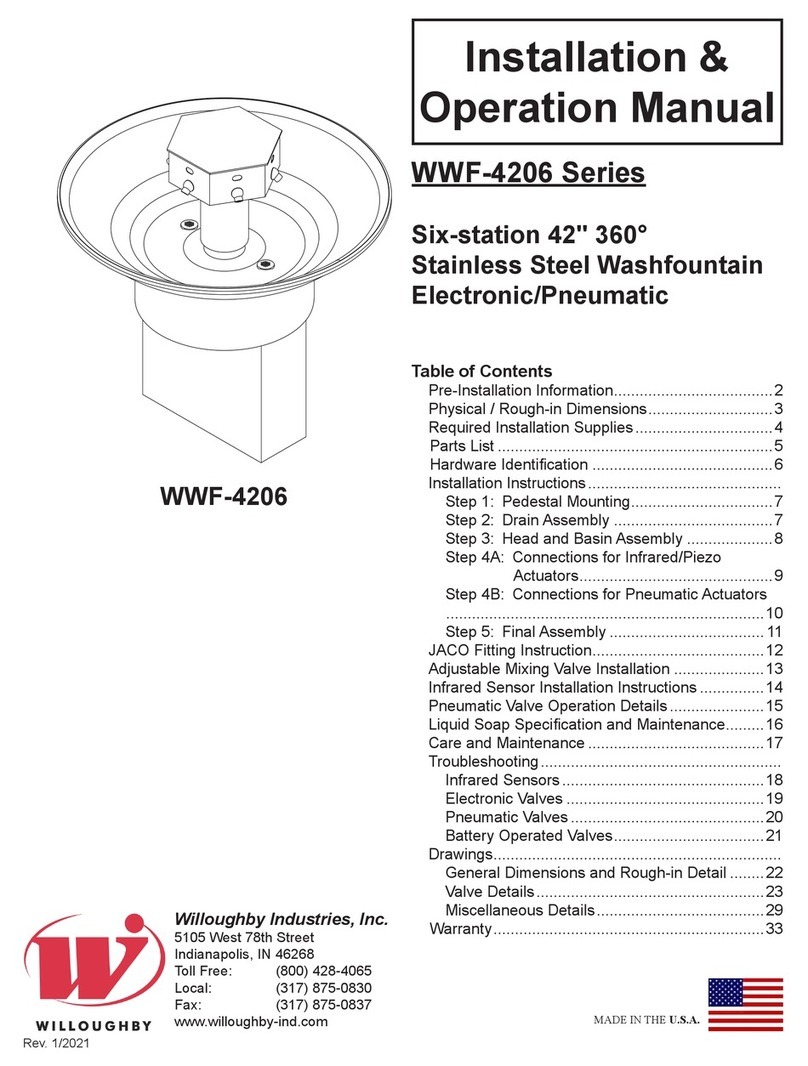
Willoughby Industries, Inc. WWF-4206-PSL-FT Series User manual

Willoughby Industries, Inc.
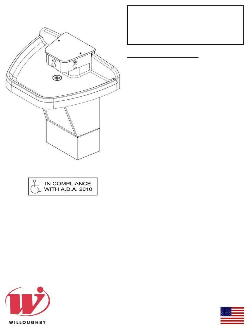
Willoughby Industries, Inc. WWF-4203 Series User manual
Willoughby Industries, Inc.
Willoughby Industries, Inc. AquaFount WAF-3300 Series User manual
Willoughby Industries, Inc.
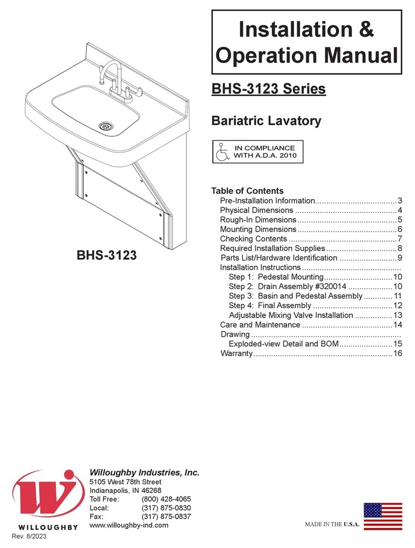
Willoughby Industries, Inc. BHS-3123 Series User manual
Willoughby Industries, Inc.
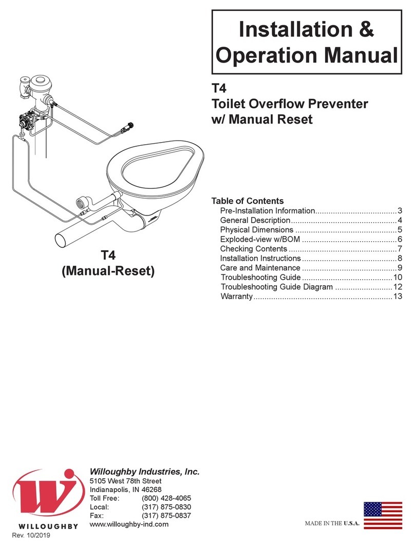
Willoughby Industries, Inc. T4 User manual

Willoughby Industries, Inc.
Willoughby Industries, Inc. WWF-5403 Series User manual
Popular Plumbing Product manuals by other brands

Moen
Moen SANI-STREAM 8797 manual

Grohe
Grohe Allure Brilliant 19 784 manual

Cistermiser
Cistermiser Easyflush EVO 1.5 manual

Kohler
Kohler Triton Rite-Temp K-T6910-2A installation guide

BEMIS
BEMIS FNOTAB100 Installation instruction

Hans Grohe
Hans Grohe ShowerTablet Select 700 13184000 Instructions for use/assembly instructions

Akw
Akw Stone Wash Basin Installation instructions manual

Enlighten Sauna
Enlighten Sauna Rustic-4 user manual

Moen
Moen ShowHouse S244 Series quick start guide

Sanela
Sanela SLWN 08 Mounting instructions

Franke
Franke 7612982239618 operating instructions

Heritage Bathrooms
Heritage Bathrooms Granley Deco PGDW02 Fitting Instructions & Contents List

Tres
Tres TOUCH-TRES 1.61.445 instructions

STIEBEL ELTRON
STIEBEL ELTRON WS-1 Operation and installation

Miomare
Miomare HG00383A manual

BELLOSTA
BELLOSTA revivre 6521/CR1 quick start guide

American Standard
American Standard Heritage Amarilis 7298.229 parts list

BorMann
BorMann Elite BTW5024 quick start guide


