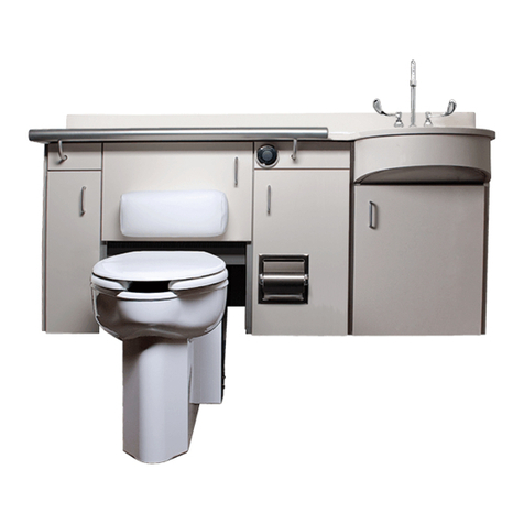
Willoughby WH-2400 Series User manual

INSTALLATION AND
OPERATION MANUAL
PAGE 1
© Rev. 2/2017
1.800.428.4065 TOLL FREE
| www.willoughby-ind.com
MODELS:
WH-2400 Series
Patient Care Units
TABLE OF CONTENTS
PRE-INSTALLATION INFORMATION ....................... 3
PHYSICAL DIMENSIONS .......................................... 4
ROUGH-IN DIMENSIONS ........................................ 5
CHECKING CONTENTS ............................................ 6
INSTALLATION INSTRUCTIONS .................................
Step 1: Unpacking the Patient Care Unit ......... 8
Step 2: Install the Anchors and Backing ........... 8
Step 3: Install the Vacuum Breaker .................... 9
Step 4: Install the WH-2400 Cabinet ............... 9
Step 5: Install the Toilet and
Waste Connections ...............................10
Step 6: Install the Solid Surface Lavatory
Top to the Cabinet ...............................10
Step 7: Install Faucet and Connect
Water Supply .......................................11
Step 8: Completing Installation ........................11
CARE AND MAINTENANCE ...................................12
DETAIL DRAWINGS ......................................................
Stationary PCU Toilet - Wall Waste Outlet
H1490-0078 ..................................................13
Stationary PCU Toilet - Floor Waste Outlet
H1490-0079 ..................................................14
WARRANTY ..............................................................15
WILLOUGHBY
HEALTHCARE
PATIENT CARE UNITS

WH-2400 SERIES
PATIENT CARE UNITS INSTALLATION & OPERATION MANUAL
PAGE 2 © Rev. 2/2017
1.800.428.4065 TOLL FREE
| www.willoughby-ind.com
(PAGE LEFT INTENTIONALLY BLANK)

WH-2400 SERIES
PATIENT CARE UNITS INSTALLATION & OPERATION MANUAL
PAGE 3
© Rev. 2/2017
1.800.428.4065 TOLL FREE
| www.willoughby-ind.com
When installing the Willoughby Industries’ WH-2400 Series Patient Care Units:
Before Step 1 of the Installation Instructions, ensure that rough-ins are in the
correct location.
It is essential that the water supply lines be thoroughly ushed prior to making
nal connection to the hot and cold water supply lines. These lines must be ushed
suf ciently to remove the small particles of debris that are inherent with new con-
struction projects.
If this debris is not removed, the valving in these units will be damaged. Do not
attempt to remove the aerators to ush debris out of the lavatory. The damage can
only be xed by replacing the valves. Damage to valves caused by debris will not
be covered by the manufacturer’s warranty.
INSTALLATION NOTICE!
CHECK ROUGH-IN LOCATIONS PRIOR TO INSTALLATION
FLUSH LINES THOROUGHLY PRIOR TO HOOK-UP
PRE-INSTALLATION INFORMATION
INSTALLATION NOTICE!
CHECK ROUGH-IN LOCATIONS PRIOR TO INSTALLATION
FLUSH LINES THOROUGHLY PRIOR TO HOOK-UP

WH-2400 SERIES
PATIENT CARE UNITS INSTALLATION & OPERATION MANUAL
PAGE 4 © Rev. 2/2017
1.800.428.4065 TOLL FREE
| www.willoughby-ind.com
PHYSICAL DIMENSIONS- WH-2400 SERIES

WH-2400 SERIES
PATIENT CARE UNITS INSTALLATION & OPERATION MANUAL
PAGE 5
© Rev. 2/2017
1.800.428.4065 TOLL FREE
| www.willoughby-ind.com
ROUGH-IN DIMENSIONS- WH-2400 SERIES
WH-2400 FLOOR ROUGH-IN TEMPLATE
WH-2400 BACK-WALL ROUGH-IN TEMPLATE

WH-2400 SERIES
PATIENT CARE UNITS INSTALLATION & OPERATION MANUAL
PAGE 6 © Rev. 2/2017
1.800.428.4065 TOLL FREE
| www.willoughby-ind.com
CHECK CONTENTS
• Separate all parts from packaging and make sure all parts are accounted for before
discarding any packaging material. If any parts are missing, do not attempt to install
WH-2400 Series Patient Care Unit until you obtain the missing parts.
NOTE: Before beginning installation, all supply, drain and waste piping for the
WH-2400 Series must be completed according to speci ed rough-ins. If you have not
received rough-in details, please contact Willoughby Industries, Inc. (800) 428-4065
IMPORTANT: These installation instructions
cover all of the Willoughby Industries Inc.
WH-2400 Series Patient Care Units. Simply
omit the steps which do not apply to the
model you are installing.
IMPORTANT: Flush all the water supply
lines before making connections.

WH-2400 SERIES
PATIENT CARE UNITS INSTALLATION & OPERATION MANUAL
PAGE 7
© Rev. 2/2017
1.800.428.4065 TOLL FREE
| www.willoughby-ind.com
□ Hardware for waste outlet connections
□ Gasket for waste outlet connection
□ Shims (for toilet or cabinet installation if necessary)
□ Supply piping to toilet, faucet, foot valve, vacuum breaker, bedpan washer (AS NEEDED)
□ Waste outlet piping to toilet
□ P-trap and drain piping
□ Silicone caulk
□ Proper mounting hardware
WARNING: Willoughby Industries does not assume any
responsibility for personal injury or damage to equipment due
to an improperly installed WH-2400 Series Patient Care Unit.
REQUIRED INSTALLATION SUPPLIES

WH-2400 SERIES
PATIENT CARE UNITS INSTALLATION & OPERATION MANUAL
PAGE 8 © Rev. 2/2017
1.800.428.4065 TOLL FREE
| www.willoughby-ind.com
INSTALLATION INSTRUCTIONS
Step 1: Unpacking the Patient Care Unit
1.) Remove the packaging around the unit.
2.) Locate wall and fl oor mounting templates (skid will be marked) and set aside.
(DO NOT DISCARD)
NOTE: Templates are not to be installed as part of the cabinet. They are only used to
specifi y rough-in measurements.
Step 2: Install the Anchors and Backing
1.) Select the location where the WH-2400 is to be installed. Using the supplied templates, mark
all mounting and rough-in locations.
2.) Remove the templates.
3.) Install appropriate fl oor anchors to mount the toilet Z-clip securely to the fl oor (hardware
supplied by installer).
4.) For wall outlet toilets, install the appropriate fl oor anchors in the specifi ed locations.
NOTE: If the fl oor concrete is lightweight or less than 4” thick, through-bolting to steel
angles under the fl oor is recommended (hardware supplied by installer).
5.) Install adequate backing for mounting the cabinet securely to the wall.
NOTE: Adequate backing and mounting hardware by others.
6.) Install (3) Z-clips to the wall backing. Use template to determine locations.

WH-2400 SERIES
PATIENT CARE UNITS INSTALLATION & OPERATION MANUAL
PAGE 9
© Rev. 2/2017
1.800.428.4065 TOLL FREE
| www.willoughby-ind.com
INSTALLATION INSTRUCTIONS (CONT.)
Step 4: Install WH-2400 Series Cabinet
1.) With assistance, lift the cabinet and align the Z-clip mounting holes in the back of the
cabinet with the Z-clips mounted on the wall in Step 2. When aligned, carefully lower cabinet
onto the Z-clips.
2.) Once the cabinet is level, secure cabinet to wall through horizontal mounting slots with
proper hardware.
3.) Level and secure cabinet by installing lower mounting brackets with proper hardware
NOTE: Mounting hardware by others.
Step 3: Install the Vacuum Breaker for the WH-2400 Series
Patient Care Unit w/ Bedpan Washer
1.) Install the supplied vacuum breaker to the wall per local code.
NOTE: The vacuum breaker must be mounted on the wall a minimum of 6’ from the
fl oor along the centerline of the valve.
2.) Connect the wall piping to the inlet and outlet on the vacuum breaker.
3.) Before installing the cabinet, connect the vacuum breaker outlet to the bedpan washer inlet.
NOTE: All other plumbing connections are made after the cabinet is installed.

WH-2400 SERIES
PATIENT CARE UNITS INSTALLATION & OPERATION MANUAL
PAGE 10 © Rev. 2/2017
1.800.428.4065 TOLL FREE
| www.willoughby-ind.com
Step 6: Install the Solid Surface Lavatory Top to the Cabinet
1.) Install the drain assembly inside the lavatory.
2.) Apply a bead of silicone caulk around the outer top edge of the cabinet and between the
lavatory top and the wall.
3.) Set the lavatory top in place on the cabinet making sure the back is fl ush with the wall.
Clean up excess caulk around the countertop edge.
Step 5: Install the Toilet and Waste Connections
1.) Slide toilet into position over the fl oor Z-clip installed in Step 2.
2.) Connect the toilet to the fl oor/wall waste outlet with appropriate gasket. Be sure to square the
toilet assembly to the back wall.
3.) Level and support the toilet solidly at the four corners using shims, if needed
(shims supplied by installer).
4.) Secure the toilet in place with appropriate hardware.
NOTE: If the waste outlet is through the back, use a no-hub type connector
(available as an option).
5.) On WH-2400 models with a back waste connection, tighten the connector clamps at this time.
INSTALLATION INSTRUCTIONS (CONT.)

WH-2400 SERIES
PATIENT CARE UNITS INSTALLATION & OPERATION MANUAL
PAGE 11
© Rev. 2/2017
1.800.428.4065 TOLL FREE
| www.willoughby-ind.com
INSTALLATION INSTRUCTIONS (CONT.)
Step 7: Install Faucet and Connect Water Supply
NOTE: Please refer to faucet manufacturer’s recommended installation instructions.
Step 8: Completing Installation
1.) Connect the fl ush valve outlet to the water closet.
NOTE: Tighten all fl ush valve connections.
2.) Install the P-trap (supplied by installer) to the sink drain, and then connect the P-trap to the
drain pipe (piping supplied by installer).
3.) After all toilet, faucet, and bedpan washer connections are checked for leaks, activate several
times to purge air from the supply lines.
4.) Position Folding Toilet Cover and/or Toilet Shroud Assembly and secure to the toilet with
attachment screws.
5.) Align and secure the folding cover recess cabinet door onto the WH-2400 cabinet.
6.) Close all access doors when fi nished.

WH-2400 SERIES
PATIENT CARE UNITS INSTALLATION & OPERATION MANUAL
PAGE 12 © Rev. 2/2017
1.800.428.4065 TOLL FREE
| www.willoughby-ind.com
CARE AND MAINTENANCE

WH-2400 SERIES
PATIENT CARE UNITS INSTALLATION & OPERATION MANUAL
PAGE 13
© Rev. 2/2017
1.800.428.4065 TOLL FREE
| www.willoughby-ind.com
DRAWING: STATIONARY PCU TOILET - WALL WASTE OUTLET
7-1/2"
23-5/8"
3/5/15
A1 OF 1
H1490-0078
1:8
N/A
PART #:
PETWS-1490-FM-BS-HC-1.6-DC
EXCEPT AS 3 PLCS:
ANGLE: 3/5/15
TOILET ASSEMBLY-PATIENT CARE- 17" TALL
SHEET:REV.:
ORIG.:REVISION:
SCALE: REF.:
MAT'L:
TITLE / DESC.:
NOTED
SIZE: EEF
2 PLCS:
TOLERANCES A
Indianapolis, Indiana
1
FRACTIONS: EEF
0.03
0.015
1/32"
Willoughby Industries, Inc.
STANDARD
BACK VIEW
STANDARD STAIONARY TOILET
FOR PATIENT CARE UNIT W/
WALL WASTE OUTLET
ATTACH TO FLOOR W/
Z-CLIP (PROVIDED), ANCHORING
HARDWARE BY OTHERS
1" WIDE STRUT WELDED
TO BOTTOM OF TOILET
SKIRT FOR Z-CLIP
OF Z-CLIP SLOTS
15-5/8" TO C
L
1"
C
L
16-1/8"
SLOT C
L TO SLOT
17"
FLUSH INLET
1-1/2" M.I.P 2-1/2' O.D.
WASTE EXTENSION
16"
7-1/2"
4-1/2" 4-1/2"
16"
(2) 1/2" SEAT
MOUNTING HOLES
WHITE
11-7/8" 5-7/16"
1-1/8"
4-3/4"
WILLOUGHBY

WH-2400 SERIES
PATIENT CARE UNITS INSTALLATION & OPERATION MANUAL
PAGE 14 © Rev. 2/2017
1.800.428.4065 TOLL FREE
| www.willoughby-ind.com
DRAWING: STATIONARY PCU TOILET - FLOOR WASTE OUTLET
23-5/8"
17"
1-1/2" M.I.P.
FLUSH INLET
(4) 3/4"
MOUNT HOLES
7-1/2"
16"
4-1/2" 4-1/2"
16"
17"
(2) 1/2" SEAT MOUNTING HOLES
(2) 3/8" FLOOR ANCHOR HOLES
FASTENERS BY OTHERS
6"
1-1/8"
2-7/8"
11-7/8"
5-7/16"
8"
1
Indianapolis, Indiana
EEF
EEF 3/5/15
3/5/15
A1 OF 1
H1490-0079
1:8
N/A
2 PLCS: SIZE:
TOILET ASSEMBLY-PATIENT CARE- 17" TALL
SHEET:REV.:
ORIG.:REVISION:
SCALE: REF.:
MAT'L:
PART #:
A
ANGLE:
PETF-1490-FM-BS-HC-1.6-DC
TITLE / DESC.:
FRACTIONS:
3 PLCS:
EXCEPT AS
TOLERANCES
NOTED
0.03
0.015
1/32"
Willoughby Industries, Inc.
STANDARD
FLOORWASTE OUTLET
WHITE
STANDARD STATIONARY TOILET
FOR PATIENT CARE UNITS W/
1.6 GPF
1" WIDE STRUT WELDED
TO BOTTOM OF TOILET
SKIRT FOR Z-CLIP
BY OTHERS
ANCHORING HARDWARE
Z-CLIP (PROVIDED)
ATTACH TO FLOOR W/
2-1/2" O.D. FLOOR WASTE
CONNECTION W/ 7-1/2"
GASKET FLANGE
OF Z-CLIP SLOTS
15-5/8" TO C
L
1" OFFSET
WILLOUGHBY

WH-2400 SERIES
PATIENT CARE UNITS INSTALLATION & OPERATION MANUAL
PAGE 15
© Rev. 2/2017
1.800.428.4065 TOLL FREE
| www.willoughby-ind.com
WARRANTY
Table of contents
Other Willoughby Indoor Furnishing manuals
Popular Indoor Furnishing manuals by other brands

King Living
King Living King Boulevard Assembly instructions

VIPACK
VIPACK ERIK ERNA1214 Assembly instructions

Living Spaces
Living Spaces DE-GCL-FUO-4824XL owner's manual

Forte
Forte SFNS721R Assembling Instruction

Furniture of America
Furniture of America CM7760GM Assembly instructions

Aulum
Aulum 703-147-1052 Assembly instructions