WillowWood LimbLogic Series User manual

1
LimbLogic®
Prosthetist
Instructions
WHAT'S IN THE BOX
LimbLogic Pump*
Battery Charger*
Fob
Fob Battery (quantity=2)
Fob Key Ring
Diagnostic Disc or Sheet and Sealing Gasket (packaged together)
Exhaust Port Drain Tube
Replacement Exhaust Hose and Muffler*
Patient Instructions
Prosthetist Instructions
Quick-Start Guide
*Quantity = 2 for bilateral kit
This document provides instruction for the prosthetist in the
installation and use of the system. A separate document,
LimbLogic Patient Instructions, is included with each system
and should be provided to the patient upon delivery of a
prosthesis containing the LimbLogic.
The Vacuum Pump and fob included in this package are
electronically keyed together. They can be used only with
each other unless they are re-keyed with a LImbLogic
Communicator.

2
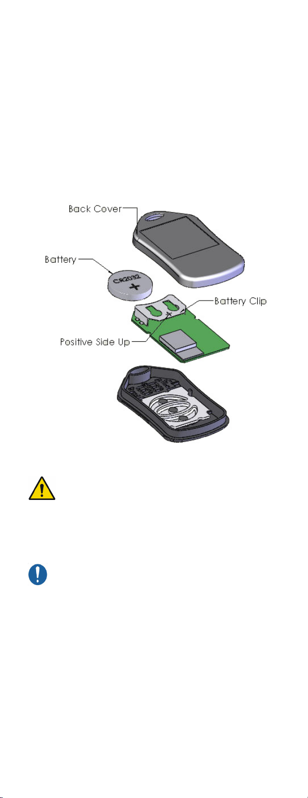
There are no field-serviceable parts inside the
Vacuum Pump. Opening the Vacuum Pump or
charger may result in injury or death and will
void the warranty.
Unauthorized changes or modifications to the
LimbLogic pump or accessories may; impair their
function resulting in injury or death, will void the
warranty, and may prevent their compliance with
relevant standards.
This pump is only designed to move air; use of
Vaseline®or similar lubricating creams inside the
socket will clog the pump. Do not allow foreign
substances to be pulled through the Vacuum Pump.
This may impair function of your vacuum system.
Do not allow acetone to contact the Vacuum Pump or fob.
All LimbLogic components have passed safety
testing for use as medical devices. Radio enabled
devices comply with United States and international
guidelines for low power transceivers. If LimbLogic
components will be used around safety critical
devices such as pacemakers or defibrillators, consult
the manufacturer for appropriate usage instructions.
Failure to do so may result in injury or death. Consult
the section on Regulatory Information for more
information on safety and compliance.
LimbLogic is designed for use by a single patient only.
Use on more than one patient may result in cross-
contamination potentially causing a serious infection.
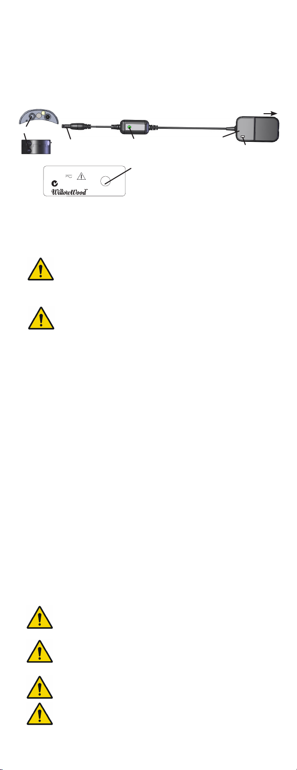
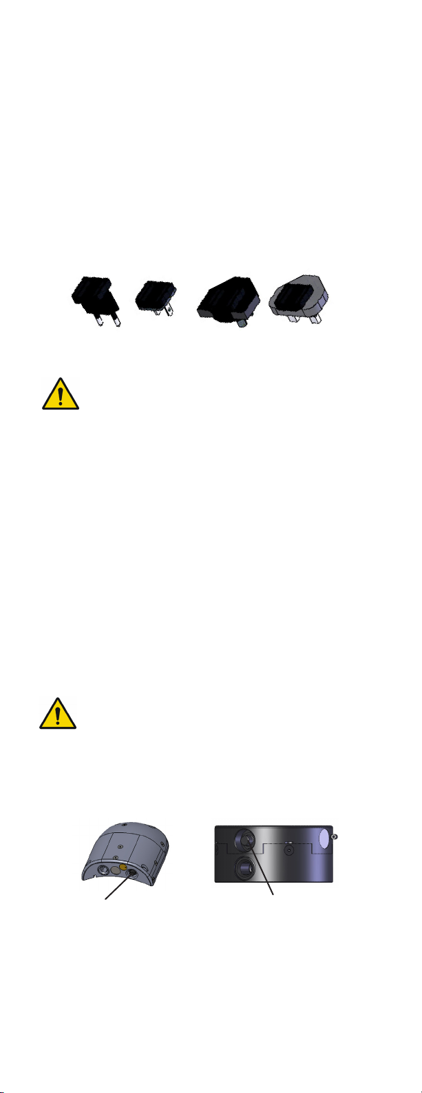
Charge the Vacuum Pump in a well-ventilated area
at a temperature between 5 °C (41 °F) and 33 °C
(90 °F). Failure to do so may result in prolonged or
incomplete charging of the Vacuum Pump and
may damage the Vacuum Pump.
A Vacuum Pump enclosed by a cosmetic cover will
retain heat, but in most cases should charge
normally at temperatures below 27 °C (80 °F). The
battery may not fully charge at higher temperatures.
Use of the LimbLogic at temperatures above 41 °C
(106 °F) may heat the surface of the product to
unsafe temperatures which could cause burns with
extended contact. Use care when operating the
LimbLogic at high temperatures.
LimbLogic has been constructed using polymer
materials to create a durable, lightweight, water-
tight, and radio-transparent design. These materials
have all been certified to an inflammability rating of
at least HB per UL 94. However, polymers can melt
or burn if exposed to high temperatures or flame.
Do not expose your LimbLogic product to these
conditions. Doing so may result in ignition resulting
in injury or death.
LimbLogic pumps cannot compensate for failures in
the associated prosthetic socket or sealing system.
Only use LimbLogic pumps with commercially proven
socket and sealing systems. Use with other sealing
systems may result in loss of suspension resulting in
injury or death.
Electrical equipment can interact. Do not operate
the fob, charger, or either LimbLogic pump design
while they are stacked upon, or in close proximity
to, other electrical equipment without monitoring
performance. Doing so may result in equipment
malfunction or failure.

3
FCC NOTICE
Note:
This device complies with part 15 of the FCC Rules. Operation
is subject to the following two conditions: (1) This device may
not cause harmful interference, and (2) this device must accept
any interference received, including interference that may cause
undesired operation.
Changes or modifications not approved by The Ohio Willow Wood
Company may degrade performance, possibly leading to injury or
death and will void the user’s authority to operate this equipment.
IC Notice
Note:
This device complies with Industry Canada RSS standards
applicable to radio devices. Operation is subject to the following
two conditions: (1) this device may not cause interference, and (2)
the user of the device must accept any interference, including
interference that may cause undesired operation.
Remarque:
Le présent appareil est conforme aux CNR d‘Industrie Canada
applicables aux appareils radio . L‘exploitation est autorisée aux
deux conditions suivantes: (1) l‘appareil ne doit pas produire
de brouillage, et (2) l‘utilisateur de l‘appareil doit accepter tout
brouillage radioélectrique subi, même si le brouillage est
susceptible d‘en compromettre le fonctionnement.Cuppl. Edius
maxim in sultilin hendio hoc revid dii tem anterfectam ur atiam
The Side Mount LimbLogic Vacuum Pump has been
designed and tested for mounting on transfemoral
sockets. Use in other configurations may result in
tripping or other hazards.

4
TABLE OF CONTENTS
Page
Installing the Fob Battery ...............................................................................5
Quick-Start Guide ...............................................................................................6
Fob Guide ...............................................................................................................6
Keys to Successful Use.....................................................................................7
Introduction ...........................................................................................................8
Vacuum System Function...............................................................................8
Charging the Vacuum Pump Battery........................................................9
Charging the Vacuum Pump Battery Outside the U.S. ..................10
Charging the Vacuum Pump Battery in a Vehicle.............................10
Turning On the Vacuum Pump...................................................................10
Turning O the Vacuum Pump.....................................................................11
Resetting the Vacuum Pump ........................................................................11
Turning On the Fob............................................................................................11
Changing Vacuum Set Point........................................................................ 12
Changing Pump State..................................................................................... 12
Bilateral Indicators............................................................................................ 13
Changing the Prosthetist Settings............................................................ 14
Detecting a Leak ............................................................................................... 15
Vacuum Pump Battery Status .................................................................... 15
Exposure to Water............................................................................................ 15
Vacuum Plate/Pyramid .................................................................................. 16
Exhaust Tube Muer Cleaning....................................................................17
Potential Home Challenges...........................................................................17
Troubleshooting Guide................................................................................... 18
Diagnostic Disc or Sheet.............................................................................. 22
Service Life.......................................................................................................... 23
Warranty............................................................................................................... 23
Regulatory Information................................................................................. 24

5
Overview
INSTALLING THE FOB BATTERY
The fob uses a commercially available CR2032 coin cell battery.
The battery that is shipped with the system must be installed prior
to using the fob.
The battery will normally have to be replaced every 3 months
depending upon how much the fob is used.
The fob case can be pried open using a small flat blade screw-
driver, then snapped back together starting at the battery end
and working back toward the opposite end.
The fob battery could cause serious injury or death
including choking. Keep coin cell type batteries away
from children.
After the battery is replaced, the system does a quick
check by illuminating all the LED indicators. If all of the
LEDs do not illuminate, then either the battery or the
LEDs are not working, or the battery has been installed
upside-down.

6
QUICK-START GUIDE
2. Turn on the fob.
6. Turn o the Vacuum Pump.
1. Turn on the Vacuum Pump.
Press one time.
Pump will beep once.
Wait 10 seconds.
Press one time.
Pump will beep either two
or four times:
• Two beeps if the pump
was in Standard Mode
• Four beeps if the pump
was in Adaptive Mode*
Overview
FOB GUIDE
Current
Vacuum
Level
Bilateral Indicators
Standby/Active
Indicator
(White)
Leak
Indicator
(Red)
Up
Enter
Down
Vacuum Pump Battery Indicator
50-100%
30-50%
20-30%
< 20%
Press and hold center button until the yellow
digits flash in a “chasing” pattern and then
display the current vacuum level.
The pump is now Active and will operate
until the preselected vacuum level has been
reached.
3. To enter Standby State:
To resume vacuum regulation:
Press for approximately 2 seconds.
The chasing pattern will be displayed,
then the white Standby Indicator will light.
Press for approximately 2 seconds.
The chasing pattern will be displayed
as the pump returns to Active State.
*All LimbLogic pumps ship from the factory configured for
Standard Mode. Refer to the LimbLogic Communicator
User’s Guide for information on additional Modes and features
available through use of the Communicator.

7
Overview
KEYS TO SUCCESSFUL USE
1. Fabricate a non-porous Total Surface Weight Bearing socket:
• For a transtibial socket, use either a LimbLogic 4-Hole
Attachment Plate or LimbLogic Drop-In Adapter. Follow
the fabrication instructions provided with the adapter.
• For a transfemoral socket, follow the fabrication
instructions provided with the WillowWood One System
- Socket Fabrication Instructions booklet.
Prior to delivering the prosthesis, you may want to use the
Diagnostic Disc or Sheet to confirm that there are no leaks
in the system (refer to page 22).
2. Fully charge the Vacuum Pump. (Refer to “Charging the
Vacuum Pump Battery” on page 9.)
3. Properly secure the fully charged Vacuum Pump to the
prosthesis:
• Press a sealing gasket into the inlet of the pump.
Drawing No.
NA
TJB
XX/XX/XX
0
Part Number
T.J. Braden
DRAWING NUMBER
MAT'L
SCALE
CHK'D BY
DRAWN BY
±0° 30' DEG.
±1/64 FRAC.
±.0005
±.005
±.01
±.04
.xxxx
.xxx
.xx
.x
TOLERANCES, UNLESS OTHERWISE NOTED
PART FINISH
PART NAME
ECO#
BY
DATE
REV
REVISIONS
THE OHIO WILLOW WOOD COMPANY, INC.
Material
"CONFIDENTIAL"
Black Ring Socket.SLDDRW(Default)
Part File: F:\Cheryl Limblogic\Assem1.SLDPRT
PART NUMBER
SHEET-X OF X
Part Finish
MACHINE
Black Ring Socket
THE INFORMATION CONTAINED IN THIS DRAWING IS THE SOLE PROPERTY OF
OHIO WILLOW WOOD COMPANY. ANY REPRODUCTION IN PART OR WHOLE WITHOUT
THE WRITTEN PERMISSION OF OHIO WILLOW WOOD COMPANY IS PROHIBITED.
Be sure to fully seat the gasket onto the inlet before
attaching the pump to the socket. Failure to properly
seat the gasket may result in leaks.
Note: when using the Drop-In Adapter, two gaskets are
required. After seating the first gasket onto the pump,
stack the second gasket on top of the first gasket
before attaching the pump to the socket.
You should be able to
turn the pump upside
down as shown without
the gasket falling o.
If the gasket falls o,
it was not properly
seated into the recess.
THE INFORMATION CONTAINED IN THIS DRAWING IS THE SOLE PROPERTY OF
OHIO WILLOW WOOD COMPANY. ANY REPRODUCTION IN PART OR WHOLE WITHOUT
THE WRITTEN PERMISSION OF OHIO WILLOW WOOD COMPANY IS PROHIBITED.
Assem1
MACHINE
Part Finish
SHEET-X OF X
PART NUMBER
Part File: F:\Cheryl Limblogic\Assem1.SLDPRT
Assem1.SLDDRW(Default)
"CONFIDENTIAL"
Material
THE OHIO WILLOW WOOD COMPANY, INC.
REVISIONS
REV
DATE
BY
ECO#
PART NAME
PART FINISH
TOLERANCES, UNLESS OTHERWISE NOTED
.x
.xx
.xxx
.xxxx
±.04
±.01
±.005
±.0005
±1/64 FRAC.
±0° 30' DEG.
DRAWN BY
CHK'D BY
SCALE
MAT'L
DRAWING NUMBER
T.J Braden
Part Number
0
XX/XX/XX
TJB
NA
Drawing No.
Correct Incorrect
(not seated properly)
THE INFORMATION CONTAINED IN THIS DRAWING IS THE SOLE PROPERTY OF
OHIO WILLOW WOOD COMPANY. ANY REPRODUCTION IN PART OR WHOLE WITHOUT
THE WRITTEN PERMISSION OF OHIO WILLOW WOOD COMPANY IS PROHIBITED.
Assem1
MACHINE
Part Finish
SHEET-X OF X
PART NUMBER
Part File: F:\Cheryl Limblogic\Assem1.SLDPRT
Assem1.SLDDRW(Default)
"CONFIDENTIAL"
Material
THE OHIO WILLOW WOOD COMPANY, INC.
REVISIONS
REV
DATE
BY
ECO#
PART NAME
PART FINISH
TOLERANCES, UNLESS OTHERWISE NOTED
.x
.xx
.xxx
.xxxx
±.04
±.01
±.005
±.0005
±1/64 FRAC.
±0° 30' DEG.
DRAWN BY
CHK'D BY
SCALE
MAT'L
DRAWING NUMBER
T.J Braden
Part Number
0
XX/XX/XX
TJB
NA
Drawing No.
gasket
• For a Distal Mount pump: attach the pump and sealing
gasket(s) to the socket, Vacuum Plate (LLV-01043), or
Vacuum Pyramid (LLV-01044) with M6 flathead screws.
For a definitive prosthesis, apply Loctite 242 Removable
Threadlocker (or equivalent) to the screws, and tighten
the screws to 9 ft-lbs (12 Nm).
• For a Side Mount pump: attach the pump and sealing
gasket to the Side Mount Lamination Plate on the socket
using the M4x10 socket head cap screws. For a definitive
prosthesis, apply Loctite 242 Removable Threadlocker
(or equivalent) to the screws, and tighten the screws to
22 in-lbs (2.5 Nm).

8
INTRODUCTION
LimbLogic is a remote-controlled vacuum
suspension system that is completely
integrated into the prosthesis without the
annoyances of tubes in the socket. The
Side Mount pump mounts on the side
of the patient’s socket, while the Distal
Mount pump mounts inline on the pa-
tient’s socket. LimbLogic operates quietly
and features “Set and Forget” monitoring,
which means that the system monitors
the level ofvacuum in the socket so as to
maintain a secure and comfortable fit.
The miniaturized LimbLogic fob provides the user with control
and status information for the LimbLogic System. The fob uses
lights or digits to display the Vacuum Pump’s current usage
mode, the battery level, the current vacuum level, and leak
indicators. The vacuum level and range can be changed using
the buttons located on the fob.
VACUUM SYSTEM FUNCTION
The system monitors the vacuum level and draws more vacuum
as needed to maintain the level within a designated Vacuum
Range. The desired vacuum level, also known as the Vacuum
Set Point, is the upper limit of this range, and can be adjusted
by the patient; however, the Vacuum Set Point is limited by the
User Maximum setting.
The system is shipped with the Vacuum Range set at 4 and
the User Maximum set at 20, but if those settings are not
suitable for your patient, you may adjust them as desired.
The User Maximum cannot be set higher than the system
maximum of 20.
The optimum vacuum setting is dierent for each amputee.
Keep in mind that a higher vacuum level is not always better.
Higher vacuum levels require that the Vacuum Pump use
more power and will therefore discharge the battery faster.
PATIENT BRIEFING
The LimbLogic pump has been designed and tested for durability and
usage in common environments. While unlikely to result in unsafe
performance, there are extreme conditions which may affect the
LimbLogic’s function.
Be sure to train patients:
• Not to use their LimbLogic in corrosive environments, such as
salt water.
• Not to use the LimbLogic outside of its specified range of
environmental conditions. (Refer to “Performance
Characteristics” on page 31.)
• How to start, stop, and reset their pump in the event of
malfunctions caused by unusual conditions such as Electrostatic
Discharge, such as experienced after walking across carpet;
or extreme electric fields, such as those caused by power
transformers, or large electric equipment.
• How to release the vacuum in their socket.
• To obtain medical attention in the even of an open wound on
their residual limb.
• How to contact you, as WillowWood’s representative to this
patient, in the event that they have questions about the
configuration, use, or maintenance of their LimbLogic.
Overview

9
1. The Vacuum Pump must be charged in a well-ventilated area
between the temperatures of 5 °C (41 °F) and 32 °C (90 °F).
Charging outside of this range may result in prolonged or
incomplete charging and may damage your Vacuum Pump.
Only charge the Vacuum Pump in a well ventilated
area at a temperature between 5 °C (41°F) and 32°C
(90°F). Charging outside of these conditions may
damage the Vacuum Pump.
A Vacuum Pump enclosed by a cosmetic cover will
retain heat, but in most cases should charge normally
at temperatures below 27°C (80°F). The battery may
not fully charge at higher temperatures.
2. Insert the charging plug all the way into the charging port.
3. Plug the Charger into a power outlet. The Adapter LED will
light. If the Node LED does not light, make sure you have
inserted the charging plug all the way into the port.
If the Node LED is red, reset the Charger by unplugging it
from the wall and plugging it back in.
While charging is in progress, the Node LED will be solid. The
battery indicator on the fob will flash alternately between red
and green.
4. When charging is complete, the Node LED will flash.
Disconnect the Charger from the Vacuum Pump and from
the power outlet.
When you are ready for the pump to begin regulating the
vacuum, either turn on the fob (refer to page 11) or press the
on/o button on the Vacuum Pump. The pump will operate
until the preselected vacuum level is reached.
Note: Your pump can be used while charging. If the pump has
just been unplugged from the Charger, it will be in Standby State
(refer to page 11). To resume vacuum regulation, press the on/o
button one time for Active State. Press again to turn the pump o.
Walking while charging your pump may cause you to trip
and fall. Do NOT walk while your LimbLogic is plugged into
the charger.
Use ONLY a WillowWood Charger. Use of any other charger
may result in damage to the Vacuum Pump or the charger
or both and may negatively aect EMC performance and/
or compliance and may result in serious injury or death.
The charger may pose both a strangulation and/or
electrocution hazard and should not be handled by children.
Do not use the Charger near water. The Charger is
not waterproof. Use of the charger near water may
result in serious injury or death.
Overview
CHARGING THE VACUUM PUMP BATTERY
The Vacuum Pump should be charged before it is used for the
first time, at the end of each day of use, and when the Battery
Indicator on the fob is red.
Node LED
(indicates Charger function)
RED = fault
SOLID = charging
FLASHING = charged
Flashing:
Charged
13.8 0V
LLV-21011
solid:
Charging
2012 PN-1988-H
ABN: 22582837497
charging port
Charger
Vacuum Pump
To AC outlet
charging plug Adapter LED
(indicates that
AC outlet is
providing power
to Charger)
Node LED AC Adapter

10
TURNING ON THE VACUUM PUMP
CHARGING THE VACUUM PUMP BATTERY IN A VEHICLE
To use a vehicle’s power to charge the Vacuum Pump, you must
purchase a Power Inverter rated at 75 Watts or less to convert the
vehicle’s 12V DC power to 120V AC. An example of an acceptable
Power Inverter is the Digital Concepts™ 75 Watt Portable Power
Inverter (available from general retailers).
1. Plug the Power Inverter into the vehicle’s 12V DC socket.
2. Connect the Charger to the Vacuum Pump.
3. Plug the Charger’s AC Adapter into the Power Inverter’s
three-pronged receptacle.
Do not operate the Charger above 41˚C (105˚F).
The battery may not fully charge at higher temperatures.
Press the on/o button on the Vacuum Pump one time. The
Vacuum Pump will beep once.
Before turning on the fob as described below, wait 10
seconds for the pump to activate.
Overview
on/o button on/o button
Your battery will power your LimbLogic pump for at least a
full 18 hour day of normal usage. It will do so for the life of the
product. (Refer to “Service Life” on page 23.) If it is unable to
do so, please refer to the troubleshooting section or contact
WillowWood.
CHARGING THE VACUUM PUMP BATTERY OUTSIDE THE
UNITED STATES
Chargers sold for use outside the U.S. come with a set of prong
adapters. These adapters allow you to use the Charger in many
countries.
Plugging a prong set into an outlet without the
Charger may expose you to dangerous voltages
potentially leading to injury or death. Always
plug the prong set into the Charger before plugging
the Charger or the prong set into an outlet.

11
Enter
Current
vacuum level
Overview
TURNING ON THE FOB
Make sure the pump has been on for at least 10 seconds.
Press and hold the Enter (center) button for approximately
2 seconds until the yellow digits flash in a circular “chasing”
pattern. The chasing pattern indicates the fob is attempting to
communicate with the pump.
When the fob connects to the pump, the current vacuum level
will be displayed in the center. A connected fob will shut o
after one minute of non-use.
If the pump is o or fails to connect to the fob, the chasing
pattern will end after 6 seconds, and all fob LEDs will turn o.
For bilateral systems, if the fob cannot establish communications
with the first pump, the fob will attempt to connect to the
second pump, using the same steps as above. If communication
cannot be established with either pump, the fob will shut down.
RESETTING THE VACUUM PUMP
It is possible for a large static discharge to interrupt normal
operation. Should this occur, press the on/o button on the
Vacuum Pump and hold for at least 12 seconds until the unit
beeps. Resetting the pump may also be required when the fob
displays certain error codes (refer to page 21).
TURNING OFF THE VACUUM PUMP
Press the on/o button on the Vacuum Pump and hold for
1 second. The pump will beep several times to indicate that it
has been turned o. Refer to the Quick-Start Guide (page 6) for
more information.
Note: if the pump has just been unplugged from the Charger, it
will be in Standby State (refer to page 12). To resume vacuum
regulation, press the on/o button one time for Active State.
Press again to turn the pump o.

12
CHANGING VACUUM SET POINT
Make sure the fob is on and displaying the current vacuum level
in the yellow digits.
Press the Up or Down button for 1 second until the yellow digits
flash to indicate that the Vacuum Set Point is being changed.
Adjust the Vacuum Set Point as follows:
• Press the Up or Down button repeatedly to adjust the
Vacuum Set Point by one number at a time.
or
• Press and hold the Up or Down button until the desired
Vacuum Set Point is displayed.
Press the Enter button to apply the changes. The “chasing”
pattern will be displayed while the setting is being applied. If the
Enter button is not pressed, the settings will not be applied, and
the fob will shut o due to inactivity in 60 seconds.
CHANGING PUMP STATE
Make sure the fob is on and displaying the current vacuum level.
When the pump is on, it has two available usage states:
Active: activates as needed to maintain the vacuum level
Standby: allows you to temporarily suspend
vacuum regulation
Press and hold the Enter button to toggle the vacuum pump
between these two states. The “chasing” pattern will be
displayed while the change is being applied.
The white Standby/Active indicator will illuminate as follows:
Not illuminated: Active
Illuminated: Standby
Enter
Current
vacuum level
Up
Down
Enter
Standby/Active
Indicator
Overview

13
Up
Bilateral
Indicators
Down
Leak
Indicator
Enter
If the pump detects a leak, the red Leak Indicator will illuminate,
the usage mode will change to Standby State, and the pump will
beep 10 times rapidly. The pump will repeat this every 30 seconds
for 6 minutes unless acknowledged by pressing the on/o button
on the pump.
To return to Active State,press and hold the Enter button.
BILATERAL INDICATORS
If a fob is configured to support bilateral Vacuum Pumps, one of
the two white indicators at the top of the fob will illuminate to
show which pump (left or right) is being controlled.
To switch the fob from controlling one pump to the other, press
and hold the Up and Down buttons together for approximately
1 second. The “chasing” pattern will be displayed, and the indicator
light will switch from one side to the other while communication
with the other pump is being established.
If communication is established, the displays and controls are
similar to those for a unilateral system.
If no communication can be established, the fob will return to
controlling the pump that it controlled prior to the attempted
switch.
Overview

14
CHANGING THE PROSTHETIST SETTINGS
The system is shipped with the User Maximum set at 20 and the
Vacuum Range set at 4. If these settings are not appropriate for
your patient, you may adjust them as follows:
Make sure the pump and fob are both turned on and are
communicating with each other. Quickly press the Enter button
on the fob three times to enable the Prosthetist Settings function.
The three presses must be within approximately two seconds
of each other.
The display will alternate between two quick
flashes of this symbol and the current value for
the User Maximum.
Press the Up or Down buttons to adjust the User Maximum.
The digits will flash to indicate that the User Maximum is being
changed.
• The user will not be able to increase the Vacuum Set Point
above the User Maximum.
• The User Maximum cannot be set higher than 20.
Press the Enter button to apply the new User Maximum setting
and advance to the next setting.
The display will alternate between two quick
flashes of this symbol and the current value for
the Vacuum Range.
Press the Up or Down buttons to adjust the Vacuum Range.
The digits will flash to indicate that the Vacuum Range is being
changed.
• The Vacuum Range is how much the current vacuum level can
fall below the Vacuum Set Point before the pump activates.
• The Vacuum Range cannot be set lower than 4.
Press the Enter button to apply the new Vacuum Range setting.
The “chasing” pattern will be displayed while the setting is
being applied. The fob will then return to displaying the current
vacuum level.
NOTE: Adjusting the User Maximum and Vacuum Range Settings
can aect the Vacuum Level setting. After changing either the
User Maximum or Vacuum Range settings, please check to
ensure the Vacuum Level is set to the desired level.
Overview

15
Leak
Indicator
Vacuum Pump
Battery Indicator
DETECTING A LEAK
If the Vacuum Pump detects a leak, the red Leak Indicator
will illuminate, and the system will enter Standby State.
At this time, the pump will make 10 short beeps. This will repeat
every 30 seconds for 6 minutes unless acknowledged by
pressing the on/o button on the pump.
If the Leak Indicator appears when the patient initially dons the
prosthesis, the patient should restart the pump.
If the Leak Indicator appears frequently while the patient is
walking, use the Diagnostic Disc or Sheet to determine the
source of the leak (refer to page 22).
To resume automatic vacuum regulation after a leak has been
detected, press the on/o button on the Vacuum Pump one
time or press the Enter button on the fob.
VACUUM PUMP BATTERY STATUS
The Battery Indicator flashes alternatively between red and green
when the Vacuum Pump battery is charging.
The level of charge is indicated as follows:
• Solid green: Vacuum Pump battery is between 50% and
100% charged.
• Flashing green: Vacuum Pump battery is between 30% and
50% charged.
• Solid red: Vacuum Pump battery is between 20% and 30%
charged.
• Flashing red: Vacuum Pump battery is less than 20% charged.
The battery should be charged when possible. The pump will
shut down when the battery level reaches 0%.
• At 10% the pump will start to beep 3 times every 30
seconds. This will repeat for 6 minutes unless acknowledged
by pressing the on/o button on the pump.
EXPOSURE TO WATER
The Vacuum Pump is waterproof in fresh water up to a depth of 10
feet or 3 meters for up to 12 hours. The Vacuum Pump should not
be submersed in salt water or any other corrosive liquids. Be sure to
dry o the Vacuum Pump if it is exposed to rain or other moisture.
The fob and Charger should not be exposed to water or other
liquids. If your fob is damaged by water, contact your prosthetist to
purchase a replacement. You can continue to use your LimbLogic
by simply turning it on and o with the push button.
Overview

16
Vacuum Pyramid
Hose Barb
connects
to external
hose on
pump
Sealing Gasket
Distal Mount Pump
4-Hole Titanium
Pyramid (FND-227014)
Capscrews
Knee Frame or similar
Vacuum Plate
4-Hole Titanium
Pyramid (FND-227014)
Capscrews
Hose Barb
connects
to external
hose on
pump
VACUUM PLATE/PYRAMID
The Vacuum Plate (LLV-01043) and Vacuum Pyramid
(LLV-01044) can be used for attaching the Distal Mount pump
in line with other endoskeletal components, instead of attaching
the pump directly to the socket.
Use the Vacuum Plate and Vacuum Pyramid ONLY in the
configurations shown here.
Overview

17
Overview
Muer
Cut here
Exhaust Tube Fitting
EXHAUST TUBE MUFFLER CLEANING
Using a flat blade screwdriver, remove the Exhaust Tube Fitting
from the pump housing. Do not lose the o-ring from the fitting.
Clear the clog in the tube by running water or by gently blowing
compressesd air through the tube.
If the clog cannot be cleared, purchase a replacement Exhaust
Tube from WillowWood (LLV-21080).
If the pump must be used before the replacement tube can be
installed:
1. Remove the existing tube from the Exhaust Tube Fitting.
2. Cut the existing tube just past the Muer.
3. Connect the Exhaust Tube Fitting to the section of tube that
does not have the Muer. The pump will function normally,
but at a slightly higher noise level.
POTENTIAL HOME USE CHALLENGES
Your pump, fob, and charger are unlikely to be damaged by
exposure to lint, dust, or light. However, charging the pump
while it is sitting in direct sunlight or near a furnace vent may
heat it suciently to prevent it from obtaining a full charge.
While not necessary, outside surfaces can be cleaned by wiping
with a water-dampened cloth.
Do not allow children or pets to play with LimbLogic or its accessories.
While designed for durability, they may be damaged, or configured
improperly if exposed to untrained or rough handling such as chewing.

18
Overview
TROUBLESHOOTING GUIDE
Problem Action
The pump does
not beep when
the on/o button
is pressed and
the Charger is
not connected to
the pump.
• The pump’s internal battery may not
be charged. Charge the pump with the
Charger for at least 30 minutes and try
again.
• The on/o button could be damaged.
Verify that the rubber boot is intact
and hasn’t been torn from impact.
Contact WillowWood if the switch
needs to be replaced.
• The pump may have been exposed to
a large static charge. Press and hold
the on/o button on the pump until
you hear a beep (approximately 12
seconds).
Pressing the
pump button
does not start
the pump.
• The pump’s internal battery may not
be charged. Charge the pump with the
Charger for at least 30 minutes and try
again.
• The pump may have been exposed to
a large static charge. Press and hold
the on/o button on the pump until
you hear a beep (approximately 12
seconds).
• The pump may be partially stalled.
Refer to the “Pump Stall” error code
information on page 21.
Pump battery
does not
maintain charge
for a full day.
• Ensure that the system is properly
sealed.
• Ensure that the battery has been
charged for at least 4 hours.
• The pump may have been exposed to
a large static charge. Press and hold
the on/o button on the pump until
you hear a beep (approximately 12
seconds).
• Ensure that your socket does not leak
excessively.
• Make sure that the charger plug stays
fully inserted during charging. The rubber
ring has been tested to last the life of
your product. However, if the plug is too
loose, replace the rubber ring.
The pump makes
a “zip zip zip”
sound as it
controls the
vacuum.
The system is leaking, but not yet at a
rate that triggers the Leak Detector light.
Wash debris from sealing surfaces, and
remove any dirt or debris from the sealing
surface for the sealing gasket and the
pump’s sealing surface. If the leak is still
present, use the Diagnostic Disc or Sheet
to determine the source of the leak. Refer
to the manufacturer of your socket system
for further suggestions on locating leaks.
continued on next page

19
Overview
Problem Action
Pressing the
center button of
the fob does not
cause the yellow
LEDs to light in a
“chasing”
pattern.
The battery is likely dead and must be
replaced per the instructions on page 5.
The fob does not
communicate
with the pump.
The “chasing”
pattern of LEDs
ends after 6
seconds, and the
LEDs turn o.
• Wait one minute for the fob screen to
turn o. Make sure the pump is on by
pressing the on/o button and verify
that the pump beeps once. Listen for
about 30 seconds to make sure that the
pump doesn’t quickly beep several times
and turn o, which indicates a battery
problem. Press the fob center button
again.
• The fob may be too close or too far
from the pump. Place the fob about
2 feet away from the pump, and press
the fob center button again.
• The pump’s internal battery may not
be charged. Charge the pump with the
Charger for at least 30 minutes and try
again.
• The pump may have been exposed to a
large static charge. Press and hold the
on/o button on the pump until you
hear a beep (approximately 12
seconds).
• Does the patient have the correct fob-
pump combination? The fob and pump
are electronically matched during the
production process. Contact Willow-
Wood with the serial number of the fob
and serial number of the pump to verify
that the set is matched.
The Adapter
LED on the
Charger does
not illuminate
when plugged
into the wall.
• The AC electricity to the wall outlet
may not be turned on. Try plugging the
charger into a dierent non-switched
wall outlet or in another room.
• The configurable prong may not be
seated properly in the back of the
Charger’s AC Adapter. Unplug the
Charger from the AC outlet. Remove
the Charger’s prong using the sliding
latch on the back of the adapter. Verify
that the metal contacts are springy
and are not completely flat against the
adapter. Re-install the plug prongs.
• If the problem persists, contact
WillowWood.
continued on next page

20
Problem Action
The Node LED
on the Charger
does not light
or blink when
the Charger is
plugged into
vacuum pump
and AC outlet.
Contact WillowWood.
The Node LED
is red.
Reset the Charger by unplugging it from
the wall, waiting ten seconds, and then
plugging it back in
The pump runs
repeatedly.
Using a flat blade screwdriver, remove the
Exhaust Tube Fitting from the pump
housing. Do not lose the o-ring from the
fitting. Install the drain tube and flush the
system with alcohol.
The pump beeps
but does not run.
The Muer on the Exhaust Tube may be
clogged. Clean the Muer as described on
page 17.
Overview
SUPPORT
If you encounter problems that you cannot solve, or encounter
unexplained behaviors, contact WillowWood for support.
Under normal conditions, you should not need to rinse or
sanitize your pump. If a pump starts to smell, or if you suspect
contamination, contact WillowWood for support.
Table of contents
Other WillowWood Water Pump manuals
Popular Water Pump manuals by other brands

Liberty Pumps
Liberty Pumps LSG202A installation manual

Flux
Flux MINIFLUX Original attachment

Grundfos
Grundfos AP80 Vortex Installation and operating instructions

Graco
Graco SaniForce 1040e Operation

Liberty Pumps
Liberty Pumps 250 installation manual

BRINKMANN PUMPS
BRINKMANN PUMPS TL50 Series operating instructions

NuWhirl
NuWhirl PX Series Installation & operating manual

Conair
Conair LDP-5 user guide

Pattfield Ergo Tools
Pattfield Ergo Tools E-GP 8030 Original operating instructions

Grundfos
Grundfos DP 10.50 Original installation and operating instructions

CSF Inox
CSF Inox CS Series Instructions for installation, operation and maintenance

Resol
Resol FlowCon S Installation Operation Commissioning