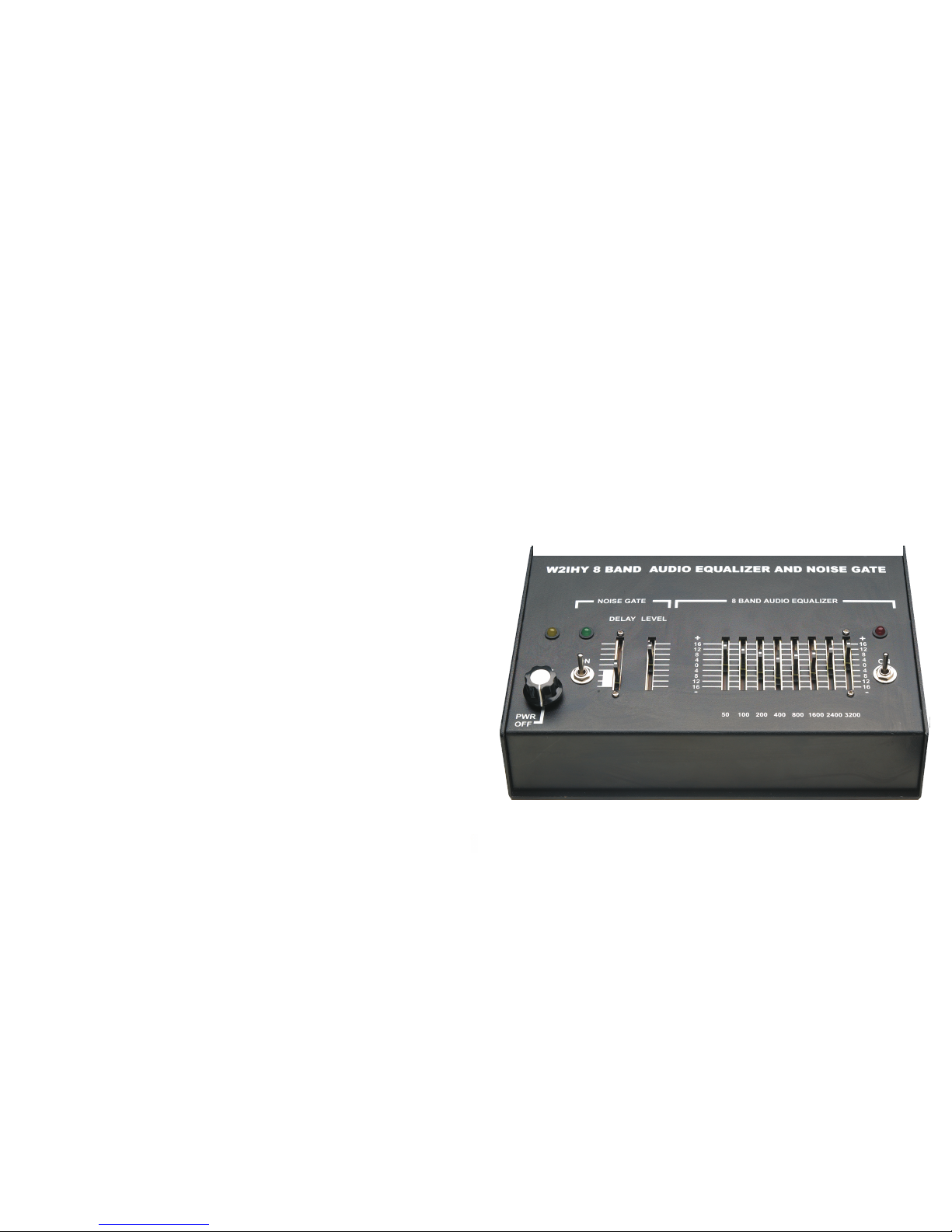
FRONT PANEL CONTROLS
(4) Equalizer CONTROLS (R11-R18)
(5) Noise Gate On / Off Switch (S2)
(6) Noise Gate LED (LED1)
These slide potentiometers work only when the Equalizer On/Off
Switch S3 is in the on position. The potentiometers control
the output of 8 bandpass filters. The center frequency of these
filters are 50 Hz, 100 Hz, 200 Hz, 400 Hz, 800 Hz, 1600 Hz,
2400 Hz and 3200 HZ. The scale, for setting these potentiometers,
is calibrated between -16 db. to + 16 dB. Pushing a potentiometer
forward (up) will increase the output of the equalizer within the
bandpass of the filter whose slide potentiometer is changed.
Pushing a potentiometer backward (down) will decrease the
output of the equalizer within the bandpass of the filter whose
slide potentiometer is changed. Setting all 8 potentiometers at the
zero marking will produce audio at about the same output level
as when the Equalizer On/Off Switch S3 (3) is in the off position.
Adjusting the equalizer 50 Hz, 100 Hz and 200 Hz slide pots
affects the heaviness / weight of the audio. Adjusting the equalizer
400 Hz and 800 Hz slide pots affects the warmth of the audio.
Adjusting the equalizer 1600 Hz, 2400 Hz and 3200 Hz slide
pots affects the clarity and presence of the audio.
This switch turns the noise gate on and off. When the noise
gate is off changing the gate delay or level controls has
no effect on the audio. When the noise gate is off audio is
always being passed (gated) through the noise gate to the output.
This LED is used to help properly adjust the noise gate level
control and to indicate when audio is being sent (gated) to the
output. The LED being on (green) indicates that audio is being
gated through the unit to the output. The LED being off indicates
that audio is not being passed (gated) through to the output.
When the Noise Gate On / Off Switch (5) is in the off position the
noise gate LED is on.
-8-
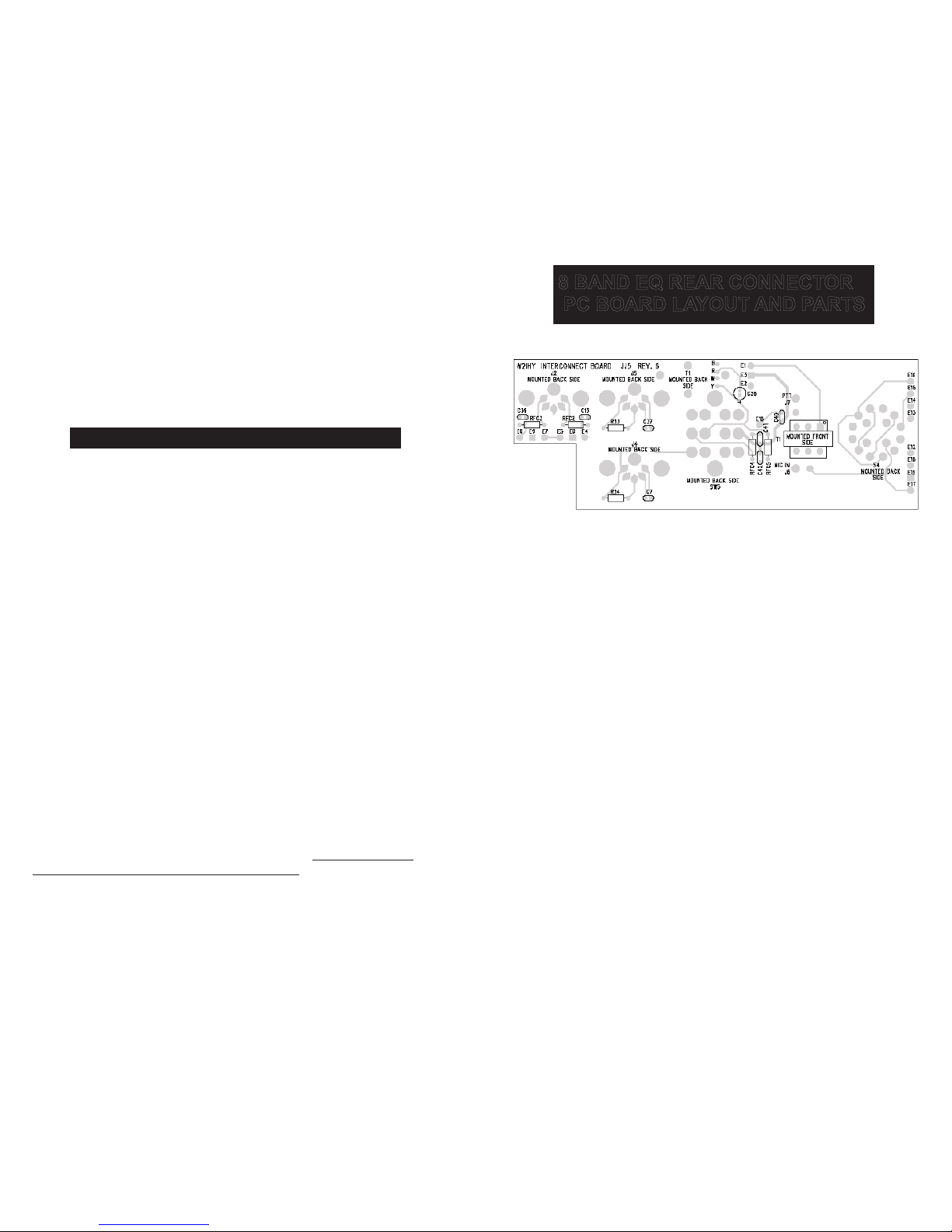
8 BAND EQ MOTHER BOARD
PC BOARD LAYOUT AND PARTS
-21-
* Parts mounted on pin side of P.S. Board
C1,C3, C4,C6,C14, C25-C28, C33 4.7 uF radial electrolytic
C7*, C13*, C16, C17, C32 .1 uF ceramic monolithic
C8 - 22 uF radial electrolytic
C9, C29 - 4.7 uF non polarized radial electrolytic
C10, C11, C12, C15, C31 - 100 uF radial electrolytic
C2, - 10 uF radial electrolytic
C4 - 1 uF radial electrolytic
C18 - C20 - .1 uF mylar
C5 - .033 uF mylar
C23 - C24 - 470 uF radial electrolytic
C21, C34 - .01 uF mylar
C36 - 120 pf ceramic
C22, C35 - .001 uF mylar
D1, D2 - 1N914
D3 - 1N4001
LED1 - Green LED; LED2 - Red LED; LED3 - Amber
Q1 - 2N3417
REG 1 - 7805 with heat sink
Rfc1 - 470 uH R.F. choke
R1, R2, R22 - 10K ohm 5 Resistor 10 pin SIP
R3 - 100 ohm 5 Resistor 10 pin SIP
R4 - 1K ohm 5 Resistor 10 Pin SIP
R5, R6, R27, R30 - 10 ohm ¼ watt 5% Resistor
R7, - 6.8K ohm ¼ watt 5% Resistor
R8, R9 - 5.6K ohm ¼ watt 5% Resistor
R10 - 10K ohm ¼ watt Resistor
R11 - 2.2K ohm ¼ watt Resistor
R12 - 100K ohm horizontal Pot mounted on PC board
R13 - 20K ohm horizontal Pot mounted on PC board
R19 - 33K ohm ¼ watt 5% Resistor
R14 - 75K ohm ¼ watt 5% Resistor
R15* - R17* - 25K ohm Slide Pot
R18* - 5K ohm Slide Pot
R21 - 680 ohm 5 Resistor 10 Pin SIP
R23 - 200 ohm ¼ watt 5% Resistor
R20, R24, R25, R33*. R34* - 47K ¼ watt 5% Resistor
R26 - 0 Ohms (Piece of wire)
R28 - 22K ohm 5 Resistor 10 pin SIP
R29* - 10K Pot with Switch (Used for volume control)
R31 - 1K ohm ¼ watt Resistor
R32 - 33K ohm ¼ watt 5% resistor
U1, U5 - Tl074 or JRC2060; U2 - 74HC00;
U3 - 74LS123;U4- 74HC4053; U6 - LM 386-1