WIN Enterprises MB-60470 User manual
1
Quick Setup Installation Guide
Version 1.3
Model: MB-60470
EBX Form-Factor SBC: Low-Power AMD Opteron Processor PCI Express Slot, CompactFlash
Socket, ExpressCard Socket, 4x SATA, and Stackable HyperTransport Connector

2
Table of Contents
Chapter 1. General Information…………………………………………………………………….. 2
1.1 Introduction………………………………………………………………………………………… 2
1.2 Precautions……………………………………………………………………………………….. 2
Chapter 2. Layout………………………………………………………………………………………. 4
2.1 Board Layout……………………………………………………………………………………….. 4
2.2………………………………………………………………………………………………………… 5
2.3………………………………………………………………………………………………………… 6
2.4 Connector & Jumper Settings……………………………………………………………………… 7
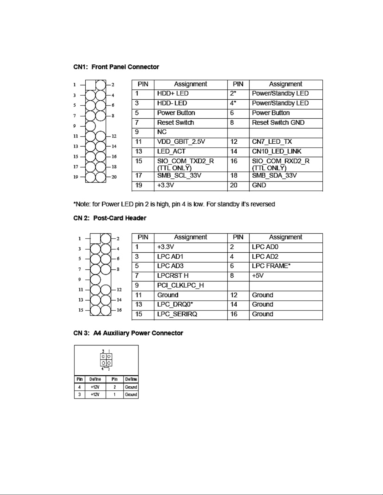
CN1 Front Panel Connector…………………………………………………………………… 7
CN2 Post-Card Header……………………………………………………………………. 7
CN3 A4 Auxiliary Power……………………………………………………………………. 7
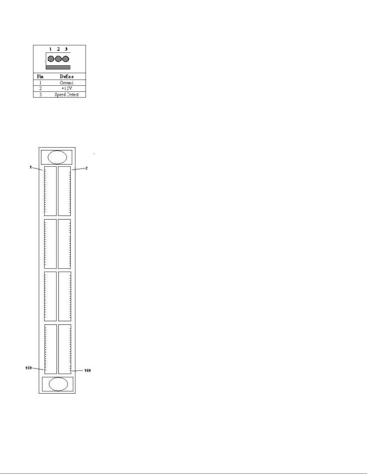
CN4/5 Fan Connector ……………………………………………………………… 8
CN 8 HyperTransport Connector ………………………………………………… 8
CN11 LVDS………………………………………………………………………….. 11
CN12/CN13/CN15/CN16…………………………………………………………… 12
CN22 USB Connector…………………………………………….……………….. 13
CN23 GPIO…………………………………………………………………………… 14
Jumpers: Definitions and Locations………………………………………………. 15
JP1 Flash Recovery………………………………………………………………… 15
JP2 LCD Voltage……………………………………………………………………. 15
JP3 Clear CMOS…………………………………………………………………..…. 15
Appendix A. Switches and Jumpers………………………………………………………… 16
Appendix B: LVDS LCD Voltage……………………………………………………………. 17

3
Chapter 1. General Information
1.0 Introduction
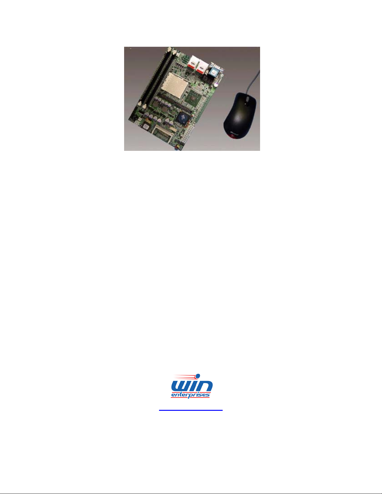
The MB-60470, featuring a PCI Express slot and a stackable HyperTransport connector, is a long-life AMD
Opteron-based reference design for the embedded market. With its EBX small form factor and support for
dual-core processors, MB-60470 is ideal for demanding networking, imaging, storage, and gaming
applications, and other intense applications. The AMD reference design is available as a commercial, off-the-
shelf (COTS) controller or as part of a complete embedded platform. It can be customized in OEM quantities.
1.1 Specifications
Core Features
CPU AMD Opteron Processors HE (55W) and EE (30W). Supports Dual Core CPUs.
Chipset nVidia nForce Professional 2200
Memory Up to 8 GB DDR RAM
I/O
Serial Port One Serial Port
USB Supports Four USB Ports, 2.0 Compliant
PCI Express Right-Angle 16-Lane PCI Express Slot
HyperTransport Stackable HyperTransport Connector
ExpressCard Optional: ExpressCard Socket
Networking
Ethernet Two 10/100/1000 Gigabit Ethernet Ports
Storage
SATA Four SATA II Interfaces
Flash Storage One 50-pin CompactFlash Socket
Audio / Video
Audio Onboard Audio: AC-97 Codec ALC850
Video Onboard SMI VGA Controller
Mechanical & Environmental
Electrical Power Input: ATX Power Supply
Mechanical Board Size: ETX Form Factor: 5.75" x 8.00" (146 mm x 203 mm)
Environmental Operating Temperature: 32 to 122° F (0 to 50° C)
Additional Support
Software Drivers Windows 95, 98, 2000, NT, XP, NT Embedded, XP Embedded, and 64-bit Windows XP
Professional x64. Several Linux distributions are also supported, including 64-bit Debian
Linux.
Customization WIN Enterprises offers several customization options for all standard products. The core
module of this design can serve as the basis for a new design to meet your specific
requirements and speed your time-to-market. WIN offers full design, manufacturing,

4
fulfillment, and support services to ensure the success of all product launches and product
lifecycles.
Ordering Information
MB-60470 WIN EBX Form Factor Controller: AMD Opteron processor with nVidia chipset
CO-01030-1 Heatsink and fan for CPU and Chipset cooling
Please make sure the following items have been included in the package before installation:
MB-60470 Low Power Embedded SBC
Drivers CD
If parts are missing or damaged, please contact your distributor or sales representatives immediately. Save the
shipping materials and carton in the event that you want to ship or store the board in the future. After you
unpack the board, inspect it to assure an intact shipment. Do not apply power to the board if it appears to have
been damaged.
Leave the board in its original packing until you are ready to install
1.2 Precautions
Please make sure you properly ground yourself before handling the MB-60470 board or other system
components. Electrostatic discharge can be easily damage the MB-60470 board.
Do not remove the anti-static packing until you are ready to install the MB-60470 board. Ground yourself
before removing any system component from it protective anti-static packaging. To ground yourself, grasp the
expansion slot covers or other unpainted parts of the computer chassis.
Handle the MB-60470 board by its edges and avoid touching its components.

5
Chapter 2: Layout
2.1 Board Layout
6
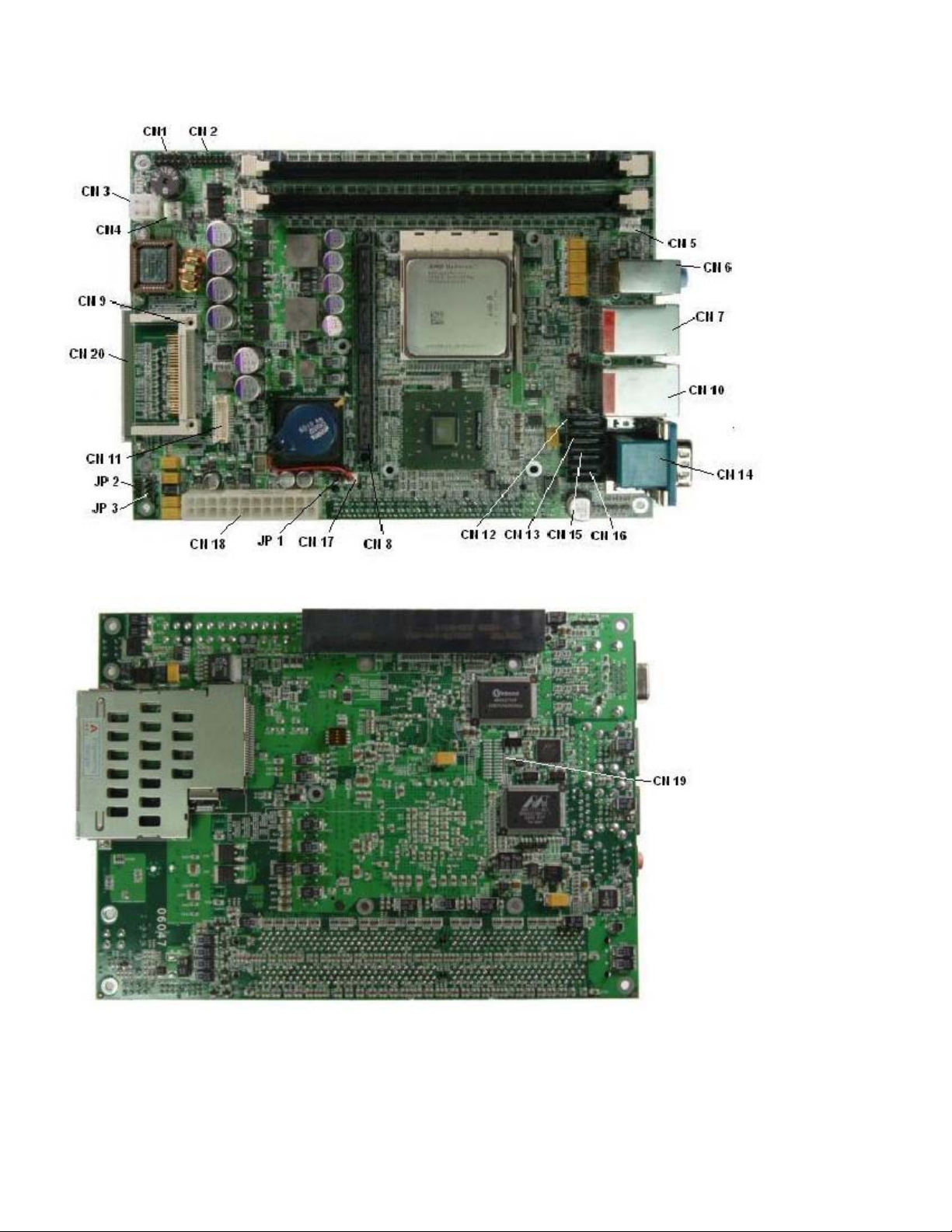
2.2 Connectors Location

7
2.3 Location of Connectors / Jumpers and Definitions
Connector Define Connector Define
CN1 Front Panel CN14 Video + Comport
CN2 Post-Card Header CN15 SATA Connector
CN3 P4 Auxiliary Power Connector CN16 SATA Connector
CN4 Fan Connector CN17 Battery Header
CN5 Fan Connector CN18 ATX Power Connector
CN6 Audio CN19 AMD Hardware bug
Connector
CN7 LAN/USB CN20 Card Express
CN8 Hypertransport Connector CN21 SMBUS Data Connector*
CN9 CompactFlash Socket CN22 USB Connector
CN10 LAN/USB 2 CN23 GPIO Connector
CN11 LVDS Connector JP1 Flash Recovery
CN12 SATA Connector JP2 LCD Voltage
CN13 SATA Connector JP3 Clear CMOS
* SMBUS data connector has been removed from the latest revision of the board
8
2.4 Connector Settings
9
CN4/5: FAN Connector
CN 8: HyperTransport Connector

10
Assignment PIN Assignment
1 3.3V 2 3.3V
3 3.3V 4 3.3V
5 3.3V 6 3.3V
7 TDI 8 HT_REFCLK100
9 USERA0/A0’ 10 TMS
11 USERB0/B0’ 12 USERC/C0
13 USERD0/D0’ 14 SMBCLK
15 USERE0/E0’ 16 SMBDAT
17 TRST 18 GND
19 TCK 20 HT_TX_CADp0
21 GND 22 HT_TX_CADn0
23 HT_TX_CADp8 24 GND
25 HT_TX_CADn8 26 HT_TX_CADp1
27 GND 28 HT_TX_CADn1
29 HT_TX_CADp9 30 GND
31 HT_TX_CADn9 32 HT_TX_CADp2
33 GND 34 HT_TX_CADn2
35 HT_TX_CADp10 36 GND
37 HT_TX_CADn10 38 HT_TX_CADp3
39 GND 40 HT_TX_CADn3
41 HT_TX_CADp11 42 GND
43 HT_TX_CADn11 44 HT_TX_CLK0p
45 GND 46 HT_TX_CLK0n
47 HT_TX_CLK1p 48 GND
49 HT_TX_CLK1n 50 GND
51 GND 52 HT_TX_CADp4
53 HT_TX_CADp12 54 HT_TX_CADn4
55 HT_TX_CADn12 56 GND
57 GND 58 HT_TX_CADp5
59 HT_TX_CADp13 60 HT_TX_CADn5
61 HT_TX_CADn13 62 GND
63 GND 64 HT_TX_CADp6
65 HT_TX_CADp14 66 HT_TX_CADn6
67 HT_TX_CADn14 68 GND
69 GND 70 HT_TX_CADp7
71 HT_TX_CADp15 72 HT_TX_CADn7
73 HT_TX_CADn15 74 GND
75 GND 76 HT_TXCTL0p
77 USER_TCTL1p 78 HT_TXCTL0n
79 USER_TCTL1n 80 GND
81 GND 82 USER_RCTL1n
83 HT_RX_CTL0n 84 USER_RCTL1p
85 HT_RX_CTL0p 86 GND
87 GND 88 HT_RX_CADn15
89 HT_RX_CADn7 90 HT_RX_CADp15
91 HT_RX_CADp7 92 GND
93 GND 94 HT_RX_CADn14
Table of contents
Other WIN Enterprises Computer Hardware manuals

WIN Enterprises
WIN Enterprises MB-64000 User manual

WIN Enterprises
WIN Enterprises MB-73400 User manual

WIN Enterprises
WIN Enterprises MB-63020 User manual

WIN Enterprises
WIN Enterprises PL-01030 User manual

WIN Enterprises
WIN Enterprises MB-60480 User manual

WIN Enterprises
WIN Enterprises MB-73320 User manual
Popular Computer Hardware manuals by other brands

EMC2
EMC2 VNX Series Hardware Information Guide

Panasonic
Panasonic DV0PM20105 Operation manual

Mitsubishi Electric
Mitsubishi Electric Q81BD-J61BT11 user manual

Gigabyte
Gigabyte B660M DS3H AX DDR4 user manual

Raidon
Raidon iT2300 Quick installation guide

National Instruments
National Instruments PXI-8186 user manual


