
7
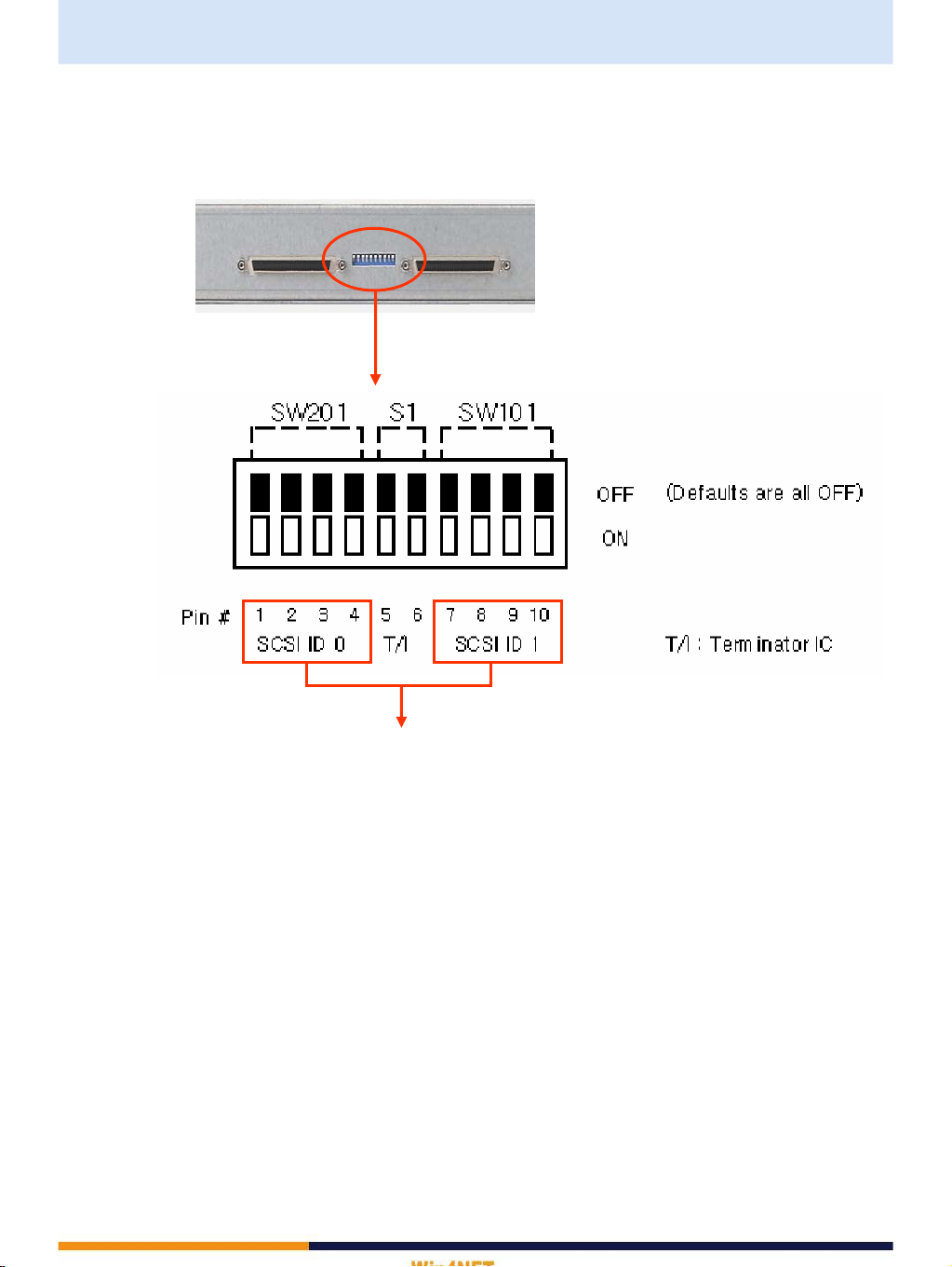
2. DIP SWITCH SETTING
2-1 DIP SWITCH Setting ( except Terminator IC Setting )
* Caution!
- Do not change DIP switch setting while storage boxes are working.
(To change the DIP switch setting, you have to turn off both DVR and storage boxes.)
- Do not connect SCSI cable to the SCSI output port of last storage box.
- If you change the DIP switch setting while working, the stored data will be gone or operating
system won’t work properly.
Ref>
If you want to set 7 storage boxes, each storage box has to be set like pictures as next page.
⑦ Dip Switch Setting
(When 7 storage boxes are connected to DVR, the seventh
storage box DIP set like picture on the right. Other boxes set
same way of the above.)
⑥ Dip Switch Setting
(When 6 storage boxes are connected to DVR, the sixth
storage box DIP set like picture on the right. Other boxes set
same way of the above.)
⑤ Dip Switch Setting
(When 5 storage boxes are connected to DVR, the fifth storage
box DIP set like picture on the right. Other boxes set same way
of the above.)
④ Dip Switch Setting
(When 4 storage boxes are connected to DVR,
the forth storage box DIP set like picture on the right. Other
boxes set same way of the above.)
③ Dip Switch Setting
(When 3 storage boxes are connected to DVR, set the first and
second box like picture ①, ②, and set the third box like picture
on the right.)
② Dip Switch Setting
(When 2 storage boxes are connected to DVR,
set the first box like picture ① and the second box like picture
on the right.)
① Dip Switch Setting
(When 1 storage box is connected to DVR, set the DIP switch
like picture on the right.)


 user manual")


