Wind River Spas Novato WR1466 Series User manual

70" Novato™
NOTE: These are approximate measures. They do not include amps and wattage used by the
light kit.
3.08 ft.
Watts RPM CFMSpeed Volts Amps N.W. G.W. C.F.
High
Extra High
120
Low
Medium Low
Medium
Medium High
0.22
0.31
0.10
0.11
0.14
0.17
14.1
21.5
4.9
6.2
8.1
10.8
91
105
50
60
70
80
5759
6876
2944
3533
4297
5139
10.5 kgs
(23.1 lbs)
11.9 kgs
(26.2 lbs)
Read and save these instructions
Questions, problems, missing parts? Before returning to your retailer,
call our customer service department at 855-817-WIND (9463)
8 a.m. - 5 p.m., EST, Monday-Friday
E-mail: [email protected]
WR1466 SERIES
4406440101000

Begin installation
Tools Required: Phillips screw driver; slotted screw driver; pliers; wire cutters; electrical tape.
MOUNTING OPTIONS
If there isn't an existing outlet box, then read the following instructions. Shut the power off at the circuit
breaker or fuse box.
Secure the outlet box directly to the building structure. Use appropriate fasteners and building materials.
Only use a U.L. Listed metal outlet box marked "Acceptable for ceiling fan support" to install the ceiling fan.
Do not use a plastic outlet box or other device.
Figures 1,2 and 3 are examples of different ways to mount the outlet box.
Note: Please contact with dealer or Wind River at 855-817-WIND (9463) if you need a longer downrod to
maintain proper blade clearance when installing on a steep, sloped ceiling.
To hang your fan where there is an existing fixture but no ceiling joist, you may need to install a hanger bar
as shown in Fig. 4.
Package contents
Unpack your fan and check the contents. See page 2. You should have the following items:
1. Downrod assembly (1) 7. Light kit plate (1)
2. Mounting bracket (1) 8. 17W LED assembly (1)
3. Canopy (1) 9. Glass shade (1)
4. Canopy cover (1) 10. Blade (5)
5. Coupling cover (1) 11. Blade bracker (5)
6. Fan motor assembly (1) 12. Transmitter+holder+2 mounting screws+A23 12V battey(1)
13. Loose parts bag containing
A: Machine screw (2) B: Wood screw (2) C: Metal washer (2) D: Lock washer (2) E: Blade screw (16)
F: Fiber washer (16) G: Blade bracker screw (11) H: Wire nuts (3) J: Safety bolt (1) K: Nut (1)
L: Balancing kit (1)
Safety tips
1. To reduce the risk of electric shock, ensure electricity has been turned off at the circuit breaker or fuse
box before beginning.
2. All wiring must be in accordance with the National Electrical Code “ANSI/NFPA 70-1999” and local
electrical codes. Electrical installation should be performed by a qualified licensed electrician.
3. The outlet box and support structure must be securely mounted and capable of reliably supporting a
minimum of 35 lbs. Use only UL Listed outlet boxes marked “FOR FAN SUPPORT.”
4. The fan must be mounted with a minimum of 7 ft. clearance from the trailing edge of the blades to the
floor.
5. After making electrical connections, spliced conductors should be turned upward and pushed carefully up
into the outlet box. The wires should be spread apart with the grounded conductor and the
equipment-grounding conductor on one side of the outlet box and ungrounded conductor on the other side
of the outlet box.
6. All setscrews must be checked and retightened where necessary before installation.
WARNING: To reduce the risk of electrical shock or fire, do not use this fan with any solid-state fan
speed control device. Please contact with dealer or Wind River at 855-817-WIND (9463) if using
solid-state remote.
WARNING: To reduce the risk of fire, electric shock, or personal injury, mount the fan to the outlet
box marked acceptable for fan support with the screws provided with the outlet box.
1

Outlet box Outlet box Outlet box
Hanger bar
Provide strong
support
Angled ceiling
maximum 18°
angle
Ceiling mounting
plate
Recessed
outlet box
FIG. 1 FIG. 2
FIG. 3 FIG. 4
2
13 Loose part
F H KG
E
1
2
3
4
5
6
7
8
9
10
11
12
A C
B
D I J

Hanging the fan
WARNING: Please use all of the parts hardware and components provided by Wind River. The use of
other parts, hardware or components not supplied by Wind River with the fan will void the Wind River
Warranty.
REMEMBER to turn off the power. Follow the steps below to hang your fan properly:
Step 1. Secure the mounting bracket to the ceiling outlet box using screws and washers included with
mounting hardware. (Fig.5)
Stpe 2. Lossen the two set screws from the top coupling of the motor assembly. (Fig 6)
Step 3. Remove hanger ball from downrod assembly by loosening set screw, removing the cross pin, and
sliding ball off rod. (Fig 6)
Step 4. Carefully feed fan wires up through the downrod (Fig 6). Screw the downrod into the coupling. Insert
the saftey bolt through the coupling and attach the nur.Tighten firmly. Tighten set screws.
Step5. Slip coupling cover, canopy cover, and canopy onto downrod (Fig.6).Carefully reinstall hanger ball
onto rod being sure that cross pin is in the correct position, set screws are tighten and wires are not twisted.
Step 6. Now lift motor assembly into position and place hanger ball into hanger bracket. Rotate until the
check groove has dropped into the registration slot and seats firmly. (Fig 7) Rod should not rotate if this is
done correctly.
Electrical connections
REMEMBER to shut the power off at the circuit breaker or fuse box.
Follow the steps below to connect the fan to your house supply wires. Use the wire nuts supplied with your
fan. Secure the wire nuts by wrapping the connection with electrical tape.
Step 1. Connect the black (hot) wire from the ceiling to the black wire from the fan. Connect the white
(Neutral) wire from the ceiling to the white wire from the fan. (Fig 8)
Step 2. If your outlet has a ground wire (Green or Bare Copper) connect the fan ground wires (from hanger
ball and mounting bracket) to it; otherwise connect the fan ground wire wires from the hanger ball and
mounting bracket together. (Fig. 8)
Finishing the installation
Step 1. Remove one screw from the mounting bracket and loosen the other screw approximately 1/4 turn.
Step 2. Carefully raise the canopy up to the mounting bracket, and ensure the loosened screw is inserted
into the key hole on the canopy. Rotate the canopy clockwise. (Fig. 9)
Step 3. Secure the canopy by replacing the screw previously removed and tightening the screw previously
loosened. (Fig. 9)
Step 4. Place the canopy cover on the canopy, and rotate the canopy cover clockwise until it locks into
position. (Fig. 9)
Blade installation
Step 1. Attach the fan blades to the blade brackers by using three blade screws and fiber washers. Tighten
screws and fiber washers securely.(Fig.10)
Step 2. Attach the blade assembly to the fan motor assembly by tightening the two screws previously from
the package hardware. Repeat the process for the other blade assemblies. (Fig. 11)
3

Mounting
bracket
Set screw
Registration
slot
Cross pin
Canopy
Canopy
Canopy
cover
Canopy cover
Coupling
cover
Coupling
Black (Motor) White (Neutral)
Black(Hot)
White (Neutral) Green (Ground)
Green (Ground)
Ceiling
House wire supply
Mounting bracket
Blade bracket
Blade bracket
Blade bracket screw
Fan motor assembly
Blade
Blade screw
Fiber washer
Set screw
Set screw
Nut
Safety bolt
FIG. 5 FIG. 6 FIG. 7
FIG. 8
FIG. 11FIG. 10
FIG. 9
4

Installing the light kit plate
Step1. Remove 1of 4 screws from the mounting ring and loosen the other 3 screws.(Do not remove.)
(Fig.12)
Step2. Place the key holes from the light kit plate over the 3 screws previously loosened from the mounting
ring , turn light kit plate until it locks in place at the narrow section of the key holes. Secure by tightening the
3 screws previously loosened and the one previously removed.(Fig.12)
Installing the 17W LED assembly
WARNING: Shut of the power supply before removing or replacing lamp. If you accidentally come into
contact, wipe thoroughly with a clean, lint-free, cotton cloth. Use light bulb in accordance with the fan’s
specification.TO REDUCE THE RISK OF FIRE DO NOT EXCEED MAXIMUM WATTAGE RATING.
Step1. Remove 1of 3screws from the light kit plate and loosen the other 2 screws.(Do not remove.) (Fig.13)
Step2. Connect white wire from motor to white wire from the 17W LED assembly. Connect black wire from
motor to black wire from the 17W LED assembly. (Fig. 13)
Step3. Place the key holes from the light kit plate over the 2 screws previously loosened from the mounting
ring , turn light kit plate until it locks in place at the narrow section of the key holes. Secure by tightening the
2 screws previously loosened and the one previously removed.(Fig.13)
Installing the glass shade
Attach the glass shade to the light kit plate by twisting tightly.(Fig. 14)
Operation
Begin testing the fan functions with the remote control (Figure 15). See operation details below.
• Fan Buttons 1-6: The higher the number the faster the fan should turn. Press one time on each button to
the desired speed. #1 is the lowest speed and #6 is the highest speed.
• Fan Off Button: Press once to turn fan off.
• Light Button: Press once to turn light on/off.
• Reverse Button: Is in the back of the hand held by the battery compartment (Fig 16). Press once to
reverse the fan.
NOTE: To operate the reverse function on this fan, press the reverse function button while the fan is
running.
Warm weather - (Counterclockwise Direction) A downward air flow creates a cooling effect. This allows you
to set your air conditioner on a higher setting without affecting your comfort. (Fig 17)
Cool weather - (Clockwise Direction) An upward air flow moves warm air off the ceiling. This allows you to
set your heating unit on a lower setting without affecting your comfort. (Fig 18)
Care and Cleaning
Check the support connections, brackets, and blade attachments twice a year. Ensure they are secure.
Because of the fan’s natural movement, some connections may become loose over time. It is not necessary
to remove the fan from the ceiling.
Clean your fan periodically. Use only a soft brush or lint-free cloth to avoid scratching the finish. The plating
is sealed with a lacquer to minimize discoloration or tarnishing.
(Optional) Apply a light coat of furniture polish to the wood blades.
(Optional) Cover small scratches with a light application of shoe polish.
Do not use water when cleaning. Water could damage the motor, or the wood, or possibly cause an
electrical shock.
Do not apply oil to your fan or motor. The motor has permanently-lubricated sealed ball bearings.
5 4 5
3

Reverse button
Glass shade
17W LED assembly
Black wire
connectors White wire
connectors
Screw
FIG. 17 FIG. 18
FIG. 15
FIG. 12 FIG. 13 FIG. 14
FIG. 16
ScrewLight kit plate
Light kit plate
Mounting ring
6

Troubleshooting
Questions, problems, missing parts? Before returning to your retailer,
call our customer service department at 855-817-WIND (9463)
8 a.m. - 5 p.m., EST, Monday-Friday
E-mail: [email protected]
Check that all blade and blade arm screws are secure.
Most fan wobble problems are caused when blade levels are unequal. Check
this level by selecting a point on the ceiling above the tip of one of the blades.
Measure from a point on the center of each blade to the point on the ceiling.
Rotate the fan until the next blade is positioned for measurement. Repeat for
each blade. Measurements deviation should be within 1/8 in. Run the fan for
10 minutes.
Use the enclosed blade balancing kit if the blade wobble is still noticeable.
The fan wobbles.
Problem Solution
Check main and branch circuit fuses or breakers.
Check line wire connections to the fan and switch wire connections in the
switch housing.
Make sure all motor housing screws are snug.
Make sure the screws that attach the fan blade arm to the motor hub are tight.
Make sure wire nut connections are not rattling against each other or the
interior wall of the switch housing.
Allow a 24-hour "breaking-in" period. Most noises associated with a new fan
disappear during this time.
If using the ceiling light kit, make sure the screws securing the glassware are
tight. Check that the light bulb is also secure.
Make sure there is a short distance from the ceiling to the canopy. It should
not touch the ceiling.
Make sure your ceiling box is secure and rubber isolator pads are used
between the mounting bracket and outlet box.
The fan will not start.
The fan sounds noisy.
7

3.08 ft.
RPM CFM N.W. G.W. C.F.
Alto
Más alta
120
Baja
Medio-bajo
Mediana
Medio-alto
0.22
0.31
0.10
0.11
0.14
0.17
14.1
21.5
4.9
6.2
8.1
10.8
91
105
50
60
70
80
5759
6876
2944
3533
4297
5139
10.5 kgs
(23.1 lbs)
11.9 kgs
(26.2 lbs)
70" Novato™
NOTA: Estas son mediciones aproximadas. No incluyen los Amperios y vatios usado por el juego
de iliminación.
Lea y guarde estas instrucciones
¿Preguntas, problemas, partes perdidas? Antes de volver a la tienda, llame a nuestro
departamento de servicio al cliente al 855-817-WIND (9463)
8 a.m. - 5 p.m., EST, Lunes-Viernes
E-mail: [email protected]
WR1466 SERIE
4406440101000
VatiosVelocidad Voltios Amperios

Comenzando la instalacion
Herramientas necesarias: Un desarmador plano, un desarmador de cruz, cortadoras de alambre, cinta aislante.
OPCIONES DE MONTAJE
Si no existe una caja de distribucion instalada, siga las siguientes instrucciones. Desconecte la energía
eléctrica apagando los interruptores del circuito o sacando los fusibles.
Asegure la caja de distribucion directamente en la estructura del edificio. Use los soportes y materiales de
construccion apropiados. La caja de distribucion y soporte deben de ser capaces de soportar todo el peso
en movimiento del ventilador (minimo de 35 libras). Use una caja de metal que esté aprovada por UL
marcada "Acceptable for Ceiling Fan Support". No use cajas de distribucion de plástico.
Las ilustraciones 1, 2 y 3 muestran alternativas diferentes para montar la caja de distribucion.
Nota: Por favor, póngase en contacto con el distribuidor o con Wind River en el 855-817-WIND (9463) si
necesita una varilla regulable más larga para mantener la holgur adecuada de las palas cuando lo instale en un
techo inclinado.
Para colgar su ventilador donde anteriormente había una lámpara pero no hay viga, prodria necesitar
instalar una abrazadera de soporte como se muestra en la ilustracion 4.
Contenidos en paquete
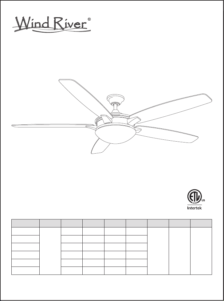
Desembalar el ventilador y revisar el contenido. Vease pagina 2. Debe tener los siguientes elementos:
1. Conjunto de varilla (1) 8. Conjunto LED 17-W (1)
2. Soporte de montaje (1) 9. Pantalla de vidrio (1)
3. Tapa (1) 10. Hoja (5)
4. Tapa de cubierta (1) 11. Soporte de hoja (5)
5. Cubierta de acoplamiento (1) 12. Transmisor con portatransmisores + 2 tornillos de
6. Conjunto de motor de ventilador (1) montaje + bateria A23 de 12 voltios (1)
7. Placa de aparato de luz (1)
12. El bolso de accesorios incluye:
A: Tornillo de máquina (2) B: Tornillo de madera (2) C: Arandela de metálica (2)
D: Arandela de seguridad (2) E: Tornillo de hoja (16) F: Arandela de fibra (16)
G: Tornillo de soporte de hoja (11) H: Tuerca de alambre plástica (3) I: Perno de seguridad (1)
J: Tuerca (1) K: Conjunto de balanceo (1)
Règles de sécurité
1. Para reducir el riesgo de eléctrocución, asegurarse de que la eléctricidad se ha desactivado en el
cortacircuitos o caja de fusibles antes de comen-zar.
2. Todos los cables deben cumplir con el Código Eléctrico Nacional “ANSI/NFPA 70-1999” y los códigos
eléctricos locales. La instalación eléctrica debería realizarla un electricista profesional cualificado.
3. La caja de distribución y la estructura de soporte deben estar montados de manera segura y deben ser
capaces de soportar, de manera confiable, unminimo de 35 libras (15,9 kilogramos). Usar solamente cajas
de distribución listadas por U.L. marcadas "PARA SOPORTEDE VENTILADORES".
4. EL ventilador debe estar montado con un m nimo de 7 pies (213cm) de espacio libre desde el borde
posterior de las aspas hasta el piso.
5.Tras realizar las conexiones eléctricas, los conductores empalmados deberían girarse hacia arriba y
meterse con cuidado en la toma de corriente. Los cables deberían separarse con el conductor a tierra y el
conductor de tierra del equipo por un lado de la toma de corriente y el conductor no conectado a tierra en el
otro lado de la toma de corriente.
6. Todos los tornillos deberían ser comprobados y revisados antes de la instalación.
ADVERTENCIA: Por reducir el riesgo de descargas eléctricas o incendios, no utilice este ventilador
con ningún controlador de velocidad del ventilador de estado sólido. Por favor, póngase en contacto
con el distribuidor o con Wind River llamando al 855-817-WIND (9463) si utilce el el mando de estado
sólido a distancia.
ADVERTENCIA: Para reducir el riesgo de fuego, descarga eléctrica o lesiones personales, monte el
ventilador a una toma de corriente marcada como compatible para soportar un ventilador con los
tornillos incluidos en la toma de corriente.
1

13 Bolso de accesorios
F H KG
E
1
2
3
4
5
6
7
8
9
10
11
12
A C
B
D I J
Caja de
distribucion Caja de
distribucion
Barra para suspension
Proporciona
un soporte
firme
Declive del
techo angulo
maximo de18°
Ceiling mounting
plate
Caja de
distribucion
FIG. 1 FIG. 2
FIG. 3 FIG. 4
2

Terminando la instalacion
Paso 1. Quite un tornillo del soporte de montaje y afioje el otro tornillo por 1/4 de vuelta más o menos.
Paso 2. Levante la tapa con mucho cuidado al soporte de montaje, y comprueba que el tornillo afiojado
haya insertado en el agujero de la llave en la tapa. Gire la tapa en sentido horario. (Fig. 9)
Paso 3. Fije la tapa (C) por reemplazando el tornillo previamente quitado y apretando el tornillo
previamente afiojado. (Fig. 9)
Paso 4. Coloque la cubierta de tapa en la misma y gire la cubierta de tapa en el sentido de la aguja del reloj
hasta que él bloquée en su posición. (Fig. 9)
Instalación de las hojas
Paso 1. Fije las aspas de ventilador en los soportes de hoja por utilizando los tres tornillos de hoja y las
arandelas de fibra. Y apriete los tornillos y las arandelas de fibra firmemente. (Fig.10)
Paso 2. Gire el motor a fin de que los agujeros de los tornillos de motor están alineados con los agujeros en
el soporte de hoja y fije con tornillos adecuados. Repita el proceso para los demás soportes de hoja. (Fig.
11)
Colgando el ventilador
Advertencia: Utilice todas piezas metalicasy componentes proporcionados por Wind River. El uso
de otras piezas metalicas o componentes no suministrados por Wind River con el ventilador, se
anulará la Garantía de Wind River
RECORDAR: Apagar la energia electrica en el circuito principal o en la caja de fusibles:
Paso 1. Fije la soporte de montaje a la caja de salida con dos tornillos y arandelas suministrados con la
caja de salida. Asegúrese de que la soporte de montaje este apretada y asegurada.(Fig.5)
Paso 2. Afioje los dos tornillos de fijación del acoplamiento del conjunto del motor del ventilador del motor.
(Fig 6)
Paso 3. Quite la bola de suspensión de la varilla por afiojando el tornillo de fijación de la bola de
suspensión, y quitando el pasador transversal, entonces deslizando la bola de suspensión fuera de la
varilla. (Fig 6)
Paso 4. Proporcione los cables del ventilador a través de la varilla cuidadosamente. (Fig 6). Atornillo la
varilla en el acoplamiento del conjunto del motor del ventilador. Inserte le perno de seguridad en el
acoplamiento y la varilla e instale la tuerca. Apriete bien. Entonces apriete los tornillos de fijación.
Paso 5. Deslice la cubierta de acoplamiento, la tapa de cubierta, y la tapa en la varilla (Fig.6).Y vuelva a
instalar la bola de suspensión cuidadosamente en la varilla, entonces por favor asegúrese de que el
pasador transversal esté en la posición correcta, los tornillos de fijación estén apretados, y los alambres no
sean torcidos.
Paso 6. Levante el conjunto del motor del ventilador en la posición, y coloque la bola de suspensión en el
soporte de montaje. Gire el conjunto del motor del ventilador hasta que la ranura de prueba estén en la
ranura de registro y lo coloque firmemente.(Fig 7) Debe girar la varilla en caso de falla operación.
Conexiones eléctricas
RECORDAR no se olvide de desconectar la energía eléctrica en el circuito principal o en la caja de
fusibles.
Siga los siguientes pasos para conectar el ventilador a los alambres de la casa que suministran la energía
eléctrica. Use los conectores de alambres que vienen con su ventilador. Para que los conectores queden
firmes, envuelva la conexión con cinta aislante.
Paso 1. Conecte el alambre negro (con corriente)del techo a los alambres negro del ventilador. Conecte el
alambre blanco (NEUTRAL) del techo al alambre blanco del ventilador.(Fig 8)
Paso 2. Si su caja de distribucion tiene un alambre a tierra (verde o de cobre) conecte los alambres a tierra
del ventilador (en la bola de suspensión o soporte de montaje) al alambre a tierra de la caja de distribucion.
Si notiene alambre a tierra en su caja de distribucion, conecte el alambre a tierra de la bola de suspensión
de soporte directamente a la soporte de montaje.(Fig. 8)
3

FIG. 11FIG. 10
Tornillos fijos
Tornillos fijos
Tornillos fijos
Ranura de
registro
El pasador
transversal
Tapa
Tapa
Tapa de cubierta
Tapa de
cubierta
Cubierta de
acoplamiento
Acoplamiento
Negro (Motor)
Negro (Con Corriente)
Blanco(Neutral)
Blanco(Neutral)
Verde (A tierra)
Verde (A tierra)
TECHO
Alambrado electrico de la casa
Soporte de montaje
Soporte de
montaje
Soporte de hoja
Soporte de hoja
Tornillo de soporte de hoja
Conjunto de motor
de ventilador
Hoja
Tornillo de hoja
Arandela de fibra
FIG. 5 FIG. 6 FIG. 7
FIG. 8 FIG. 9
4
Tuerca
Perno de
seguridad

Instalación el placa de conjunto de luz
Paso 1. Quite 1 de 4 tornillos del anillo de montaje y afloje los otros 3 tornillos. (No los quite) (Fig.12)
Pasp 2. Coloque los principales agujeros de la placa de conjunto de luz sobre los 3 tornillos previamente
aflojados en el anillo de montaje, gire la placa de conjunto de luz hasta que encaje en su lugar en la
sección estrecha de los principales agujeros. Apriete los 3 tornillos previamente aflojados y el previamente
eliminado. (Fig.12)
Instalación del conjunto LED 17-W
ADVERTENCIA: Cierre de la fuente de alimentación antes de retirar o reemplazar la lámpara. Si
accidentalmente entra en contacto, limpie cuidadosamente con una tela de algodón limpia, libre de pelusa.
Utilice bombillas de conformidad con la especificación del ventilador. PARA REDUCIR EL RIESGO DE
INCENDIO NO EXCEDA LA POTENCIA MÁXIMA.
Paso 1. Quite 1 de 3 tornillos del placa de conjunto de luz y afloje los otros 2 tornillos. (No los quite)
(Fig.12)
Paso 2. Conecte el alambre blanco del conjunto del motor del ventilador al alambre blanco del conjunto
LED 17-W. Conecte el alambre negro del conjunto del motor del ventilador al alambre negro del conjunto
LED 17-W. (Fig.13)
Paso 3. Coloque los principales agujeros de la conjunto LED 17-W sobre los 2 tornillos previamente
aflojados en el placa de conjunto de luz, gire la conjunto LED 17-W hasta que encaje en su lugar en la
sección estrecha de los principales agujeros. Apriete los 2 tornillos previamente aflojados y el previamente
eliminado. (Fig.13)
Instalar la pantalla de vidrio
Fije la pantalla de vidrio en la placa del conjunto de luz por torciendo fuertemente. (Fig. 14)
Operación
Comience evaluando las funciones del ventilador con el mando a distancia (Fig 15). Ver detalles de la
operación más adelante.
• Botones del ventilador 1-6: el número máximo será más rápido para los giros del ventilador. Pulse de
una vez en cada botón de la velocidad deseada. # 1 es la velocidad más baja y # 6 es la velocidad más
alta.
• Botón apagado de ventilador: Presione una vez para apagar ventilador.
• Botón de luz: Pulse una vez para encender la luz de encendido / apagado.
• Botón Revés: Está en la parte posterior de compartimiento de la batería (Figura 16). Pulselo de una vez
para invertir el ventilador.
NOTA: Para utilizar la función inversa de este ventilador, presione el botón de función inversa cuando el
ventilador está en funcionamiento.
Clima cálido - (Adelante) Una corriente de aire descendente crea un efecto refrescante como se muestra en.
Esto le permite ajustar su aire acondicionado en un mayor ajuste sin que ello afecte su comodidad. (Fig 17)
Clima Frío - (Inversa) Un fiujo de aire mueve el aire caliente hacia arriba fuera de la zona límite, como se
muestra en. Esto le permite configurar su unidad de calefacción en un ajuste más bajo sin afectar a su
comodidad. (Fig 18)
Cuidado y Limpieza
Verifique las conexiones de soporte, soportes y equipos de hoja dos ves por un año. Y asegúrese de
fijarlos bien. Debido al movimiento natural del ventilador, unas conexiones puedan afiojarse por un tiempo.
No es necesario de quitar el ventilador del techo.
Limpie el ventilador periódicamente. Sólo utilice un paño suave o libre de hilas para evitar la rascadura del
acabado. El revestimiento se selle con barniz para minimizar la descoloración o deslustre.
(Opcional) Aplique una capa ligera de lustre de mueble en las hojas de madera.
(Opcional) Cubre las rascaduras pequeñas con unos lustres de zapatos.
No pueda utilizar aguas a la limpieza. El agua pueda dañar el motor, la madera o causar un choque
eléctrico posiblemente.
No pueda aplicar aceite en el ventilador o el motor. Los rodamientos de bolas del motor han sido lubricados
permanentemente.
5 4 5
3

Alambre negro
Botón Revés
Conjunto LED 17-W
Alambre blanco
FIG. 17 FIG. 18
FIG. 15
FIG. 12 FIG. 13 FIG. 14
FIG. 16
Anillo de
montaje
Tornillo
Tornillo
Pantalla de vidrio
6
Placa de aparato
de luz
Placa de
aparato
de luz

Solución de averías
¿Preguntas, problemas, partes perdidas? Antes de volver a la tienda, llame a nuestro
departamento de servicio al cliente al 855-817-WIND (9463)
8 a.m. - 5 p.m., EST, Lunes-Viernes
E-mail: [email protected]
Verifique si todas las hojas y los tornillos de brazo de hoja sean fijados.
La mayoría de los problemas sobre la oscilación es causada cuando los
niveles de hoja son irrgulares. Veri�que el nivel por seleccionando un punto
del techo encima del extremo de una de las hojas. Y tome la medidas desde
un punto en el centro de caja hoja al punto del techo. Gire el ventilador hasta
que la hoja siguiente sea situada para la medida. Repite por caja hoja. La
desviación de las medidas debe estar dentro de 1/8 pulgadas. Y funcione el
ventilador por diez minutos.
Utilice el conjunto de balanceo de hoja adjuntivo si la oscilación de hoja
todavía es notable.
Las oscilaciones de
ventilador
Problema Solución
Revisar los fusibles o interruptores de circuitos.
Verificar las conexiones de cables de linea al ventilador y conexiones de
cable del interruptor.
Asegurarse de que todos los tornillos de la cubierta del motor estén ajustados.
Asegurarse de que los tornillos que sujetan el soporte de aspas del ventilador
al eje del motor estén apretados.
Asegurarse de que las conexiones de tuercas para cable no esten rozando
unas contra otras o contra la pared interior de la cubierta protectora del
interruptor.
Permitir un período de "desgaste" de 24 horas. La moyaría de los ruidos
asociados con un ventilador nuevo desaparecen durante este tirmpo.
Si se está usando un juego opcional de iluminación para el venitlador de
techo, aseguarse de que los tornillos que aseguran el vidrio estén apretados.
Asimsmo, verificar que la bombilla esté segura.
Asegurarse de que el escudete superior esté a una corta distancia del techo.
No debe hacer contacto con el techo.
Asegúrese de que la caja del techo esté fija y que las almohadillas aislantes
de goma estén colocadas entre el soporte de montaje y la toma de corriente.
El ventilador no funciona
El ventilador emiteruido
7
Table of contents
Languages:
Popular Fan manuals by other brands

UltimateAir
UltimateAir ER80M manual

silavent
silavent Green Line HRX2 Series Installation and operating instructions

Progress Lighting
Progress Lighting P2667 Assembly/installation instructions

Hunter
Hunter Savoy installation manual

Weil-McLain
Weil-McLain STAR-34 Supplement

Lasko
Lasko D300 instruction manual