DuraVent DuraSeal DS User manual

1
3” to 24” Diameter Vent For use on Positive, Neutral and
Negative Pressures up to 35” W.C.
Also for venting listed gas or oil fired appliances listed for
venting with TYPE L low temperature venting system
(DSD / DSID ONLY)
MODEL DuraSeal®DS/DSD/DSID
Single Wall or Double Wall AL29-4C®or 316L.
Special Gas Vent for Category I, II, III and IV.
TYPE L VENT Low temperature venting system
SUBMITTAL RECORD
SFDS REV. 11 08-07-19
Reference to the installationinstructions will enable youto obtain a safe,
efficient and dependable installation of this vent system. Please read
and understand these instructions before beginning your installation.
Do not alter or modify the components of this chimney system under
any circumstances. Any modification or alteration of the vent system
or approved accessories, including but not limited to the appliance
it is connected to, may void the warranty, listings and approvals of
this system and could result in an unsafe and potentially dangerous
installation.
A. Examine all components for possible shipping damage prior to
installation;
B. Proper joint assembly is essential for a safe installation. Follow
these instructions exactly as written: Check severeness of joints
upon completion of assembly;
C. This venting system must be free toexpand and contract. This venting
system must be supported in accordance with these instructions;
D. Check for unrestricted vent movement through walls, ceilings, and
roof penetrations;
E. Different manufacturers have different joint systems and adhesives.
Do not mix pipe, fittings, or joining methods from different manu-
facturers.
Listed to standards:
UL-1738
ULC-S636
UL-641
ULC-S609
Report # G100215896MTL-006
MODEL DS MODEL DSD
MODEL DSID
SUBMITTAL RECORD
PREPARED FOR:
REFERENCE:
LOCATION:
CONTACT:
TELEPHONE: FAX:
EMAIL:
PREPARED BY:
}DSD/DSIDONLY
Material Selection
FLUE (INNER WALL)
AL29-4C
316L

2
TABLE OF CONTENTS
Introduction ................................................................................. page 2
Testing / listing information ......................................................... page 2
Clearances to combustibles ......................................................... page 3
General installation requirements ................................................ page 3
Typical installations .................................................................... page 4-5
Chimney and fitting joint assembly .............................................. page 6
Chimney weight........................................................................... page 6
Support methods and height ....................................................... page 7
Horizontal installation requirements ............................................ page 8
Maintain proper slope ................................................................. page 9
Vertical installation requirements ................................................ page 9
Wall penetration .......................................................................... page 10
Roof / floor penetration ............................................................... page 10
Condensate drains ...................................................................... page 10
DuraSeal as a liner ...................................................................... page 12
Adjustable length ........................................................................ page 13
DuraSeal Flex .............................................................................. page 14
Maintenance instructions............................................................. page 15
DuraSeal Labels........................................................................... page 16
Warranty...................................................................................... page 44
Product reference information...................................................... page 48
INTRODUCTION
DuraSeal®single wall (DS) or double wall (DSD) or double wall insulated
(DSID) is a special stainless steel vent system for gas fired appliances listed
as Category I, II, III, and IV or in Canada as Type BH Gas Venting as noted
in ULC-636, with a maximum operating temperature of 550 Degrees F (288
Degrees C), and a maximum rated positive pressure of 35” Water Column. It
can also vent listed gas or oil fired appliance rated to be vent with TYPE L low
temperature venting system (DSD & DSID only). DuraSeal must be installed
by an experienced professional familiar with the operation and maintenance
of heating appliances and venting. Before installing this product, examine all
components for possible shipping damage and read the complete installation
manual. Failure to follow proper installation procedures, including vent pitch
and improper appliance connections, may cause unsafe conditions. DuraVent
recommends the system to be inspected once a year by a qualified service
technician
TESTING / LISTING INFORMATION
DuraVent DuraSeal model DS, DSD and DSID venting system is listed with
Intertek Testing Services (ETL) to UL/ULC standards:
U.S.A.
• UL-1738
Special Gas Vent for Category I, II, III
and IV appliances
• UL-641 (DSD & DSID only)
TYPE L VENT venting listed gas
or oil burning appliances
CANADA
• ULC-S636
Type BH Gas Vent Class I/II
• ULC-S609 (DSD & DSID only)
TYPE L VENT venting of flue gases with temperature not exceeding 300°C
from oil or gas burning appliances
This product must be installed in accordance with local building code require-
ments as well as National codes: USA - National Fuel Gas code ANSI-Z223.1
or NFPA Standard 54, or NFPA 211. In CANADA - CAN/CGA-B149.1 or CAN/
CGA-B149.2 Propane Installation Code as applicable.

3
CLEARANCES TO COMBUSTIBLES
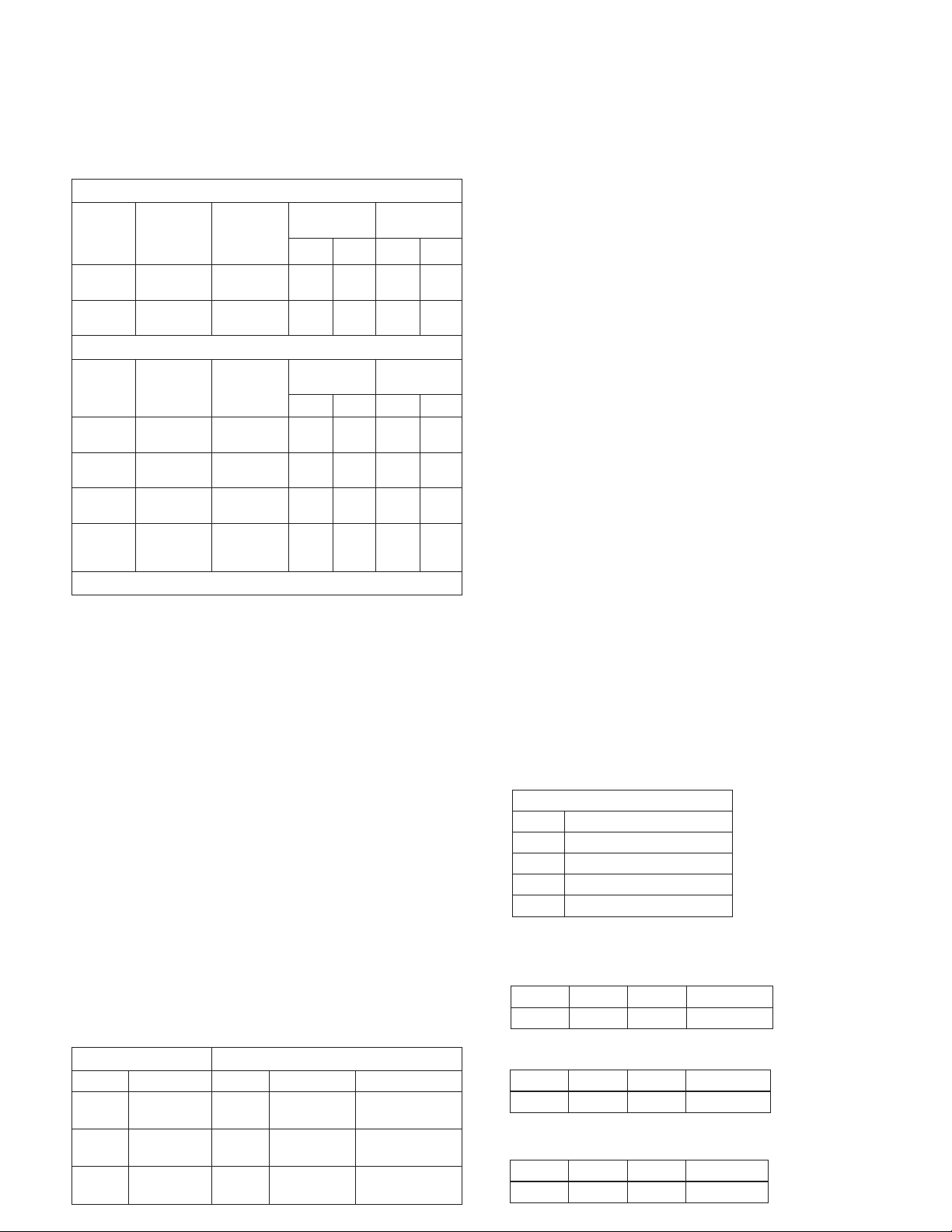
Table 1 shows the required MINIMUM AIRSPACE CLEARANCE TO COMBUS
-
TIBLES. “Combustibles” include framing lumber, drywall, plywood, paneling,
insulation, wiring and other building materials.
Minimum Clearance to Combustibles Single Wall DS
Diameter
Rated
operating
temperature
Max.
operating
temperature
Enclosed
(4 sides)
Unenclosed
(2 sides Max.)
Horiz. Vert. Horiz. Vert.
3” to 12” 480º F
(250º C)
550º F
(288º C) N/A N/A 2” 2”
14” to 24” 480º F
(250º C)
550º F
(288º C) N/A N/A 4” 4”
Minimum Clearance to Combustibles Double Wall DSD / DSID
Diameter
Rated
operating
temperature
Max.
operating
temperature
Enclosed
(4 sides)
Unenclosed
(2 sides Max.)
Horiz. Vert. Horiz. Vert.
3” to 12” 480º F
(250º C)
550º F
(288º C) N/A 1” 1” 1”
14” to 24” 480º F
(250º C)
550º F
(288º C) N/A 1” 3” 1”
3” to 12”
L-VENT
480º F
(250º C)
550º F
(288º C) N/A 2” 2” 2”
14” to
24”
L-VENT
480º F
(250º C)
550º F
(288º C) N/A 2” 3” 2”
Table 1 - Minimum Clearances for DuraSeal®
Auxiliary parts such as combination Roof Supports, Roof Thimble, Flashings
and Wall Thimble outer shields are intended to be attached directly to the
framing or to ceilings, floors, or walls in accordance with their respective
instructions. These parts, which are installed in contact with wood or other
combustibles, are designed and tested to assure that they do not overheat
at points of contact.
Notes:
1. Unenclosed requires at least two sides open.
2. Single Wall (DS) may be enclosed only in non-combustible enclosure.
3. Reduced clearances maybe attained by using non-combustible enclosures.
4. Combustible Material is any material made of or surfaced with wood,
compressed paper, plant fibers or other materials that are capable of being
ignited or burned. Such material shall be considered combustible even
though it is flame-proofed, fire-retardant treated, or plastered. (Source:
NFPA 54/ANSI Z223.1)
5. Design any enclosure to permit inspection of the system.
6. Do not place insulation in any required clearance spaces surrounding the
vent system unless these instructions suggest otherwise and the insulation
is specified or supplied.
7. When using Viton caulking, follow the manufactures required drying times.
GENERAL INSTALLATION REQUIREMENTS
When venting Category I, II, III, or IV appliances or TYPE L vented appliance,
DuraSeal must be used for the entire length of the system. Do not mix pipe,
fittings, or joining methods from different manufacturers. See the DuraSeal
catalog for a complete list of parts and products. Every vent system
must be planned and installed for optimum performance and safety. The
venting system must be free to expand and contract and must be supported
in accordance with these instructions. (Check for unrestricted vent movement
through walls, ceilings, and roof penetrations). Refer to the gas appliance
manufacturer’s instructions to determine venting requirements and limitations
with respect to installation and use of the appliance. It is the responsibility
of the installer to contact local building and fire officials concerning
any installation restrictions and/or inspection requirements that may
apply. Permits may be required before starting an installation.
• If required by the appliance manufacturer, a Drain Tee Cap must be
located as close as possible to the appliance flue outlet. Depending on
the arrangement of the vent, more than one drain may be required.
Unless a Drain Tee Cap is supplied with the appliance, install a DuraSeal
Drain Tee Cap.
• More than one Category II, III or IV appliance may not be connected into
the same vent system, unless the appliance manufacturer specifically
approved such a system and the appliance are designed for multiple
venting. Cat. II, III or IV appliances MAY NOT be common vented with Cat.
I, natural draft appliances. This limitation can be removed if an engineering
analysis demonstrates normal and safe operation of appliances.
• DuraSeal must not come in contact with plumbing or electrical systems.
• Maintain rated clearances to combustibles over the entire length of the
vent system.
• DuraSeal shall not be routed into, through, or within any vent, such as an
existing masonry or factory-built chimney, that is connected to another
appliance.
Material Thickness
*all seams are laser welded
DuraSeal DS DuraSeal DSD / DSID
Diameter Flue Diameter Flue Casing
3” to 9” AL29-4C - .015”
316L - .015” 3” to 9” AL29-4C - .015”
316L - .015” 441 stainless - .015”
10” to 16” AL29-4C - .020”
316L - .019” 10” to 16” AL29-4C - .020”
316L - .019” 441 stainless - .020”
18” to 24” AL29-4C - .024”
316L - .024” 18” to 24” AL29-4C - .024”
316L - .024” 441 stainless - .024”
Material Code Designations
B Type 316 Stainless Steel
H Type 430 Stainless Steel
K Type 441 Stainless Steel
P Type 439 Stainless Steel
U Type AL29-4C Stainless Steel
PART NUMBERS
These instructions identify major model DS-DSD-DSID parts by name and part number.
Example:
DSD 36” length with inside diameter 14” made of AL29-4C inner flue and
SS441 outer casting.
DS 30° elbow with inside diameter 22” made of 316L.
DSD wall support for 8” diameter chimney made of stainless 439.
DSD 14 L36 UK
Model Dia. Part Material
DS 22 E30 B
Model Dia. Part Material
DSD 8 WSHD P
Model Dia. Part Material

4
TYPICAL INSTALLATION
Cables, rods or
braces By other
500 lbs rated
Minimum slope
1/4” per foot
Minimum Clearances
See table 1
Maximum distance between
support (MHS), see table 6
30º Termination
(STA)
Opening dimension
See table 6
Wall Thimble
(WT/WTI)
Roof Support
(RS)
Suspension Band (SB)
Anchor Plate HD
(APHD)
Appliance
Maximum distance
suspended (S), see table 6
Figure 1 - Horizontal
Refer to condensate drain
section for proper installation
Appliance
adaptor

5
TYPICAL INSTALLATION Exit Cone (EC)
Guy wires by others
500 lbs rated
Flashing
(F) Roof
support
(RS)
Guy Support
(GS)
Wall guide
(WG)
Wall guide
(WG)
Wall support HD
(WSHD)
Appliance
Wall support
(WS)
Roof
thimble
(RT/RTI)
Maximum distance
between guides (MVS)
See table 6
Opening
dimension
See table
7,8 & 9
Minimum
Clearance
See table 1
Maximum distance
between supports
See table 4 & 5
Maximum distance
between elbows without
any support or guide
See table 6(MDE)
Maximum distance
between guides
See table 6 (MVS)
Maximum distance
between supports
See table 4 & 5
Maximum free-
standing height
See table 6 (H)
Figure 2 - Vertical
Appliance adaptor

6
CHIMNEY AND FITTING JOINT ASSEMBLY
All components have a male and female end, the male end has the gasket.
The installation orientation is indicated on the labeling of each chimney section
with an arrow. The arrow indicated the direction of the flow.
CHIMNEY WEIGHT
Chimney weight is given in pounds per foot of each diameter. It is important
to know the weight of the chimney section for chimney support or guiding.
Chimney weight (table 3) along with the maximum chimney height (table 4)
is necessary to calculate the proper anchor strength needed with supports.
1.Add a thin film of
silicone lubricant
on the o-ring.
2.Insert the male
end into the
female end.
3.Close the clips to
secure the joint.
NOTE:
Clips are self-locking
Figure 3 - Joint assembly steps
Figure 4 - Opening clips
DuraSeal®DS DuraSeal DSD / DSID
CHIMNEY WEIGHT IN LB/FT
INSIDE DIAMETER DS DSD DSID
3” 0.7 1.7 2.1
4” 0.9 2.1 2.6
5” 1.1 2.6 3.0
6” 1.3 3.0 3.4
7” 1.5 3.4 3.9
8” 1.7 3.8 4.3
9” 1.9 4.3 N/A
10” 2.1 4.7 5.5
12” 2.6 6.2 7.0
14” 3.6 7.7 8.2
16” 4.1 8.7 9.3
18” 4.6 9.8 10.3
20” 5.1 10.8 11.3
22” 5.7 11.8 12.4
24” 6.2 12.8 N/A
Table 3 - Chimney weight
Example: Model DuraSeal DSD 6” diameter section of 25 feet in length from
table 3, weight in lb/ft = 3. Total length 3 x 25 = 75lbs.
ASSEMBLY JOINT DS/DSD/DSID LUBE REQUIREMENT
Inside diameter Qty (oz)
3” 0.1
4” 0.1
5” 0.1
6” 0.1
7” 0.1
8” 0.2
9” 0.2
10” 0.2
12” 0.3
14” 0.3
16” 0.3
18” 0.4
20” 0.4
22” 0.5
24” 0.5
Table 2
To open clips, push the secondary catch while pulling up the lever
Push
Pull Up

7
SUPPORT METHODS AND HEIGHT
1. Several support and guiding methods are used to anchor a chimney
against upward, downward and angular placement.
2. These supports and guides prevent bending stresses on the chimney
elbows and joints.
3. Certain limitations apply for proper installation of supports and guides.
See tables 4 and 5.
4. See figure 1 and 2 for typical installations.
MAXIMUM CHIMNEY HEIGHTS AND SUPPORT METHOD FOR
MODEL DS
Inside
dia.
Anchor
Plate
(AP)
Anchor
Plate
HD
(APHD)
Anchor
Plate
Length
(APL)
Wall
Support
(WS)
Wall
Support
HD
(WSHD)
Roof
support
(RS)
Guy
support
(GS)
3” 200 200 200 100 200 100 250
4” 200 200 200 100 200 100 250
5” 195 195 195 97.5 195 97.5 225
6” 190 190 190 95 190 95 190
7” 185 185 185 92.5 185 92.5 160
8” 180 180 180 90 180 90 140
9” 175 175 175 87.5 175 87.5 130
10” 170 170 170 85 170 85 115
12” 160 160 160 80 160 80 90
14” 150 150 150 75 150 75 65
16” 140 140 140 70 140 70 60
18” 130 130 130 65 130 65 55
20” 120 120 120 60 120 60 50
22” 110 110 110 55 110 55 45
24” 100 100 100 50 100 50 40
MAXIMUM CHIMNEY HEIGHTS AND SUPPORT METHOD FOR
MODEL DSD
Inside
dia.
Anchor
Plate
(AP)
Anchor
Plate
HD
(APHD)
Anchor
Plate
Length
(APL)
Wall
Support
(WS)
Wall
Support
HD
(WSHD)
Roof
support
(RS)
Guy
support
(GS)
3” 100 100 100 50 100 50 115
4” 100 100 100 50 100 50 115
5” 97.5 97.5 97.5 48.75 97.5 48.75 95
6” 95 95 95 47.5 95 47.5 80
7” 92.5 92.5 92.5 46.25 92.5 46.25 70
8” 90 90 90 45 90 45 65
9” 87.5 87.5 87.5 43.75 87.5 43.75 55
10” 85 85 85 42.5 85 42.5 50
12” 80 80 80 40 80 40 40
14” 75 75 75 37.5 75 37.5 30
16” 70 70 70 35 70 35 27
18” 65 65 65 32.5 65 32.5 25
20” 60 60 60 30 60 30 22
22” 55 55 55 27.5 55 27.5 21
24” 50 50 50 25 50 25 20
Table 4 - Dimensions are in feet
MAXIMUM CHIMNEY HEIGHTS AND SUPPORT METHOD FOR
MODEL DSID
Inside
dia.
Anchor
Plate
(AP)
Anchor
Plate
HD
(APHD)
Anchor
Plate
Length
(APL)
Wall
Support
(WS)
Wall
Support
HD
(WSHD)
Roof
support
(RS)
Guy
support
(GS)
3” 95 95 95 47.5 95 47.5 80
4” 95 95 95 47.5 95 47.5 80
5” 92.5 92.5 92.5 46.25 92.5 46.25 70
6” 90 90 90 45 90 45 65
7” 87.5 87.5 87.5 43.75 87.5 43.75 55
8” 85 85 85 42.5 85 42.5 50
9” N/A N/A N/A N/A N/A N/A N/A
10” 80 85 85 42.5 85 42.5 40
12” 75 75 75 37.5 75 37.5 30
14” 70 70 70 35 70 35 27
16” 65 65 65 32.5 65 32.5 25
18” 60 60 60 30 60 30 22
20” 55 55 55 27.5 55 27.5 21
22” 50 50 50 25 50 25 20
24” N/A N/A N/A N/A N/A N/A N/A
Table 5 - Dimensions are in feet

8
Figure 5 - Position of support
*Important Notes:
1. For Anchor Plate (AP) / Anchor Plate Heavy Duty (APHD) / Wall Support
Heavy Duty (WSHD), the support must be installed below a bead. See
figure 5.
2. For Wall Support (WS) / Roof Support (RS) , the support can be installed
anywhere on the part.
3.
For Anchor plate length, the support is already integrated to a length. Directly
attached to the building structure or supported by non combustible structural
elements (not included). No other installation is required than the standard
installation for a regular length.
Anchor plate,
Anchor plate HD or
Wall support HD
A. Pass the female end through the
hole of the one part plate.
B. Install the two parts plate below
a bead and bolt it to the one part
plate.
Bead Bead
Bolts and
nuts
Two parts
plate
One part plate
HORIZONTAL INSTALLATION REQUIREMENTS
• When venting through a sidewall, terminate the system not less than 12” (.3m)
above the ground and above the snow line in geographical areas where snow
accumulates. The termination area must be kept clear of snow and ice at all
times.
• Terminate the system at least 7’ (2.1m) above a public walkway or driveway,
no less than 6’ (1.8m) from the combustion air intake of any appliance or 3’
(.9m) from any other building opening, gas utility meter, service regulator or
the like. Less distance is permitted if specified in the appliance’s installation
instructions. It also shall terminate at least 3’ (.9M) above any forced air inlet
within 10’ (3.1m) and shall terminate at least 4’ (1.2m) below, 4’ horizontally
from, or 1’ (.3m) above any door, window, or gravity air inlet into any building
as provided in the National Fuel Gas Code ANSI Z223.1 and NFPA 54. See
figure 6. Proper judgment may require greater distances depending on the
side of the equipment installed or to allow for snow drifting or falling from
falling from overhead roofs or trees. The termination should be far enough
away from trees, shrubs, or decorative items to prevent damage.
• The total horizontal vent length from the appliance flue collar to the outside
termination shall be in accordance with the appliance manufacturer’s instruc-
tions.
SUPPORT AND GUIDE SPACING FOR
MODEL DS
Inside
diameter
MVS
MHS MDE H S
Interior Exterior
3” 10 8 12 12 10 50
4” 10 8 12 12 10 100
5” 10 8 12 12 10 100
6” 10 8 12 12 10 100
7” 10 8 12 12 10 100
8” 10 8 12 12 10 100
9” 10 8 12 12 10 100
10” 10 8 12 12 10 100
12” 10 8 12 12 10 100
14” 10 8 12 12 10 100
16” 10 8 12 12 10 100
18” 10 8 12 12 10 100
20” 10 8 12 12 10 100
22” 10 8 12 12 10 100
24” 10 8 12 12 10 100
SUPPORT AND GUIDE SPACING FOR
MODEL DSD & DSID
Inside
diameter
MVS
MHS MDE H S
Interior Exterior
3” 10 8 12 12 10 50
4” 10 8 12 12 10 50
5” 10 8 12 12 10 50
6” 10 8 12 12 10 50
7” 10 8 12 12 10 50
8” 10 8 12 12 10 50
9” 10 8 12 12 10 50
10” 10 8 12 12 10 50
12” 10 8 12 12 10 50
14” 10 8 12 12 10 50
16” 10 8 12 12 10 50
18” 10 8 12 12 10 50
20” 10 8 12 12 10 50
22” 10 8 12 12 10 50
24” 10 8 12 12 10 50
Table 6 - Dimensions are in feet
MVS : Maximum Vertical Spacing between Guides/Supports
MHS: Maximum Horizontal Spacing between Guides/Supports
MDE: Maximum Distance between Elbows
H: Maximum Freestanding Height above the Roof
S: Maximum Suspended Length

9
7 ft above
public
walkways
and drives
1 ft. above doors and windows
4 ft below any
window or fresh
air inlet
1 ft. above ground
or snow line
Sidewalk
Figure 6 - Horizontal termination requirements
MAINTAIN PROPER SLOPE
• Install with a continuous 1/4” per foot (minimum) slope, as is required by the
National Fuel Gas Code for all gas-fired appliances.
• Vent systems for condensing appliances must have a continuous 1/4” per foot
(minimum) slope toward the appliance or a condensate drain. Always check
the appliance manufacturer’s instructions for proper drain requirements.
•
DuraSeal®
offers a range of tees and elbows that are built incorporating a 2
degree slope, we recommend that you use these to generate your slope.
• Some appliances require the venting system to be sloped toward the horizontal
termination.
• Remember, if you raise the appliance or lower the ceiling you must adjust
the slope of the vent to maintain the 1/4” per foot minimum.
4 ft. horizontally from
door and windows
Figure 7 - Vertical installation requirements
VERTICAL INSTALLATION REQUIREMENTS
1. The vent system must terminate at least 3 feet above the roof line and
at least 2 feet higher than any portion of the building within 10 feet.
See figure 7. This limitation can be removed if an engineering analysis
demonstrates normal and safe operation of appliance.
2. When terminated at a height of more than 10 feet, the stack must be
supported by a Guy Section.
3. The vent system must terminate with one of the
DuraSeal®
terminations.
Except;
a) Category I appliances (natural draft) must use a Rain Cap. It is optional
on Category II. This limitation can be removed if an engineering analysis
demonstrates normal and safe operation of appliance.
b) Vent systems without provisions for draining rain water must use a Rain
Cap.
c) Terminations or approved mechanical vent devices specified or provided
by the appliance manufacturer are permitted.
4. The total continuous distance of the vent system from the appliance flue
collar to the termination shall not exceed that specified in the appliance
manufacturer’s installation instructions. When venting natural draft ap-
pliances the termination must be at least 5 feet above the topmost draft
hood. Otherwise a listed mechanical draft inducing device is required.
This limitation can be removed if an engineering analysis demonstrates
normal and safe operation of appliance.
5. In general, systems installed in cold climates perform best, and conden-
sation is reduced, when the system is fully enclosed by some part of the
building structure or by using insulated SSID venting system.
6. In cold climates do not install a condensate drain on the exterior of the
building. Doing so may result in dangerous icy conditions on surfaces near
the drain and may cause damage to the vent system and/or the building
exterior. Security Chimneys will NOT be held liable for any personal injury
or property damage due to any formation of ice.
7. Vertical supports are required after every transition to vertical. Vertical
supports are also required after every offset elbow.
8. Unless DuraSeal is installed in a fire rated shaft, a roof thimble and support
is required when penetration fire rated floors, walls or ceilings.
10’
2’
2 ft. above structures within 10 ft.

10
ROOF / FLOOR PENETRATION
1. A roof thimble (RT) or roof thimble insulated (RTI) for cold climate must be installed
every time the vent system passes through a floor or roof.
2. Prepare the roof / floor by cutting a square opening. See table 6.
3. Install the roof thimble. You may cut the radiation sleeve if it is too long. See
figure 9.
4. For roof installation, install a flashing.
Roof support
Roof thimble
Opening dimension
See table 6
Air gap
or insulated
Flashing
CONDENSATE DRAINS
When an internal condensate drain is NOT part of the appliance:
1. A Drain length (DL) or a Tee with a drain tee cap (DTC) is strongly recommended.
Install this drain as close as possible to the appliance flue collar.
2. A condensate drain is required for every 30 feet of horizontal vent and at the bottom
of a vertical stack.
3. Use the Drain length for a straight horizontal run. Rotate the fitting so that the
drain tube is as vertical as possible.
4. Use a Tee at a transition from horizontal to vertical, and attach the Drain Tee Cap
to the appropriate branch of the tee.
5. A condensate drain tube kit is available to direct the condensate to an appropriate
location. A trap loop must be formed into the drain hose and must be a diameter
that is at least four times the appliance’s rated stack pressure in inches of water
column or minimum 3 inches. Secure the loop with a cable tie.
6. Flue gas condensate can have a low (3 to 5) PH level, follow all local and national
codes and regulations for the draining of acidic condensate.
7. In cold climate, do not install a condensate drain on the exterior of the building.
Doing so may result in dangerous icy conditions on surfaces near the drain and
may cause damage to the vent system and the building exterior. DuraVent will
NOT be held liable for any injury or property damage due to formation of ice.
Figure 8 - Wall penetration
WALL PENETRATION
1. Prior to installation, determine proper location of wall thimble (WT) or wall thimble
insulated (WTI) so that a minimum slope of 1/4” (6mm) per foot is maintained in
the horizontal section of vent to ensure proper flow of condensation.
2. Prepare the wall by cutting a square opening. See table 6 for opening dimension.
3. Install the wall thimble by inserting the larger of the two parts on the appliance
(interior side). See figure 8.
4. Next, apply a bead of sealant around the edges of the exterior (smaller of the
two parts) wall thimble component. Then install this part of the wall thimble by
inserting the smaller collar into the other component from the previous step.
NOTE: The two horizontal cylinders of the thimble must engage a
minimum of two inches.
5. Fasten both sides of the wall thimble using screws or nails.
6. Once the thimble is installed, DuraSeal®vent pipe can be inserted into
the thimble.
7. Close the gap between the thimble and the vent by installing the two half
plate and fasten it using screws or nails.
8. Install horizontal termination to complete the assembly.
9. Once assembly is completed, apply a bead of high-temp sealant around
the pipe and the exterior two half plates of the thimble to protect against
weather.
10. The air gap is filled with insulation when using the insulated wall thimble
(WTI).
Add sealant
Termination
Two half plate
Wall Thimble
(WT/WTI)
Air gap or
insulated
Opening dimension
See table 6
2” Minimum overlap
Figure 9 - Roof penetration

11
OPENING DIMENSIONS FOR WALL/ROOF PENETRATION
FOR MODEL DS
Inside
diameter
Wall
Thimble
(WT)
Wall
Thimble
Insulated
(WTI)
Roof
Thimble
(RT)
Roof
Thimble
Insulated
(RTI)
3” 8x8 9x9 7x7 11x11
4” 9x9 10x10 8x8 12x12
5” 10x10 11x11 9x9 13x13
6” 11x11 12x12 10x10 14x14
7” 12x12 13x13 11x11 15x15
8” 13x13 14x14 12x12 16x16
9” 14x14 15x15 13x13 17x17
10” 15x15 16x16 14x14 18x18
12” 17x17 18x18 16x16 20x20
14” 22x22 22x22 22x22 22x22
16” 24x24 24x24 24x24 24x24
18” 26x26 26x26 26x26 26x26
20” 28x28 28x28 28x28 28x28
22” 30x30 30x30 30x30 30x30
24” 32x32 32x32 32x32 32x32
Table 7 - Dimensions are in inches
OPENING DIMENSIONS FOR WALL/ROOF PENETRATION
FOR MODEL DSID
Inside
diameter
Wall
Thimble
(WT)
Wall
Thimble
Insulated
(WTI)
Roof
Thimble
(RT)
Roof
Thimble
Insulated
(RTI)
3” 10x10 11x11 7x7 11x11
4” 13x13 14x14 10x10 14x14
5” 14x14 15x15 11x11 15x15
6” 15x15 16x16 12x12 16x16
7” 16x16 17x17 13x13 17x17
8” 17x17 18x18 14x14 18x18
9” N/A N/A N/A N/A
10” 19x19 20x20 16x16 20x20
12” 22x22 22x22 18x18 22x22
14” 24x24 24x24 20x20 24x24
16” 26x26 26x26 22x22 26x26
18” 28x28 28x28 24x24 28x28
20” 30x30 30x30 26x26 30x30
22” 32x32 32x32 28x28 32x32
24” N/A N/A N/A N/A
Table 9 - Dimensions are in inches
OPENING DIMENSIONS FOR WALL/ROOF PENETRATION
FOR MODEL DSD
Inside
diameter
Wall
Thimble
(WT)
Wall
Thimble
Insulated
(WTI)
Roof
Thimble
(RT)
Roof
Thimble
Insulated
(RTI)
3” 12x12 13x13 9x9 13x13
4” 11x11 12x12 8x8 12x12
5” 12x12 13x13 9x9 13x13
6” 13x13 14x14 10x10 14x14
7” 14x14 15x15 11x11 15x15
8” 15x15 16x16 12x12 16x16
9” 16x16 17x17 13x13 17x17
10” 17x17 18x18 14x14 18x18
12” 19x19 20x20 16x16 20x20
14” 22x22 22x22 18x18 22x22
16” 24x24 24x24 20x20 24x24
18” 26x26 26x26 22x22 26x26
20” 28x28 28x28 24x24 28x28
22” 30x30 30x30 26x26 30x30
24” 32x32 32x32 28x28 32x32
Table 8 - Dimensions are in inches

12
INSTALLING DURASEAL®AS A LINER IN A MASONRY CHIMNEY OR
AS A LINER IN AN EXISTING VENT
* Stainless Steel Wire Rope (by others) is to be used to hang the vent
system from the top of the masonry chimney or from the top of the
existing vent.
- The stainless wire rope is attached to the Guy Support Band and is
secured with cable clamps (by others).
- The Stainless Steel Wire Rope is secured in a similar manner to the
top platform of the masonry chimney or existing vent.
- Use the appropriate size of Stainless Steel WireRope to accommodate
the required total loads of the vent system.
It may be necessary to fabricate a platform (at top of chimney / vent
- by others).
Consult DuraVent for guidelines.
DO NOT USE GALVANIZED WIRE ROPE.
Note: When installed as a liner in a masonry chimney or to reline an existing vent no other appliance
can be vented into the same chimney or vent.
Exit cone (EC)
1” Minimum
Masonry chimney
Combustible wall
Centering band
(CB)
Guy support (GS)
Maximum distance
between guides
See table 6 (MVS)
Maximum distance
between guides
See table 6 (MVS)
Elbow or tee
Stainless steel
wire rope *
(by other)
Maximum distance
between supports
See table 4 & 5
Storm Collar (SC)
Flat Flashing (F)
Figure 10 - Installing DuraSeal as a liner

13
ADJUSTABLE LENGTH
For installations that requires non-standard vent lengths,
DuraSeal®
Adjustable Length
(AL) should be used.
The part consists of an inner conduit that slips into the downstream part and over the
upstream part, a collar holds the conduit in place and an outer shell (for double wall
only). See figure 11 for installation steps.
Note: The inner conduit may be cut to desired length to limit interference with down-
stream part.
1. Keep a play about
1/8” to 1/4” to
allow thermal
expansion
1. Keep a play about
1/8” to 1/4” to
allow thermal
expansion
2. Apply a 1/8” to 1/4”
bead (may vary) of
Viton caulking to fill
the gap between the
adjustable length
inner wall and
the female end of
the standard part.
Please allow 24-36
hours for Viton to
cure.”
2. Apply a 1/8” to 1/4”
bead (may vary) of
Viton caulking to fill
the gap between the
adjustable length
inner wall and
the female end of
the standard part.
Please allow 24-36
hours for Viton to
cure.
3. Slide the collar
down over the
female end of the
downstream part
and tighten the
collar
3. Slide the collar
down over the
female end of the
downstream part
and tighten the
clamp
4. Install the outer shell over end of
downstream part and under the
end of upstream part and tighten
the clamps. Need to cut outer
shell to correct length.
ADJUSTABLE LENGTH DS/DSD CAULKING REQUIREMENT
Inside diameter Qty (oz)
3” 0.2
4” 0.3
5” 0.4
6” 0.5
7” 0.6
8” 0.7
9” 0.8
10” 0.9
12” 1.0
14” 1.2
16” 1.4
18” 1.5
20” 1.7
22” 1.9
24” 2.1
Table 10
Figure 11 - Adjustable length installation steps
DuraSeal DS
DuraSeal DSD

14
DURASEAL FLEX
*IMPORTANT NOTE
When installing DuraSeal Flex, the direction of exhaust flow is always from the ap-
pliance. There is an arrow printed on each section of liner and component that will
point in the direction of the exhaust gas. If the inner liner is installed correctly the
proper direction can be determined by running your fingernails up the inside wall of
the liner. If the direction is correct, your nails will catch at the seams of the inner
wall. If it is incorrect, your nails will slide smoothly across the inner surface.
Attaching adapters to DURASEAL FLEX liner
1- The adapter without the latches is the Female Flex Adapter and designed for the
top of the flex liner. The Adapter with the latches and the black Viton O-ring is
the Male Flex Adapter and is designed for the bottom of the flex liner. If cutting
the liner on the field is required, make sure the cut is square.
2- Make a mark on both ends of liner at 1 5/8” from each end. (Figure 12a) That
mark will act as a reference point when the adapters are fully seated onto the flex
liner. (Figure 12b)
3- To be sure everything is right before putting the sealant between both tubes, do a
dry fit test by pushing the liner into the adapter until it reach the bottom between
the inner tube and the outer tube, then remove it. (Figure 13)
4- Add the sealant S-650 in the channel of the Male Flex Adapter. Put enough sealant
so the channel gap is evenly covered all around. (Figure 14)
5- Push the adapter on the liner (the inner tube fits inside the liner and the outer tube
fits outside the liner) all the way in. (Figure 15)
6- Push the little natches. (Figure 16)
7- Repeat steps 3 through 6 for the other end with the female flex adapter or the flex
to flex adapter.
8- Before installation, cure for a minimum of 24 hours or follow the cure time called
out by the silicone manufacturer.
Figure 14 - Flex Adapter apply sealant
apply sealant
Figure 12a - DuraSeal Flex liner
1 5/8”
1 5/8”
Figure 12b - Flex Adapter small cut / catch
Small cut / catch
1 5/8 min
1 7/8 MAX
Figure 13 - Flex Adapter dry fit test

15
MAINTENANCE INSTRUCTIONS
As with all vents, the DuraSeal vent system should be inspected at least annually for
the presence of deposits or debris and any accumulation should be removed. The vent
system should also be inspected at regular periods for signs of leakage of condensate
or combustion products at any joints.
If the vent system incorporates a drain hose from either a Drain length or a Drain tee
cap, the hose must be inspected periodically to ensure that water is in the trap loop.
If a proper trap loop is not maintained, exhaust from the connected appliances may
accumulate in the building area.
BASIC DURASEAL FLEX LINER INSTALLATION
1- Determine the required location and opening in the masonry chimney. For a
basic DuraSeal Flex installation the opening must be large enough for the mortar
sleeve and Male Flex Adapter and the DuraSeal Flex to easily pass through. If a
Tee application is necessary, a larger hole may be required.
2- Make sure the DuraSeal Flex is supported at the bottom of the chimney. Refer to
Figure 10 for guiding and support installation in the masonry chimney.
3- The DuraSeal Flex liner must be installed from the top of the masonry chimney.
To prevent damage, one person should feed the liner through the chimney and
another person should pull the liner from the bottom. To ease the installation, you
can attach a rope to the DuraSeal Flex liner above the Male Flex Adapter. Doing
this will reduce the chance of breaking the seal between the DuraSeal Flex and
the Male Flex Adapter.
4- The DuraSeal Flex must stay within the masonry chimney; however the Elbow or
other DuraSeal components will extend beyond the masonry chimney. (Figure
16)
5- It is strongly recommended to use a drain between the Male Flex Adapter and the
appliance (refer to Condensate Drains section).
Figure 17 - Flex Adapter Elbow in masonry
Figure 15 - Flex Adapter, seating flex
Small cut / catch
Push natches
Figure 16 - Flex Adapter push natch to lock
Guy support (GS)

16
DS, DSD / DSID DURASEAL
®
CHIMNEY LABELS
The labels supplied for product identification are shown here and indicates the flow of the flue gases in the venting system.

17
DSD / DSID VENT LENGTHS
DSD & DSID Lengths
Ø
(in.)
Effective Length
(in.)
Product Code
DSD
Product Code
DSID
3 to 24 6-5/8 DSDØL9 DSIDØL9
3 to 24 9-5/8 DSDØL12 DSIDØL12
3 to 24 15-5/8 DSDØL18 DSIDØL18
3 to 24 21-5/8 DSDØL24 DSIDØL24
3 to 24 33-5/8 DSDØL36 DSIDØL36
DSD & DSID Adjustable Lengths
Ø
(in.)
Effective Length
(in.)
Product Code
DSD
Product Code
DSID
3 to 24 3 to 5 DSDØAL9 DSIDØAL9
3 to 24 3 to 14 DSDØAL18 DSIDØAL18
DSD & DSID Test Port Lengths
Ø
(in.)
Effective Length
(in.)
Product Code
DSD
Product Code
DSID
3 to 24 6-5/8 DSDØTPL DSIDØTPL
Drain Ø4–Ø24, 1/4 NPT, 1/2 O.D.
DSD & DSID Drain Lengths
Ø (in.) Effective Length
(in.)
Product Code
DSD
Product Code
DSID
K
Factor
3 to 24 6-5/8 DSDØDL DSIDØDL 0.25
Drain Ø4–Ø10, 1/4 NPT, 1/2 O.D.
Drain 12–Ø24, 1/2 NPT, 5/8 O.D.
Figure 18
Figure 19
Figure 20
Figure 21
Effective
length
Effective
length
3-5/8”
Ø
Ø
Effective
length
Effective
length
3-1/4”
Ø
Ø
NOTE: DSID 9” and 24” not available.
Ø
EFFECTIVE
LENGTH
MAX
DSD Telescopic Lengths
Ø (in.) Effective Length (in.) Product Code
3 to 24 14 to 20 DSDØLAT20
3 to 24 20 to 32 DSDØLAT32
Figure 21a
NOTE: Not available for DSID.

18
DSD & DSID VENTING ELBOWS
DSD & DSID Damper Lengths
Ø
(in.)
Effective Length
(in.)
Product Code
DSD
Product Code
DSID
K
Factor
3 to 24 15-5/8 DSDØDAMP DSIDØDAMP 0.60-9999
DSD
& DSID
Damper Length Short Manual
Ø
(in.)
Effective Length
(in.)
Product Code
DSD
Product Code
DSID
K
Factor
3 to 24 6-5/8 DSDØDAMPS DSIDØDAMPS 0 to 9999
DSD
& DSID
Vent Flow Regulator
Ø
(in.)
Effective Length
(in.)
Product Code
DSD
Product Code
DSID
K
Factor
3 to 24 5-7/8 DSDØVFR DSIDØVFR 0 to 9999
DSD 2-Degree Elbow
Ø (in.) Offset (in.) Rise (in.) Product Code SSD K Factor
3 1/8 7-3/4 DSD3E2 .04
4 1/8 7-3/4 DSD4E2 .04
5 1/8 7-3/4 DSD5E2 .04
6 1/8 7-7/8 DSD6E2 .04
7 1/8 7-7/8 DSD7E2 .04
8 1/8 7-7/8 DSD8E2 .04
9 1/8 8 DSD9E2 .04
10 1/8 8 DSD10E2 .04
12 1/8 8 DSD12E2 .04
14 1/8 8-1/8 DSD14E2 .03
16 1/8 8-1/4 DSD16E2 .03
18 1/8 8-1/4 DSD18E2 .03
20 1/8 8-3/8 DSD20E2 .03
22 1/8 8-3/8 DSD22E2 .03
24 1/8 8-1/2 DSD24E2 .03
DSID 2-Degree Elbow
Ø (in.) Offset (in.) Rise (in.) Product Code SSID K Factor
3 1/8 7-3/4 DSID3E2 .04
4 1/8 7-3/4 DSID4E2 .04
5 1/8 7-3/4 DSID5E2 .04
6 1/8 7-7/8 DSID6E2 .04
7 1/8 7-7/8 DSID7E2 .04
8 1/8 7-7/8 DSID8E2 .04
9 N/A N/A N/A N/A
10 1/8 8 DSID10E2 .04
12 1/8 8 DSID12E2 .04
14 1/8 8-1/8 DSID14E2 .03
16 1/8 8-1/4 DSID16E2 .03
18 1/8 8-1/4 DSID18E2 .03
20 1/8 8-3/8 DSID20E2 .03
22 1-3/4 8-3/8 DSID22E2 .03
24 N/A N/A N/A N/A
Figure 22
Figure 23
Figure 24
Figure 25
Figure 26
Effective
length
Plate for
actuator
Ø
Offset
Rise
2º
Ø
Cross Section View
Cross Section View
Ø INT.
Ø INT.
6-5/8
7-5/8
4-3/4
4
NOTE: DSID 9” and 24” not available.

19
DSD 15-Degree Elbow
Ø (in.) Offset (in.) Rise (in.) Product Code SSD K Factor
3 1 8-3/4 DSD3E15 .31
4 1 8-3/4 DSD4E15 .31
5 1 8-3/4 DSD5E15 .30
6 1-1/8 9 DSD6E15 .30
7 1-1/8 9-3/8 DSD7E15 .29
8 1-1/4 9-5/8 DSD8E15 .29
9 1-1/4 9-7/8 DSD9E15 .28
10 1-1/4 10-1/8 DSD10E15 .28
12 1-3/8 10-5/8 DSD12E15 .27
14 1-3/8 11-1/8 DSD14E15 .27
16 1-1/2 11-5/8 DSD16E15 .26
18 1-1/2 12-1/8 DSD18E15 .26
20 1-5/8 12-5/8 DSD20E15 .26
22 1-5/8 13-1/4 DSD22E15 .26
24 1-3/4 13-3/4 DSD24E15UK .26
Figure 27
Offset
Rise
15º
Ø
DSID 15-Degree Elbow
Ø (in.) Offset (in.) Rise (in.) Product Code SSID K Factor
3
1-1/8 9 DSID3E15UK .31
4
1-1/8 9 DSID4E15UK .31
5
1-1/8 9-3/8 DSID5E15UK .30
6
1-1/4 9-5/8
DSID6E15UK
.30
7
1-1/4 9-7/8 DSID7E15UK .29
8
1-1/4 10-1/8 DSID8E15UK .29
9
N/A N/A N/A N/A
10
1-3/8 10-5/8 DSID10E15UK .28
12
1-3/8 11-1/8 DSID12E15UK .27
14
1-1/2 11-5/8 DSID14E15UK .27
16
1-1/2 12-1/8 DSID16E15UK .26
18
1-5/8 12-5/8 DSID18E15UK .26
20
1-5/8 13-1/4 DSID20E15UK .26
22
1-3/4 13-3/4 DSID22E15UK .26
24
N/A N/A N/A N/A
Figure 28
DSD 30-Degree Elbow
Ø (in.) Offset (in.) Rise (in.) Product Code SSD
K Factor
3 2-3/8 9-5/8 DSD3E30
.61
4 2-3/8 9-5/8 DSD4E30
.61
5 2-3/8 9-5/8 DSD5E30
.60
6 2-5/8 10-1/8 DSD6E30
.59
7 2-3/4 10-5/8 DSD7E30
.58
8 2-7/8 11-1/8 DSD8E30
.57
9 3 11-5/8 DSD9E30
.56
10 3-1/8 12-1/8 DSD10E30
.55
12 3-3/8 13-1/8 DSD12E30
.54
14 3-5/8 14-1/8 DSD14E30
.54
16 3-7/8 15-1/8 DSD16E30
.53
18 4-1/8 16-1/8 DSD18E30
.52
20 4-1/2 17-1/8 DSD20E30
.52
22 4-3/4 18-1/8 DSD22E30
.51
24 5 19-1/8 DSD24E30UK
.51
DSID 30-Degree Elbow
Ø (in.) Offset (in.) Rise (in.) Product Code SSID K Factor
3 2-5/8 10-1/8 DSID3E30UK 0.61
4 2-5/8 10-1/8 DSID4E30UK 0.61
5 2-3/4 10-5/8 DSID5E30UK 0.60
6 2-7/8 11-1/8 DSID6E30UK 0.59
7 3 11-5/8 DSID7E30UK 0.58
8 3-1/8 12-1/8 DSID8E30UK 0.57
9 N/A N/A N/A N/A
10 3-3/8 13-1/8 DSID10E30UK 0.55
12 3-5/8 14-1/8 DSID12E30UK 0.54
14 3-7/8 15-1/8 DSID14E30UK 0.54
16 4-1/8 16-1/8 DSID16E30UK 0.53
18 4-1/2 17-1/8 DSID18E30UK 0.52
20 4-3/4 18-1/8 DSID20E30UK 0.52
22 5 19-1/8 DSID22E30UK 0.51
24 N/A N/A N/A N/A
Figure 29
Figure 30
Offset
30º
Ø
Rise
NOTE: DSID 9” and 24” not available. NOTE: DSID 9” and 24” not available.

20
DSD 45-Degree Elbow
Ø (in.) Offset (in.) Rise (in.) Product Code SSD K Factor
3 3-7/8 10-1/8 DSD3E45 .26
4 3-7/8 10-1/8 DSD4E45 .26
5 3-7/8 10-1/8 DSD5E45 .22
6 4-1/4 10-7/8 DSD6E45 .17
7 4-1/2 11-1/2 DSD7E45 .16
8 4-7/8 12-1/4 DSD8E45 .14
9 5-1/8 13 DSD9E45 .13
10 5-3/8 13-5/8 DSD10E45 .12
12 6 15-1/8 DSD12E45 .11
14 6-5/8 16-1/2 DSD14E45 .11
16 7-1/8 17-7/8 DSD16E45 .10
18 7-3/4 19-3/8 DSD18E45 .09
20 8-3/8 20-3/4 DSD20E45 .08
22 8-7/8 22-1/8 DSD22E45 .08
24 9-1/2 23-5/8 DSD24E45 .08
DSID 45-Degree Elbow
Ø (in.) Offset (in.) Rise (in.) Product Code SSID K Factor
34-1/4 10-7/8 DSID3E45 0.26
44-1/4 10-7/8 DSID4E45 0.26
54-1/2 11-1/2 DSID5E45 0.22
64-7/8 12-1/4 DSID6E45 0.17
75-1/8 13 DSID7E45 0.16
85-3/8 13-5/8 DSID8E45 0.14
9 N/A N/A N/A N/A
10 6 15-1/8 DSID10E45 0.12
12 6-5/8 16-1/2 DSID12E45 0.11
14 7-1/8 17-7/8 DSID14E45 0.11
16 7-3/4 19-3/8 DSID16E45 0.1
18 8-3/8 20-3/4 DSID18E45 0.09
20 8-7/8 22-1/8 DSID20E45 0.08
22 9-1/2 23-5/8 DSID22E45 0.08
24 N/A N/A N/A N/A
DSD 88-Degree Elbow
Ø (in.) Offset (in.) Rise (in.) Product Code SSD K Factor
3 8-3/8
9-1/4 DSD3E88
.54
4 8-3/8
9-1/4 DSD4E88
.54
5 8-3/8
9-1/4 DSD5E88
.48
6
9-1/4 10-1/4 DSD6E88
.42
7
10-1/4 11-1/4 DSD7E88
.39
8
11-1/4 12-1/4 DSD8E88
.37
9
12-1/4 13-1/4 DSD9E88
.34
10
13-1/8 14-1/4 DSD10E88
.32
12
15-1/8 16-1/4 DSD12E88
.29
14
17 18-1/4 DSD14E88
.27
16
19 20-1/4 DSD16E88
.25
18
20-7/8 22-1/4 DSD18E88
.24
20
22-7/8 24-1/4 DSD20E88
.23
22
24-3/4 26-1/4 DSD22E88
.21
24
26-5/8 28-1/4 DSD24E88
.20
DSID 88-Degree Elbow
Ø (in.) Offset (in.) Rise (in.) Product Code
SSID
K Factor
3
9-1/4 10-1/4 DSID3E88
0.54
4
9-1/4 10-1/4 DSID4E88
0.54
5
10-1/4 11-1/4 DSID5E88
0.48
6
11-1/4 12-1/4 DSID6E88
0.42
7
12-1/4 13-1/4 DSID7E88
0.39
8
13-1/8 14-1/4 DSID8E88
0.37
9 N/A N/A N/A N/A
10
15-1/8 16-1/4 DSID10E88
0.32
12
17 18-1/4 DSID12E88
0.29
14
19 20-1/4 DSID14E88
0.27
16
20-7/8 22-1/4 DSID16E88
0.25
18
22-7/8 24-1/4 DSID18E88
0.24
20
24-3/4 26-1/4 DSID20E88
0.23
22
26-5/8 28-1/4 DSID22E88
0.21
24 N/A N/A N/A N/A
Figure 31
Figure 32
Figure 33
Figure 34
Offset
Rise
45º
Ø
Offset
Rise
Ø
88º
NOTE: DSID 9” and 24” not available.
Other manuals for DuraSeal DS
1
This manual suits for next models
2
Table of contents
Other DuraVent Fan manuals

DuraVent
DuraVent PolyPro Series User manual

DuraVent
DuraVent duraplus htc User manual

DuraVent
DuraVent DirectVent Pro User manual

DuraVent
DuraVent DURATECH PREMIUM User manual

DuraVent
DuraVent DDW Double-Wall User manual

DuraVent
DuraVent DirectVent Pro User manual

DuraVent
DuraVent PelletVent UL 641 User manual

DuraVent
DuraVent DuraSeal DS User manual

DuraVent
DuraVent duraplus htc User manual

DuraVent
DuraVent DIRECT-TEMP Co-Linear Insert Kit User manual