WindSonic GILL User manual

User Manual
Ultrasonic Anemometer
Doc No: 1405-PS-0019
Issue 25
APPLIES TO WINDSONIC OPTION 1-3 UNITS SUPPLIED FROM MARCH 2016
WITH SERIAL NUMBERS 16110001 ONWARDS AND
WITH FIRMWARE 2368-110-01 ONWARDS.
APPLIES TO WINDSONIC 75 OPTION 1, 2 and 3 UNITS
SUPPLIED WITH FIRMWARE 2368-107-01
APPLIES TO OPTION 4 SDI-12 UNITS FROM JUNE 2011
WITH SERIAL NUMBERS 11220007 ONWARDS.
Gill Instruments Limited
Saltmarsh Park, 67 Gosport Street, Lymington,
Hampshire, SO41 9EG,UK
Tel:+44 1590 613500, Fax: +44 1590 613555
Email:anem@gillinstruments.com Website: www.gillinstruments.com
WindSonic Doc No 1405 PS 0019 Issue 25 February 2017
1

WindSonic Doc No 1405 PS 0019 Issue 25 February 2017
2
Contents
1FOREWORD 5
2INTRODUCTION 5
3FAST TRACK SET-UP 5
4PRINCIPLE OF OPERATION 6
5SPECIFICATION 8
6PRE-INSTALLATION 10
6.1 EQUIPMENT SUPPLIED 10
6.1.1 WindSonic Part Numbers 10
6.2 PACKAGING 11
6.3 INSTALLATION REQUIREMENTS 11
6.4 CABLE ASSEMBLY 12
7INSTALLATION 16
7.1 INSTALLATION GUIDELINES 16
7.2 BENCH SYSTEM TEST 17
7.3 ELECTRICAL 17
7.3.1 Cable 17
7.3.2 Power supply 18
7.4 CONNECTING TO A PCUSING RS232 (OPTION 1SENSOR) 19
7.5 CONNECTING WINDSONIC OPTION 2OR 3SET FOR DEFAULT RS422 TO A PC USING
AN RS232 SAFE MODE CONNECTION. 20
7.6 CHANGING AN OPTION 2OR 3SENSOR SET FOR RS232 BACK TO RS422. 20
7.7 CONNECTING TO A GILL WINDDISPLAY 21
7.8 CONNECTING TO A PCUSING RS422 (OPTION 2OR 3) 22
7.9 USING RS485 (2 WIRE POINT TO POINT)WITH OPTION 2OR 3UNITS 23
7.10 USING THE ANALOGUE OUTPUT (OPTION 3) 24
8Mechanical 25
8.1 ORIENTATION 25
8.1.1 Alignment 25
8.1.2 Mounting 25
9MESSAGE FORMATS 27
9.1 GILL FORMAT–POLAR,CONTINUOUS (DEFAULT FORMAT) 27
9.2 GILL FORMAT –UV, CONTINUOUS 30
9.3 GILL FORMAT –POLLED (POLAR OR UV) 31
9.4 NMEAFORMAT (NMEASTATUS CODES) 32
9.5 NMEAFORMAT (GILL STATUS CODES) 33
9.6 GILL FORMAT –TUNNEL MODE (UU, CONTINUOUS) 33
9.7 ANALOGUE OUTPUTS AND OPTIONS 34
9.7.1 Voltage or Current output 34
9.7.2 Analogue Output Modes 34
9.7.3 Polar mode direction wraparound 34
9.7.4 Wind Speed scaling 35
9.7.5 Tunnel mode 35
9.7.6 Analogue Output Rate 35
9.7.7 Disabled outputs 35
9.7.8 Analogue Output Conditions 35
9.7.9 Low wind speeds (below 0.05 m/s). 36
WindSonic Doc No 1405 PS 0019 Issue 25 February 2017
3
9.7.10 Error condition reporting 36
10 CONFIGURING 39
10.1 WIND 39
10.2 WINDVIEW 43
10.3 CONFIGURING USING HYPERTERMINAL 48
10.4 ENTERING CONFIGURATION MODE 48
10.5 RETURNING TO MEASUREMENT MODE 48
10.6 CHECKING THE CONFIGURATION 49
10.7 CHANGING A SETTING 49
10.7.1 Command List 50
Bx - Baud rate 51
Cx - Analogue settings 51
Dx - Diagnostic and Configuration Command (See Section 10.8) 51
Ex - Communications Protocol 51
Fx - Data and parity options 52
Gx - (To be allocated for future developments) 52
Hx - Power-up Message 52
Kxx to Kxxxx - Minimum Direction Velocity 53
Lx - Message Terminator 53
Mx to Mxx - Message Format 53
Nx - Node Address 53
Ox - ASCII Output Format 54
Px to Pxx - Output Rate 54
Q - Measurement Mode 54
Sx - Analogue Output Range 55
Tx - Analogue Output Type (Voltage or Current) 55
Ux - Output Units 55
Yx – Analogue Output, Error Status Condition 55
10.8 CONFIGURATION /DIAGNOSTIC INFORMATION 56
11 MAINTENANCE & FAULT-FINDING 57
11.1 CLEANING 57
11.2 SERVICING 57
11.3 FAULT FINDING 57
11.4 RETURNING UNIT 58
11.5 STATUS 58
12 TESTS 58
12.1 BENCH TEST 58
12.2 SELF-TEST (STILL AIR) 59
12.3 CALIBRATION 59
13 APPENDICES 60
13.1 GLOSSARY &ABBREVIATIONS 60
13.2 GUARANTEE 60
13.3 WINDSONIC OPTIONS 1, 2, 3AND 4 61
ELECTRICAL CONFORMITY 61
14 SDI-12 WindSonic 62
14.1 WINDSONIC OPTION 4SPECIFICATION 62
14.2 CABLE TYPE 63
14.3 CABLE LENGTH 63

WindSonic Doc No 1405 PS 0019 Issue 25 February 2017
4
14.4 CONNECTING TO AN SDI-12 INTERFACE (OPTION 4) 63
14.5 SDI-12 COMMANDS 64
14.6 GILL OUTPUT MESSAGE FORMAT 67
14.7 SDI-12 STATUS CODES 67
14.8 SDI-12 SAFE MODE 68
14.9 WINDSONIC OPTION 4ELECTRICAL CONFORMITY 69
WindSonic Doc No 1405 PS 0019 Issue 25 February 2017
5
1 FOREWORD
Thank you for purchasing the WindSonic manufactured by Gill Instruments Limited. The
unit has no customer serviceable parts and requires no calibration or maintenance. To
achieve optimum performance we recommend that you read the whole of this manual before
proceeding with use. Do NOT remove black “rubber” transducer caps.
Gill products are in continuous development and therefore specifications may be subject to
change and design improvements without prior notice.
The information contained in this manual remains the property of Gill Instruments and
should not be copied or reproduced for commercial gain.
2 INTRODUCTION
The Gill WindSonic wind sensor is a very robust, lightweight unit with no moving parts,
outputting wind speed and direction. The units of wind speed, output rate and formats are all
user selectable.
The WindSonic can be usedin conjunction with a PC, data logger or other device, provided
it is compatible with one of the standard communication formats provided by the
WindSonic.
WindSonic (option 2 or 3 only) is designed to connect directly to the Gill WindDisplay unit
to provide a complete wind speed direction system.
WindSonic (options 1, 2 and 3) may be configured using Wind software which is available,
free of charge, from the Gill website www.gillinstruments.com. The output message format
can be configured in Gill format, in Polar or UV (2-axis) format, and to either Polled
(requested byhost system) or Continuous output. Alternatively, it can be configured in
NMEA (0183 Version 3). These are described in Section 9 MESSAGE FORMATS.
WindSonic (option 4) SDI-12 may not be re-configured in any Gill output format and format
is SDI-12 (V1.3) and described in Section 14 SDI-12 COMMANDS.
3 FAST TRACK SET-UP
If you are in a hurry to try out the WindSonic (options 1, 2 or 3) and are familiar with Gill
equipment and coupling to a PC using RS232, go to the following sections:
Section 7 INSTALLATION
Section 9 MESSAGE FORMATS
Section 10 CONFIGURING
After you have successfully set up the WindSonic, we strongly advise that you then go back
and read the rest of the manual to ensure that you get the best results from the WindSonic.

WindSonic Doc No 1405 PS 0019 Issue 25 February 2017
6
4 PRINCIPLE OF OPERATION
The WindSonic measures the times taken for an ultrasonic pulse of sound to travel from the
North transducer to the South transducer, and compares it with the time for a pulse to travel
from S to N transducer. Likewise times are compared between West and East, and E and W
transducer.
If, for example, a North wind is blowing, then the time taken for the pulse to travel from N
to S will be faster than from S to N, whereas the W to E, and E to W times will be the same.
The wind speed and direction can then be calculated from the differences in the times of
flight on each axis. This calculation is independent of factors such as temperature.
Figure 1 Time of Flight details
WindSonic Doc No 1405 PS 0019 Issue 25 February 2017
7
Figure 2 Compass Points

WindSonic Doc No 1405 PS 0019 Issue 25 February 2017
8
5 SPECIFICATION
This Specification relates to WindSonic Option 1, 2 and 3 WindSonic Sensors fitted
with a Red Tab and WindSonic 75 Option 1, 2 and 3 fitted with an Orange tab (fitted
adjacent to the North Marker arrow).
Output
Units of measure Metres/second (m/s), Knots, Miles per hour (mph),
Kilometres per hour (kph), Feet per minute (fpm)
Output frequency 0.25, 0.5, 1, 2, or 4 outputs per second
Digital Analogue
Parameters Polar - Speed and Direction
UV - 2 axis, signed Speed
NMEA Speed and Direction
Tunnel - U speed & U Polarity
Polar - Speed and Direction
UV - U Speed and U Polarity
NMEA – Speed and Direction
Tunnel - U Speed & U Polarity
Wind Speed 0 – 5m/s, 0 – 10m/s, 0 – 20m/s,
Range 0 – 60m/s WindSonic
0 - 75m/s WindSonic 75 0 – 30m/s, 0-40m/s, 0 – 50m/s,
0 – 60m/s
Accuracy 2% (at 12m/s) 2% (at 12m/s)
Resolution 0.01 m/s 10 bits
Wind Direction
Range 0 - 3590- 359
Or 0 - 539(Wraparound mode)
Accuracy 2(at 12m/s) 2(at 12m/s)
Resolution 11
Analogue output
formats (not
Windsonic 75)
0-5V
4-20mA
0-20mA
1% of full scale N.B. Analogue output impedance = 1KΩ (V out)
Load resistance between the Analogue outputs (Pins 8 & 9) and Signal
Ground (Pin 1) must be <= 300 ohms, including cable resistance.
Digital output
formats
Gill
Continuous or Polled (output on request by host system)
Polar (Speed and Direction) or UV (2 axis, signed Speed)
Marine – NMEA
NMEA 0183 version 3
Communication
formats
WindSonic Option 1 RS232
WindSonic Option 2 RS232, RS422, RS485 (2 wire Point to Point)
WindSonic Option 3
Baud Rate RS232, RS422, RS485 (2 wire Point to Point), and Analogue
2400, 4800, 9600, 19200, 38400 Baud Rates
Anemometer status Status OK and Error codes included in output message
WindSonic Doc No 1405 PS 0019 Issue 25 February 2017
9
Environmental
Moisture protection IP66
Temperature Operating -35C to +70C Storage -40C to +80C
Humidity Operating <5% to 100%
EMC EN 61326
Standards Manufactured within ISO9001: 2008 quality system
Power requirement 5 – 30 V DC Option 1 and 2 units (WindSonic).
7 – 30 V DC. Option 3 units (WindSonic).
Current drain depends on variant i.e. RS232 approximately 9mA rising
to 44mA for Analogue variant.
Lowest power consumption is obtained with the following
configuration: -
M2, P20, B3, S9 (approximately 5.5mA at 12v).
12 – 30 V DC Option 1, 2and 3 units (WindSonic 75).
Current drain i.e. RS232 approximately 13mA at 12v dc.
Mechanical
Size / weight 142mm diameter x 163mm 0.5kg
Mounting Pipe mounting 1.75 inches (44.45mm) diameter
Material External - Acrylate Styrene Acrylonitrile, Polycarbonate blend.
The Specification for the Option 4 SDI-12 unit is detailed in Section 14.

WindSonic Doc No 1405 PS 0019 Issue 25 February 2017
10
6 PRE-INSTALLATION
6.1Equipment supplied
Item Quantity
WindSonic 1
Connector and Mounting Screws comprising:-
9 Way connector
Connector Contacts
Sealing Gland
Sealing Washer
1
9
1
1
Washer shake proof 3
Screws – M5 stainless steel 3
User Manual, Wind and WindView Software on the CD 1
Wind and WindView software is available free of charge from the Gill website –
http://gillinstruments.com/main/software.html
6.1.1 WindSonic Part Numbers
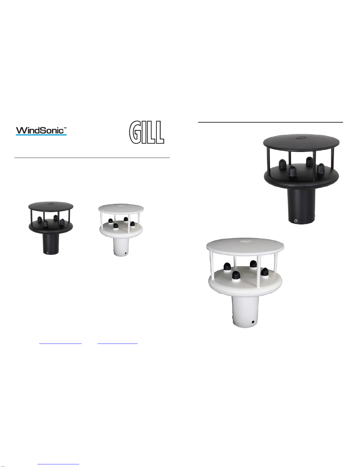
1405-PK-021 Black WindSonic Option 1 – RS 232 output only
1405-PK-068 White WindSonic Option 1 – RS 232 output only
1405-PK-038 Black WindSonic Option 2 – RS 232, 422 & 485 (point to point) output
1405-PK-072 White WindSonic Option 2 – RS 232, 422 & 485 (point to point) output
1405-PK-040 Black WindSonic Option 3 – RS 232, 422, 485 p to p & analogue output
1405-PK-073 White WindSonic Option 3 – RS 232, 422, 485 p to p & analogue output
1405-PK-100 Black WindSonic Option 4 – SDI-12 output only
1405-PK-110 White WindSonic Option 4 – SDI-12 output only
1405-PK-400 Black WindSonic 75 Option 1- RS232 output only
1405-PK-420 Black WindSonic 75 Option 2 RS 232, 422 & 485 (point to point) output
1405-PK-423 Black WindSonic 75 Option 3 RS 232, 422 & 485 p to p & analogue op.
Optional extras:
Item Part No
Cable 4 Pair, twisted and shielded 24 AWG 026-03156
Cable 3 Pair, twisted and shielded 24AWG
Cable 15 metres (4 pair twisted and shielded 24AWG – Connector
pins attached to one end and stripped wires the other).
WindSonic connector (1 supplied as standard see above)
WindSonic Support Tube 0.5 metre (Aluminium)
026-02660
1405-10-080
1405-PK-069
1405-30-056
Bracket for mounting to a Pole, includes a WindSonic Adaptor 1771-PK-115
WindSonic Doc No 1405 PS 0019 Issue 25 February 2017
11
6.2Packaging
Whilst the WindSonic is being moved to its installation site, the unit should be kept in its
inner packaging. All the packaging should be retained for use if the unit has to be returned at
any time, or if a self-test is performed.
6.3Installation requirements
Host system - One of the following:
PC fitted with a suitable interface to match the chosen communication format
(RS232, RS422, or RS485 (point to point), compatible with the WindSonic option
selected,
and a suitable Terminal Emulation software package. For example HyperTerminal for
Windows or Wind Software that is available from the Gill website at
http://gillinstruments.com/main/software.html.
Gill WindDisplay (WindSonic option 2 or 3 only).
Other equipment with input/output compatibility to the WindSonic Option selected.
For example, Data loggers.
Cable - To connect between the WindSonic and the host system
See Section 7.3.1 Cable type for cable specification.
There are restrictions on the maximum cable lengths for correct operation.
The cable should be routed up the inside of the mounting tube.
Mounting tube (e.g. 0.5 metre long Gill part 1405-30-056)
Standard tube 1.75 inches (44.45mm) Outside Diameter x 3mm wall thickness. Note it is
important that the correct diameter tube is usedto prevent damage to the
WindSonic lower moulding when tightening the screws.
See Figure 3, Alignment & Mounting Details on page 26.
For non-hostile environments, Aluminium tube can be used.
For hostile environments, you should select a material suitable for the intended
environment. For example, stainless steel 316 for marine use.
Mounting Bracket (Gill Part 1771-PK-115)

WindSonic Doc No 1405 PS 0019 Issue 25 February 2017
12
6.4Cable Assembly
Open the pack of parts provided with the WindSonic or as 1405-PK-069
Trim back the screened cable outer and screen sleeves 40mm.
Trim back the screen drain wires flush with the outer sleeve.
Strip back the connection wires by 5mm and tin solder.
Solder the contact pins to the wires (please note that the connector supplies the correct strain
relief for cables with an outside diameter of 6-12mm).
Put the parts on the cable in the order as shown below.
Whilst squeezing the red retainer in the direction of ARROWS A, pull in the direction of
ARROW B. A A
B
Your connector should now resemble the connector in the picture below.
Screen Twisted Pair Cable
5 mm
40 mm
Screen drain wires cut flush
WindSonic Doc No 1405 PS 0019 Issue 25 February 2017
13
Insert each contact pin until you feel a slight click. If you have inserted the contact into the
incorrect hole it can be removed at this point by simply pulling it out. Please note there will
be some resistance.
Rear View of Connector
1
9
5
3
7
4
2
6
8

WindSonic Doc No 1405 PS 0019 Issue 25 February 2017
14
Continue to insert all of the contacts you require. Once all of the contacts are inserted push
the red retainer into place. NB. The retainer can only be pushed back into place if the
contacts are fully engaged.
Fit the connector to the WindSonic so that you can finish assembling the connector.
Screw the back shell onto the connector until it is fully in place. Please note that the final
rotations can be slightly stiff.
WindSonic Doc No 1405 PS 0019 Issue 25 February 2017
15
Now screw the next part of the connector into place.
Now screw the cable-clamping nut into place.
The connector can now be removed from the WindSonic.
NOTE: To disassemble the connector, reverse this procedure.
For spares purposes the complete WindSonic Souriau Clipper connector comprises of:-
9 way Connector CLF1201.
Connector female contact CM10SS10MQ.
Sealing Gland Clipper size1 CL101021 (suitable for cables 6-12mm outer diameter).

WindSonic Doc No 1405 PS 0019 Issue 25 February 2017
16
7 INSTALLATION
Do NOT remove the black “rubber” transducer caps. Warranty is void if the coloured
security seal is damaged or removed.
7.1Installation Guidelines
The WindSonic has been designed to meet and exceed the stringent standards listed in its
specification. Operating in diverse environments all over the world, WindSonic requires no
calibration and adjustment whatsoever.
As with any sophisticated electronics, good engineering practice should be followed to
ensure correct operation.
Always check the installation to ensure the WindSonic is not affected by other
equipment operating locally, which may not conform to current standards, e.g.
radio/radar transmitters, boat engines, generators etc.
Guidelines –
oAvoid mounting in the plane of any radar scanner – a vertical separation
of at least 2m should be achieved.
oRadio transmitting antennas, the following minimum separations (all
round) are suggested
VHF IMM – 1m
MF/HF – 5m
Satcom – 5m (avoid likely lines of sight)
Use cables recommended by Gill. If cables are cut and re-connected incorrectly
(perhaps in a junction box) then EMC performance may be compromised if cable
screen integrity is not maintained.
Earth loops should not be created – wire the system in accordance with the
installation guidelines.
Ensure the power supply operates to the WindSonic specification at all times.
Avoid turbulence caused by surrounding structures that will affect the accuracy of the
WindSonic such as trees, masts and buildings. Ideally sensors should be mounted on the
prevailing wind side of the site.
The WMO make the following recommendations:
The standard exposure of wind instruments over level open terrain is 10m above the
ground. Open terrain is defined as an area where the distance between the sensor and
any obstruction is at least 10 times the height of the obstruction.
If mounting on a building then theoretically the sensor should be mounted at a height of 1.5
times the height of the building.
If the sensor is to be mounted on a mast boom, part way up a tower or mast, then the boom
should be at least twice as long as the minimum diameter or diagonal of the tower. The
boom should be positioned on the prevailing wind side of the tower.
WindSonic Doc No 1405 PS 0019 Issue 25 February 2017
17
7.2Bench system test
Note: Prior to physically mounting the WindSonic in its final location, we
strongly recommend that a bench system test is carried out to confirm the
system is configured correctly, is fully functional and electrically
compatible with the selected host system and cabling (preferably utilising
the final cable length). The required data format, units, output rate, and
other options should also all be set up at this stage.
7.3Electrical
7.3.1 Cable
Cable type
A RS422 compatible cable should be used, with the number of twisted pairs matching the
application.
Generic description – Twisted pairs with drain wire, screened with aluminised tape,
with an overall PVC sheath of 6mm-12mm outer diameter. Wire size 7/0.2mm (24 AWG).
The table shows some suitable manufacturers’ references; other manufacturers’ equivalents
can be used.
Application No. of pairs Gill ref.
24 AWG
Belden ref.
24 AWG
Batt
electronics
ref.
24 AWG
WindDisplay 2 - 9729 -
RS 232 3 026-02660 9730 91030
RS 422 4 026-03156 9728 91199

WindSonic Doc No 1405 PS 0019 Issue 25 February 2017
18
Cable length
The maximum cable length is dependent on the chosen communication format (RS232,
RS422 or RS485 (point to point), the baud rate, and, to a lesser extent, on the cable type and
the local electrical ‘noise’ level.
The table shows the typical maximum lengths at the given baud rates, using the
recommended cable. If any problems of data corruption etc. are experienced, then a slower
baud rate should be used. Alternatively, a thicker or higher specification cable can be tried.
WindSonic
Option Communication format Baud rate Max. cable length
Option 1, 2 and 3 RS232 9600 6.5 m (20 ft)
Option 2 and 3 RS422 or RS485 point to
point 9600 1 km (3200 ft)
Option 3
Analogue – Voltage o/p N/A 6.5 m (20 ft)
Analogue – Current o/p
N/A
Resistance dependent
(max 300 Ω)
7.3.2 Power supply
WindSonic Option 1 and 2 Units; Require a DC supply of between 5V – 30 V DC (30V DC
max).
WindSonic Option 3 Units; Require a DC supply of between 7V– 30 V DC (30V DC
max).
WindSonic current drain depends on variant i.e. Option 1, RS232 approximately 9mA at 12v
dc rising to 44mA for Analogue variant.
Lowest power consumption is obtained with the following configuration: -
M2, P20, B3, S9 (approximately 5.5mA at 12v).
WindSonic 75 Option 1, 2 and 3 Units; Require a DC supply of between 12V – 30 V
DC (30V DC max).
WindSonic 75 Option 1 and 2 current drain is typically approximately 13mA at 12v dc.
WindSonic Doc No 1405 PS 0019 Issue 25 February 2017
19
7.4Connecting to a PC using RS232 (Option 1 Sensor)
Notes
1. The cable length for reliable operation is limited to 6.5m (20ft).
(See Section 7.3.1 Cable length.)
2. For longer cable runs, we recommend using the WindSonic configured with RS422
output, and a RS422/232 converter at the PC.
3. Wiring connections below are not applicable to WindSonic Options 2 and 3 set for
RS232 operation.
WindSonic
9 Way circular connector Typical PC or RS232 to USB
Converter Serial Port
9 Way ‘D’ Connector
Signal names Pin nos. Cable – 3 twisted
pairs Signal names Pin no's
TXD
RXD
5
7 RXD
TXD
2
3
Signal
Ground 1 Signal Ground 5
Do NOT
connect
at this end
N/A Screen and drain
wires
Chassis
ground N/A
V supply -
V supply +
2
3
–
+
DC Power supply
(See Para 7.3.2)
Default Settings
The WindSonic Option 1 unit is factory configured with the following default settings:
M2, U1, O1, L1, P1, B3, H1, NQ, F1, E3, T1, S4, C2, G0, K50,

WindSonic Doc No 1405 PS 0019 Issue 25 February 2017
20
7.5Connecting WindSonic Option 2 or 3 set for default
RS422 to a PC using an RS232 Safe Mode Connection.
WindSonic
9 Way circular connector PC
Typical 9 Way ‘D’ Connector
Signal names Pin nos. Cable – 3 twisted
pairs Signal names Pin no's
TXD
RXD
5
7 RXD
TXD
2
3
Signal
Ground 1 Signal Ground 5
Do NOT
connect
at this end
N/A Screen and drain
wires
Chassis
ground N/A
V supply +
V supply -
2
3
+
–
DC Power supply
(See Para 7.3.2)
1. Connect the Option 2 or 3 WindSonic as per the above connection diagram.
2. With WindSonic power off, set up a HyperTerminal connection as per Page 46 but
with the Baud rate set to 19200 (this can be at variance with the original
WindSonic Baud rate setting).
3. Hold down the * character (shift 8) and then apply power to the WindSonic. After
approximately 3 seconds the unit will respond with Safe Mode.
4. To change output communication from RS422 to RS232 then remove any * characters
on screen.
5. Type E3 and press Enter (changes E2 setting to E3).
6. E3 will be seen twice on screen to confirm the setting change to RS232 has occurred.
7. Change any other configuration settings as required.
8. Type Q and press Enter to go back into measurement mode (garbled data may appear
on screen if the original WindSonic Baud rate setting is not 19200bauds).
9. If required close the 19200-baud HyperTerminal connection and re-open at the
WindSonic Baud rate. If a continuous data mode has been previously chosen then data will
scroll on screen.
(Note that supply voltage connections are reversed compared to the Option 1 RS232
unit. Damage will not occur from a reverse voltage connection).
7.6Changing an Option 2 or 3 Sensor set for RS232 back
to RS422.
Connect the Option 2 or 3 WindSonic as per Para 7.5.
Repeat instructions shown in Para 7.5 except that in Safe Mode set the E Command to E2
etc.
WindSonic Doc No 1405 PS 0019 Issue 25 February 2017
21
7.7Connecting to a Gill WindDisplay
Meteorological Display Marine Display
The WindSonic is designed to interface with the Gill WindDisplay unit to provide a
complete wind speed and direction system.
To interface to a non NMEA WindDisplay the WindSonic is set by default for Polar
(M2) and 9600 (B3) configuration settings.
When coupled to a WindDisplay, the WindSonic can be used as supplied, however if a
fault occurs the WindDisplay may lock into the last valid reading. Re-configuring the
WindSonic to Fixed Field output (O2) will ensure that any fault is flagged on the
WindDisplay.
After coupling to a WindDisplay, the Wind Speed units and the Averaging period can
be selected using the WindDisplay controls. See the WindDisplay User Manual.
Note that although the WindDisplay can display wind speed in various units, these are
calculated within the WindDisplay. The data coming to the WindDisplay must be in
metres/sec (the factory default output setting).
Notes
1. WindSonic Option 2 or 3 must be used set for RS422 output (E2 Mode).
2. Use the WindSonic in the factory default mode for the Meteorological Wind
Display – i.e. do not reconfigure.
3. If used with a Marine NMEA 9600Baud or4800 Baud WindDisplay set the
Wind Sonic for NMEA (e.g. M5) and 9600 Baud (B3) or4800 Baud (B2).
4. The WindDisplay can provide power to the WindSonic.
WindSonic Connector Cable WindDisplay
Signal name Pin no. 2 twisted pairs Signal name Terminal no.
TXD +
TXD – 4
5 TXD +
TXD – 8
7
No connection N/A Screen and drain
wires Ground (Earth)
V supply +
V supply -
2
3
+
O 2
1

WindSonic Doc No 1405 PS 0019 Issue 25 February 2017
22
7.8Connecting to a PC using RS422 (Option 2 or 3)
WindSonic
9 Way circular connector PC with RS422/232
converter
Signal names Pin nos. Cable – 4 twisted pairs Signal names
TXD+
TXD –
4
5 RXD +
RXD –
RXD+
RXD –
6
7
TXD +
TXD –
Signal Ground 1 Signal Ground
Do NOT connect
at this end N/A Screen and drain wires
Chassis ground
V supply +
V supply -
2
3
+
–
DC Power
supply
(See Para 7.3.2)
Notes
WindSonic to be set for RS422/RS485 mode (E2, default).
Analogue Outputs are also simultaneously available from the Option 3 unit.
Default Settings
The WindSonic Option 2 and 3 unit is factory configured with the following default
settings:
M2, U1, O1, L1, P1, B3, H1, NQ, F1, E2, T1, S4, C2, G0, K50
See Section 10 Configuring for further details
WindSonic Doc No 1405 PS 0019 Issue 25 February 2017
23
7.9Using RS485 (2 wire point to point) with Option 2 or 3
units
Notes
1. The unit must be set for RS422/485 mode (E2 setting).
2. WindSonics must be set in Polled mode, a node address letter may be given if
required.
See Section 9.1 WindSonic node address.
3. Customers may poll using terminal software (NOT supplied).
4. As unit is point to point only it cannot be networked with other RS485 2 wire devices.
WindSonic
9 Way circular connector PC with RS485 card
Signal names Pin
nos. Cable – 3 twisted pairs Signal names
TXD+
RXD+ 4
6 T/RXD +
TXD –
RXD – 5
7 T/RXD –
Signal Ground 1 Signal Ground
Do NOT connect
at this end N/A Screen and drain wires
Chassis ground
V supply +
V supply -
2
3
+
–
DC Power supply
(See Para 7.3.2)
NOTE:
Analogue Outputs are also simultaneously available from the Option 3 unit.

WindSonic Doc No 1405 PS 0019 Issue 25 February 2017
24
7.10 Using the Analogue Output (Option 3)
Notes
1. If the Current output is used, the total output load MUST be below 300 ohms, including
the cable resistance.
2. The current output loads must be returned to Signal Ground.
3. Reconfiguration of the analogue output requires a digital connection (See sections 9 &
10).
4. In addition, the digital output can be connected if required using RS232, 422 or 485
point to point, as shown in the previous sections.
WindSonic
9 Way circular connector Data logger or
Chart recorder
Signal names Pin
nos. Cable – 3 twisted pairs Signal names
Analogue Channel 1
(Speed)
Analogue Channel 2
(Direction)
8
9
Analogue Channel 1
Analogue Channel 2
Signal Ground
(Analogue Return) 1 Signal Ground
Do NOT connect
at this end N/A Screen and drain wires
Chassis ground
V supply +
V supply -
2
3
+
–
DC Power supply
(See Para 7.3.2)
WindSonic Doc No 1405 PS 0019 Issue 25 February 2017
25
8 Mechanical
Before installing, see note at Section 7.2 Bench system test.
8.1Orientation
Normally the WindSonic is mounted on a vertical tube, ensuring a horizontal Measuring
Plane. See Figure 3 Alignment & Mounting details
For indoor use the unit may be mounted with the Measurement Plane set to any required
orientation.
8.1.1 Alignment
The WindSonic should be aligned to point to North, or any other reference direction –for
example, the bow of a boat.
There are two arrows, a coloured rectangle, and an alignment notch to aid alignment.
See Figure 3 Alignment & Mounting Details
Note: It is usually simpler to work first with a compass at ground level and identifya
suitable landmark and its bearing.
8.1.2 Mounting
The support tube requires three 3 equally spaced holes, tapped M5, 7.5mm from the top of
the tube. Pass the cable (fitted with the 9 wayClipper plug) through the tube.
Note: the customer must fit appropriate strain relief to the cable.
Connect the plug by twisting it whilst pushing it gently into the socket on the WindSonic.
When it locates, twist the outer sleeve clockwise to connect and lock the plug.
Fix the WindSonic to the tube using the 3 stainless steel screws provided. (Maximum
mounting screw torque 4 Nm.)
It is the responsibility of the customer to ensure that the WindSonic is mounted in a position
clear of anystructure, which may obstruct the airflow or induce turbulence.
Do NOT mount the WindSonic in close proximity of high-powered radar or radio
transmitters. A site survey may be required if there is any doubt about the strength of
external electrical noise.
The Mounting Bracket (1771-PK-115)
Mount the Sensor on to the bracket mount and if using a Wind Sensor align so that the
Sensor North Marker points to the bracket pole.
Secure the sensor to its mount using screws and washers supplied in the Sensor Box.
Torque screws to a maximum of 4 Nm.
The Bracket uses a clamp suitable for attaching to a vertical pipe with a diameter of 30-
58mm. When mounting the Bracket Sensor, consider the position, orientation and alignment
of the unit. Mount at the top of a Pipe to ensure a clear unobstructed measurement view.
Note that the mounting pipe should first be degreased and when assembling the Bracket
clamp assembly the outer clamp nuts need to be tightened evenly to a torque figure of 3 Nm.
The moving plate part of the clamp needs to be reversed for poles below 38 mm diameter.
Screw an Earth cable minimum of 6mm2to the Bracket chassis using Screw and Terminal
Tag fixings supplied.

WindSonic Doc No 1405 PS 0019 Issue 25 February 2017
26
Gill Instruments 0.5 metre Aluminium support tube can be supplied with drilled and tapped
M5 holes as above, part number 1405-30-056.
Figure 3 Alignment & Mounting details
WindSonic Doc No 1405 PS 0019 Issue 25 February 2017
27
9 MESSAGE FORMATS
On applying power to the WindSonic, it will provide wind measurements in one of the
following formats:
Gill – Polar, Continuous (default format)
Gill - UV, Continuous
Gill – Polar Polled
Gill – UV Polled
NMEA – IIMWV or WIMWV (with NMEA status Codes)
NMEA - IIMWV or WIMWV (with Gill Status Codes)
Tunnel – U Direction, U Speed
Each of these is described below.
Information on how to change the formats and settings follows in Section 10
CONFIGURING.
9.1Gill format– Polar, Continuous (Default format)
Where:
<STX> = Start of string character (ASCII value 2)
WindSonic node address = Unit identifier
Wind direction = Wind Direction
Wind speed = Wind Speed
Units = Units of measure (knots, m/s etc.)
Status = Anemometer status code (see Section 11.5
for further details)
<ETX> = End of string character (ASCII value 3)
Checksum = This is the EXCLUSIVE – OR of the bytes
between (and not including) the <STX>
and <ETX> characters.
<CR> ASCII character
<LF> ASCII character
<STX>Q, 229, 002.74, M, 00,
<ETX>
16
WindSonic
Node address Wind
direction Wind
speed
Units
Status
Check
sum

WindSonic Doc No 1405 PS 0019 Issue 25 February 2017
28
WindSonic node address
The default setting is ‘Q’. If required the WindSonic M can be configured to show a
different alphabetical node letter (A to Z), so as to identify the WindSonic M.
It is recommended that ID’s A to F and K, M, N and P are not used, as these characters can
be present in the data string.
Wind direction
Indicated in degrees, from 0 to 359, with respect to the WindSonic North marker.
Whilst the wind speed is below 0.05 metres/sec (K50), then in Comma Separated Variable
mode no direction value will be output (e.g. Q,,000.03,M,00,1C). In Fixed Field mode wind
direction output will freeze at the last known valid direction value (e.g. Q,133,
000.02,M,00,1A) until a new valid value can be calculated.
Wind speed and units
Shows the Wind Speed in the Measurement Plane (See Figure 3 Alignment & Mounting
details) in one of the following units:
Units
Identifier
Metres per second (default)
M
Knots
N
Miles per hou
r
P
Kilometres per hour
K
Feet per minute
F
Low Wind Speeds (below 0.05ms)
Whilst the wind speed is below 0.05 metres/sec, the wind direction will not be calculated.
In CSV mode no direction value will be output (e.g. Q,,000.03,M,00,1C). In Fixed Field
mode wind direction output will freeze at the last known valid direction value (e.g. Q,133,
000.02,M,00,1A) until a new valid value can be calculated.
The above applies with the K command set for K50. If K for instance is set for 100 then the
above applies at 0.1m/s.
N
S
W
E
With Wind N to S
Sensor reads
0/360
With Wind E to W
Sensor reads
90
With Wind W to E
Sensor reads
270
With Wind S to N
Sensor reads
180
WindSonic Doc No 1405 PS 0019 Issue 25 February 2017
29
Status
This indicates either
Correct operation Code 00 and A (NMEA).
or Error codes See Section 11.5 for explanation of codes.
Checksum
This enables the host system to check that the data has been correctly received. This is the
EXCLUSIVE – OR of the bytes between (and not including) the <STX> and <ETX>
characters.
Output rate (not displayed)
The WindSonic samples continuously and delivers wind information at ¼, ½, 1 (default
setting), 2, or 4 outputs / second.

WindSonic Doc No 1405 PS 0019 Issue 25 February 2017
30
9.2Gill format – UV, Continuous
In this mode, the output is given as signed (i.e. positive or negative) speeds along the
‘U’ (= South – North) axis and the ‘V’ (= East – West) axis.
Where:
<STX> = Start of string character (ASCII value 2)
WindSonic node address = Unit identifier
U axis = speed & polarity
V axis = speed & polarity
Units = Units of measure (knots, m/s etc.)
Status = Anemometer status code (see Section 11.5
for further details)
<ETX> = End of string character (ASCII value 3)
Checksum = This is the EXCLUSIVE – OR of the bytes
between (and not including) the <STX>
and <ETX> characters
The WindSonic unit identifier, Units, and Checksum are as described in Section 0 above.
Figure 5 shows the polarity of U and V if the wind components along the U and V axis are
blowing in the direction of the respective arrows.
Figure 5 UV Polarity
<STX>Q, +001.59,
-
002.74, M, 00, <ETX> 2D
WindSonic
node
address
U axis
speed and
polarity
V axis
speed and
polarity
Units
Status
Check
sum
WindSonic Doc No 1405 PS 0019 Issue 25 February 2017
31
9.3Gill format – Polled (Polar or UV)
When in the Polled mode, an output is only generated when the host system sends a Poll
signal to the WindSonic consisting of the WindSonic Unit Identifier – that is, the relevant
letter A – Z.
The output formats are otherwise as described in Sections 9.1 and 9.2.
The commands available in this mode are:
Description Command WindSonic response
WindSonic Unit Identifier A ….. Z Wind speed output generated
Enable Polled mode ? (None)
Disable Polled mode ! (None)
Request WindSonic Unit Identifier ? & A ….. Z (as configured)
Enter Configuration mode *<N> CONFIGURATION MODE
Where <N> is the unit identifier, it is recommended that ID’s A to F and KMNP are not used
as these characters can be present in the data string.
Notes: -
It is suggested that in polled mode the following sequence is used for every poll for
information.
? Ensures that the Sensor is enabled to cover the event that a power down has occurred.
A-Z Appropriate unit designator sent to retrieve a line of data.
! Sent to disable poll mode and reduce possibility of erroneous poll generation.
When in polled mode the system will respond to the data command within 130mS with the
last valid data sample as calculated by the Output rate (P Mode Setting).
If the unit is powered down after use or upon switch on then allow 5 seconds from switch on
before sending poll commands.
Polled mode can only be used for point to point communications. It is not possible to
network units on a common bus.

WindSonic Doc No 1405 PS 0019 Issue 25 February 2017
32
9.4NMEA Format (NMEA status Codes)
The Wind Direction, Wind Speed, and Units are as described in Section 9.1.
The Instrument Type – IIMWV - is a mnemonic for Integrated Instrument Mean Wind
direction & Velocity.
The Status codes are:
A Acceptable measurement
V Void measurement
A typical WindSonic configuration suitable for NMEA (See Section 10):
M5, U1, O1, L1, P1, B2, H1, NQ, F1, E2, T1, S4, C2, G0, K50
Consult specification NMEA 0183 version 3 (available on the web) for complete interface
details.
The WindSonic can also be set for the alternative start of string NMEA format WIMWV
(Mode 14, which is a Mnemonic for: -
Wind Instrument Mean Wind direction and Velocity.
The string format will appear as above but with WIMWV at the start of the string.
$ IIMWV, 120, R, 002.10, M, A*5D
Wind direction
Wind speed
Units
Status
Start of
string Instrument
type
Relative wind measurement
Check sum
WindSonic Doc No 1405 PS 0019 Issue 25 February 2017
33
9.5NMEA Format (Gill status Codes)
The Wind Direction, Wind Speed, and Units are as described in Section 9.1.
The Instrument Type – IIMWV - is a mnemonic for Integrated Instrument Mean Wind
direction & Velocity (alternative start of string format WIMWV can be selected).
The Gill Status codes are as described in Para 11.5.
A typical WindSonic configuration suitable for NMEA (See Section 10):
M16, U1, O1, L1, P1, B3, H1, NQ, F1, E2, T1, S4, C2, G0, K50
Consult specification NMEA 0183 version 3 (available on the web) for complete interface
details.
9.6Gill format – Tunnel Mode (UU, Continuous)
In this mode, the output is given as a signed figure (i.e. positive or negative) along the
‘U’ (= South – North) axis.
Direction is indicated by a 0 or 1.
Where:
<STX> = Start of string character (ASCII value 2)
WindSonic node address = Unit identifier
U axis = U axis Wind Speed
U axis U axis Wind Direction Polarity where: -
0 (–U vector) is a wind from the North direction or
1 (+U vector) is a wind from the South direction.
See Section 9.1 for other string information.
$ IIMWV, 120, R, 002.10, M, 00*5D
Wind direction
Wind speed
Units
Status
Start of
string Instrument
type
Relative wind measurement
Check sum
STX> Q, 001.59, 1, 00, M, <ETX> 2D
WindSonic
node
address
U axis
speed
U axis
polarity
Status
Units
Check
sum

WindSonic Doc No 1405 PS 0019 Issue 25 February 2017
34
9.7Analogue Outputs and Options
Notes: Analogue outputs are only available from WindSonic Option 3.
Analogue Wind Speed output is in Metres/Second only.
9.7.1 Voltage or Current output
The WindSonic (Option 3) can be configured for either Voltage (0 – 5 V) or Current (0 –
20mA and 4 – 20 mA) outputs.
Important:
1. When using the current outputs, the load resistance between the Analogue outputs (Pins
8 & 9) and Signal Ground (Pin 1) must be <= 300 ohms, including cable resistance.
This is to ensure that the voltage levels on Pins 8 & 9 do not exceed 5V.
2. The current outputs must be returned to Signal Ground (Pin 1).
9.7.2 Analogue Output Modes
Analogue
Outputs
Polar Mode
Modes 2 and 4
NMEA Mode
Modes 5,14,15
&16
UV Mode
Modes 1 and 3
Tunnel Mode
Mode 12
Channel 1
(Pin 8 wrt Pin 1)
Wind Speed
Wind Speed
U
Wind Speed
U Wind Speed
Channel 2
(Pin 9 wrt Pin 1)
Wind Direction
Wind Direction
U Wind Polarity
U Wind Polarity
9.7.3 Polar mode direction wraparound
The Wind Direction in Polar mode can be configured for either Standard (0 - 359) or
Wraparound (0 - 539) options. If the Standard mode is used with a chart recorder, large
swings of the recorder pen will be experienced each time the wind direction passes between
0 and 359. Using the Wraparound mode, when the wind first changes from 0to 359, there
will be a step change on the output, but after this first time the output will change smoothly
each time the wind passes through 360. (Similarly, the first time the wind veers from 539
to 180; there will be a step change, after which the output will change smoothly).
Wind
Direction
(degrees)
Voltage Output
(0v to 5V)
Current Output
(0mA to 20mA)
Current Output
(4mA to 20mA)
Standard
Wraparound
Standard
Wraparound
Standard
Wraparound
0
0
0
0.00
0.00
4.00
4.00
180
2.5
1.67
10.00
6.67
12.00
9.33
360
5.0
3.
33
20.00
13.33
20.00
14.67
540
N/a
5.0
N/a
20.00
N/a
20.00
WindSonic Doc No 1405 PS 0019 Issue 25 February 2017
35
9.7.4 Wind Speed scaling
Analogue Outputs are always scaled in m/s irrespective of the digital output units of
measurement setting.
The Wind Speed output can be configured such that full-scale output represents 5, 10, 20,
30, 40, 50 or 60 metres/sec.
In all cases zero Wind Speed is represented by 0V, 0mA or 4mA.
9.7.5 Tunnel mode
When configured in Tunnel mode, Channel 1 output represents the wind speed along the U
axis (South – North) scaled as described above.
Channel 2 gives the direction of the wind along the U axis, where a –U vector (= wind from
the N direction) is represented by0V (or 0mA, 4mA), and a +U vector is represented by 5V
(or 20mA).
9.7.6 Analogue Output Rate
In Continuous and Polled modes the analogue output update rate will be determined by the P
command setting.
9.7.7 Disabled outputs
If the analogue outputs are not required, they can be disabled (Command S9).
9.7.8 Analogue Output Conditions
Analogue signals are output together with Digital Outputs signals.
Analogue signals are output continuously when in Digital Polled Mode.
Note: - The WindSonic provides the power for current output loads. Do not connect the
WindSonic output to instruments where power for the current loop is provided by the
instrument connecting to the WindSonic current output connections.

WindSonic Doc No 1405 PS 0019 Issue 25 February 2017
36
9.7.9 Low wind speeds (below 0.05 m/s).
Whilst the wind speed is below 0.05 metres/sec, the wind direction will not be calculated.
In both CSV mode and in Fixed Field mode, Channel 2 wind direction output will freeze at
the last known valid direction value until a new valid value can be calculated.
The above applies with the K command set for K50. If K for instance is set for 100 then the
above applies at 0.1m/s.
Wind Speed Condition
Channel 1 Spee
d Output
Channel 2 Direction Output
Greater Than 0.05m/s
0
-
5v, 0/
4
–
20mA variable
0
-
5v, 0/
4
–
20mA variable
Less Than 0.05m/s
0
-
5v, 0/
4
–
20mA variable
Hold last known good
reading above 0.05m/s
speed until wind speed
increases above 0.05m/s
9.7.10 Error condition reporting
In both CSV and Fixed Field Modes, if a valid wind measurement cannot be calculated due
to a fault condition (for example all paths blocked), the Analogue outputs on Channels 1 and
2 can report a digital error status condition depending on the Y command setting.
NOTE: TheY command is not applicable to WindSonic 75 Analogue output units.
WindSonic 75 units will report Error conditions as though set for Y1 below.
Y1 setting (Default).
Under data error conditions will switch back and forth between 0 and 5V (or 0/4 to 20mA) at
the selected output rate.
The following table summarises the above reporting conditions with Analogue Outputs set
for Polar Continuous Output and 0-5v (T1), 0-20mA (T5) and 4-20mA (T3).
Wind Speed Condition
Channel 1
Speed
Channel 2 Direction
Digital Error Code
Output e.g. 01, 02, 04
etc.
Cycle 0 – 5 – 0 v
at output rate Cycle 0 – 5 – 0 v
at output rate
Cycle 0 – 20 – 0 mA
at output rate Cycle 0 – 20 – 0 mA
at output rate
Cycle 4 – 20 – 4 mA at
output rate Cycle 4 – 20 – 4 mA at
output rate
WindSonic Doc No 1405 PS 0019 Issue 25 February 2017
37
Y2 nnn Setting, User Set Fixed Analogue Output level in an error mode.
The unit will output a fixed Voltage (T1 setting) or fixed milli-amp (T5/T3 settings) signal
on the analogue output with a value depending on the Y2 nnn setting.
nnn is user-selectable value between 000 to 200.
Scale factor for fixed voltage output is 0.025V.
Scale factor for fixed current output is 0.1mA.
Therefore:-
nnn value = Required fixed Error Voltage/0.025 (voltage output setting T1).
nnn value = Required fixed Error Current/0.1 (current output settings T5/T3).
Under data error conditions then by setting the unit for Y2 configuration the analogue
outputs will read a user set error value for the period of the error condition as follows with
the unit in Polar Continuous Output and 0-5v (T1), 0-20mA (T5) and 4-20mA (T3).
Wind Speed
Condition
Channel 1 Speed
Channel 2 Direction
Digital Error
Code Output
e.g. 01, 02, 04 etc
Error Condition
nnn x 0.025 v (T1 setting). Error Condition
nnn x 0.025 v (T1 setting).
Error Condition
nnn x 0.1mA. (T5 & T3 setting) Error Condition
nnn x 0.1mA. (T5 & T3 setting)
Y3 nnn setting Analogue Output cycles to a user determined level in an error mode.
Under data error conditions the analogue outputs will switch back and forth between a user
determined level (voltage or current) with a value depending on the Y3 nnn setting.
nnn is user-selectable value between 000 to 200.
Scale factor for upper voltage output is 0.025V.
Scale factor for fixed current output is 0.1mA.
Therefore:-
nnn value = Required Error Voltage/0.025 (voltage output setting T1).
nnn value = Required Error Current/0.1 (current output settings T5/T3).
The following table summarises the above reporting conditions with Analogue Outputs set
for Polar Continuous Output and 0-5v (T1), 0-20mA (T5) and 4-20mA (T3).
Wind Speed Condition
Channel 1 Speed
Cha
nnel 2 Direction
Digital Error Code
Output e.g. 01, 02, 04
etc.
Cycle 0 – set v – 0 v
at output rate Cycle 0 – set v – 0 v
at output rate
Cycle 0 – set mA – 0 mA
at output rate Cycle 0 – set mA – 0 mA
at output rate
Cycle 4 – set mA – 4 mA
at output rate Cycle 4 – set mA – 4 mA
at output rate

WindSonic Doc No 1405 PS 0019 Issue 25 February 2017
38
ERROR CONDITION REPORTING NOTES:
1. Y1, Y2 and Y3 settings are implemented in firmware version 2368-110-01 and
onwards.
2. The Y command is not reported in the D3 string, a Terminal Program is used to set
up the Y Command.
3. When setting Y2 or Y3 level note that there is a space character after Y2 or Y3 and
before the nnn value e.g. Y2 150.
For instance if the unit is set for 0-5v analogue outputs and it is required to report a
fixed voltage level of 3.75v under error conditions (Y2 150) then:-
Open a terminal program (e.g. HyperTerminal, Tera Term or Gill Wind Software
(Wind Wizard not applicable)) at the matching COM Port connection and Baud
rate.
Type * to place the unit into CONFIGURATION MODE.
Type Y2 150 and press the Enter key.
Type Q and press Enter to return to Measurement Mode.
4. To check the Y settings then in Configuration Mode Type Y and press the Enter
key and the unit will report Y1 or the full Y2 or Y3 setting e.g.
Y
Y2 0 (=Y2 000)
Y
Y2 1 (=Y2 001)
Y
Y2 10 (=Y2 010)
Y
Y2 100 (=Y2 100)
WindSonic Doc No 1405 PS 0019 Issue 25 February 2017
39
10 CONFIGURING
Gill Wind Software may be used to configure the WindSonic; alternatively, the user may
elect to use another terminal emulator package such as Windows HyperTerminal. This
section describes the commands used to change User and Communications settings.
10.1 Wind
Wind software is available on the supplied CD or to download, free of charge, from the Gill
Instruments Limited website http://gillinstruments.com/main/software.html .
Wind software allows the unit configuration to be changed and to be able to display the
Digital Data String on a PC screen.
NOTE: Wind is not compatible with WindSonic Option 4 – SDI-12 or WindSonic units
prior to serial number 08100001 with a yellow or blue tab adjacent to the North Marker.
Connect both WindSonic transmit and receive data lines to the PC to establish 2 way
communications.
Open Wind Software and select the appropriate Com Port from the drop down menu and
click on OK to reach the data screen.
If data is not correctly displayed then on the Menu click on Tools/Synch Comms.
The Sensor will be interrogated and Sensor Baud Rate and Mode settings detected and
reported.
Wind software settings will be adjusted to match those of the sensor to show data scrolling
on screen.
If after Synch Comms there is still a problem, repeat Synch Comms or switch off the sensor
and switch back on again and repeat above procedure.
Note: - It is also possible to use Wind as a TerminalProgram and change settings using
the Configuration Mode of operation (Commands are listed in Para’s 10.4 to 10.7.1).
Table of contents
Popular Accessories manuals by other brands

O’Dive
O’Dive ONE user manual

Ankom
Ankom Daisy D200 Replacement

Sportcraft
Sportcraft 92723-SR Assembly instructions

S+S Regeltechnik
S+S Regeltechnik Aerasgard KCO2 Series Operating Instructions, Mounting & Installation

Saramonic
Saramonic SmartRig plus Di user manual

Brinsea
Brinsea Ovation 28 Advance operating manual