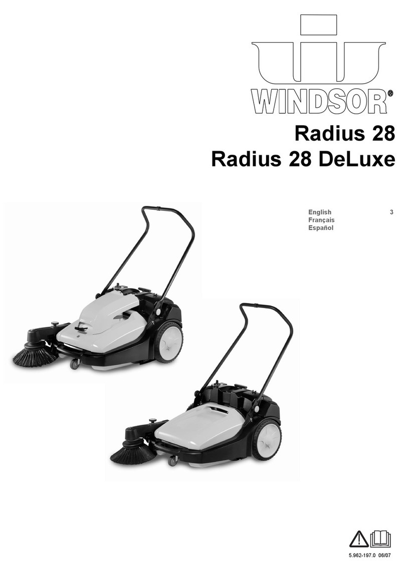
Windsor TRACER FS User manual

MODEL: TRACER FS (Battery Version)
Operating Instructions
98351 11/01/03
F
FLOOR SWEEPER
Read these instructions before using the machine

MACHINE DATA LOG
QTFSB 98351 04/25/03
2
For the name and address of your dealer contact: Windsor Industries
YOUR DEALER
Name: __________________________________________________________________________________________________
Address: _______________________________________________________________________________________________
Phone Number: _________________________________________________________________________________________
MODEL _______________________________________
DATE OF PURCHASE __________________________
SERIAL NUMBER ______________________________
SALES REPRESENTATIVE # _____________________
DEALER NAME ________________________________
OPERATIONS GUIDE NUMBER ___________________
PUBLISHED __________________________________________
Copyright 1995 Windsor Industries, Printed in USA

TABLE OF CONTENTS
QTFSB 98351 04/25/03
3
Machine Data Log..........................................2
Table of Contents...........................................3
HOW TO USE THIS MANUAL
How to use this Manual..................................1-1
SAFETY
Important Safety Instructions.........................2-1
Hazard Intensity Level...................................2-2
Safety Label Location.....................................2-3
OPERATIONS
Technical Specifications..............................3-1
Controls........................................................3-2
Machine Operation.......................................3-7
Pre-Run Machine Inspection....................3-7
Starting Machine.......................................3-7
Sweeping...................................................3-7
Operating on Grades ................................3-8
Stopping Machine.....................................3-8
Storing Machine........................................3-8
Towing Machine........................................3-9
Machine Jacking.......................................3-9
Machine Tie-Downs..................................3-9
Dumping Hopper.......................................3-10
Hopper Safety Arm...................................3-10
MAINTENANCE
Battery Information.......................................4-1
Hydraulics ....................................................4-3
Directional Control System..........................4-5
Throttle “Neutral Position”............................4-6
Main Broom..................................................4-7
Side Broom ..................................................4-9
Belts .............................................................4-11
Drive Wheel Chain.......................................4-12
Skirts............................................................4-13
Hopper..........................................................4-14
Brakes/Tires.................................................4-16
Hydraulic Schematic....................................4-17
Hydraulic Troubleshooting...........................4-17
Propelling Troubleshooting..........................4-18
Machine Troubleshooting.............................4-19
Service Schedule.........................................4-20
GROUP PARTS LIST
Frame Group................................................5-1
Differential Group.........................................5-3
Front Wheel Drive Group.............................5-5
Auxiliary Drive Group...................................5-7
Impeller Group.............................................5-9
Impeller (Wet Sweep Bypass) Group..........5-11
Rear Clip Group...........................................5-13
Console Group.............................................5-15
Brake Group.................................................5-17
Steering Group.............................................5-19
Rear Suspension Group..............................5-21
Electrical Group...........................................5-23
Safety Switch Group....................................5-25
Side Broom Group.......................................5-27
Filter Group..................................................5-29
Hydraulic Group...........................................5-31
Hopper Group..............................................5-31
Main Broom Lift Group.................................5-35
Main Broom Group.......................................5-37
Instrument Panel Group...............................5-39
Wiring Group................................................5-41
Cable Routing Sheet #1...............................5-43
Main Harness...............................................5-44
Throttle Harness..........................................5-45
Rear Clip Harness.......................................5-46
Hopper Harness...........................................5-47
Cable Routing Harness #2...........................5-48
Notes............................................................5-49
Warranty ......................................................5-50

HOW TO USE THIS MANUAL
QTFSB 98351 04/25/03
1-1
This manual contains the following sections:
-HOW TO USE THIS MANUAL
-SAFETY
-OPERATIONS
-MAINTENANCE
-PARTS LIST
The HOW TO USE THIS MANUAL section will tell
you how to find important information for ordering
correct repair parts.
Parts may be ordered from authorized Windsor
dealers. When placing an order for parts, the
machine model and machine serial number are
important. Refer to the MACHINE DATA box which
is filled out during the installation of your machine.
The MACHINE DATA box is located on the inside of
the front cover of this manual.
The model and serial number of your machine is on
the bottom back-end of the machine.
The SAFETY section contains important information
regarding hazard or unsafe practices of the
machine. Levels of hazards is identified that could
result in product or personal injury, or severe injury
resulting in death.
The OPERATIONS section is to familiarize the
operator with the operation and function of the
machine.
The MAINTENANCE section contains preventive
maintenance to keep the machine and its
components in good working condition. They are
listed in this general order:
-Batteries
-Hydraulics
-Directional Control
-Main Broom
-Side Broom
-Belts
-Skirts
-Hopper
-Hydraulic Schematic/Troubleshooting
-Service Schedule
-Machine Troubleshooting
-Electrical Schematic
The PARTS LIST section contains assembled parts
illustrations and corresponding parts list. The parts
lists include a number of columns of information:
-REF – column refers to the reference
number on the parts illustration.
-PART NO. – column lists the part
number for the part.
-QTY – column lists the quantity of the
part used in that area of the machine.
-DESCRIPTION – column is a brief
description of the part.
-SERIAL NO. FROM – column indicates
the first machine the part number is
applicable to. When the machine design
has changed, this column will indicate
serial number of applicable machine.
The main illustration shows the most
current design of the machine. The
boxed illustrations show older designs. If
column has an asterisk (*), call
manufacturer for serial number.
-NOTES – column for information not
noted by the other columns.
NOTE: If a service or option kit is installed on your
machine, be sure to keep the KIT INSTRUCTIONS
which came with the kit. It contains replacement
parts numbers needed for ordering future parts.
NOTE: The 98# on the lower left corner of the front
cover is the part number for this manual.
MODEL _____________________________________
DATE OF PURCHASE ________________________
SERIAL NUMBER ____________________________
SALES REPRESENTATIVE # ___________________
DEALER NAME ______________________________
OPERATIONS GUIDE NUMBER __________________
PUBLISHED ________________________________
Copyright1995WindsorIndustries,PrintedinUSA

QTFSB 98351 04/25/03
2-1
IMPORTANT SAFETY INSTRUCTIONS
When using an battery powered appliance, basic precaution
must always be followed, including the following:
READ ALL INSTRUCTIONS BEFORE USING THIS MACHINE.
To reduce the risk of fire, electric shock, or injury:
Use only indoors. Do not use outdoors or expose to rain.
Use only as described in this manual. Use only manufacturer’s recommended components and
attachments.
If the machine is not working properly, has been dropped, damaged, left outdoors, or dropped into
water, return it to an authorized service center.
Do not operate the machine with any openings blocked. Keep openings free of debris that may reduce
airflow.
This machine is not suitable for picking up hazardous dust.
Machine can cause a fire when operating near flammable vapors or materials. Do not operate this
machine near flammable fluids, dust or vapors.
This machine is suitable for commercial use, for example in hotels, schools, hospitals,
factories, shops and offices for more than normal housekeeping purposes.
Maintenance and repairs must be done by qualified personnel.
If foam or liquid comes out of machine, switch off immediately.
Disconnect battery before cleaning or servicing.
Before the machine is discarded, the batteries must be removed and properly disposed of.
Make sure all warning and caution labelsare legible and properly attached to the machine.
During operation, attention shall be paid to other persons, especially children.
Before use all covers and doors shall be put in the positions specified in the instructions.
When leaving unattended, secure against unintentional movement.
The machine shall only be operated by instructed and authorized persons.
When leaving unattended, switch off or lock the main power switch to prevent unauthorized use.
Only chemicals recommended by the manufacturer shall be used.
This appliance has been designedfor use with the brushes specified by the manufacturer. The fitting
of other brushes may affect its safety.
SAVE THESE INSTRUCTIONS
!
WARNING:

HAZARD INTENSITY LEVEL
QTFSB 98351 04/25/03
2-2
The following symbols are used throughout this guide as indicated in their descriptions:
HAZARD INTENSITY LEVEL
There are three levels of hazard intensity identified by signal words -WARNING and CAUTION and FOR
SAFETY . The level of hazard intensity is determined by the following definitions:
WARNING - Hazards or unsafe practices which COULD result in severe personal injury or death.
CAUTION - Hazards or unsafe practices which could result in minor personal injury or product or property
damage.
FOR SAFETY: To identify actions which must be followed for safe operation or equipment.
Report machine damage or faulty operation immediately. Do not use the machine if it is not in proper
operating condition. Following is information that signals some potentially dangerous conditions to the
operator or the equipment. Read this information carefully. Know when these conditions can exist. Locate
all safety devices on the machine. Please take the necessary steps to train the machine operating
personnel.
FOR SAFETY
DO NOT OPERATE MACHINE:
Unless Trained and Authorized.
Unless Operation Guide is Read and understood.
In Flammable or Explosive areas.
In areas with possible falling objects.
WHEN SERVICING MACHINE:
Avoid moving parts. Do not wear loose clothing; jackets, shirts, or sleeves when working on the
machine. Use Windsor approved replacement parts.
Batteries emit hydrogen gas. Explosion or fire can result. Keep sparks and open flame away. Keep
solution tank in raised position when charging. Keep sparks and flames away from the batteries.
Do not smoke around batteries.
Disconnect batteries before working on machine. Only qualified personnel should work inside
machine. Always wear eye protection and protective clothing when working on or near batteries.
Avoid skin contact with the acid contained in the batteries.
Never allow metal to lie across battery tops.
!
WARNING
!
WARNING
!
WARNING
!WARNING
!CAUTION

SAFETY LABEL LOCATION
QTFSB 98351 04/25/03 2-3
NOTE: These drawings indicate the location of safety labels on the Tracer FS.If, at any time, the labels become
illegible contact your Windsor representative for prompt replacement.
BATTERY CAUTION 80885
(Located on seat backing plate)
FAN BELT WARNING 80811

SAFETY LABEL LOCATION
QTFSB 98351 04/25/03
2-4
NOTE: These drawings indicate the location of safety labels on the Tracer FS.If, at any time, the labels become
illegible contact your Windsor representative for prompt replacement.

TECHNICAL SPECIFICATIONS
QTFSB 98351 05/17/03 3-1
ITEM DIMENSION/CAPACITY
Power Source: Battery: 36V, six 6 volt, 295 or one
36V, A/H-330 A/H Industrial
Starting battery: 12V
Suspension Floating I-Beam
Maximum Speed 10k/hour
Sweep Path 1200mm
Main Broom 812mm
Main Broom Diameter 355mm
Side Broom 510mm
Hopper Capacity 180 liters
Hopper Dump 1520mm
Dust Control 54ft2(5m2) pleated filter with exclusive
cyclonic pre-filter
Brakes Dual mechanical disc with parking brake
Steering Rear wheel, rack & pinion
Tires 405mm dia. Pneumatic
Dimensions: Height 1505mm
Width 1060mm/1200mm
Length 2006mm
Coverage 12,000m2/hr

CONTROLS
QTFSB 98351 05/17/03
3-2
A – Directional Control Pedal
B – Brake Pedal
C – Parking Brake
D – Operator Seat
E – Rear Cover Latch
F – Main Broom Lever
G – Side Broom Lever
H – Filter Shaker Switch
I – Hopper Door Switch
J – Hopper Lift Switch
K – Hopper Safety Arm
L – Hour Meter
M – Battery Condition Meter
N – Light Switch
O – Emergency Stop Button
P – Steering Wheel
Q – Horn Pad
R – Key Switch
S – Circuit Breakers
T – Fuses
U – Wet Sweep Bypass

CONTROLS
QTFSB 98351 05/17/03 3-3

CONTROLS
QTFSB 98351 04/25/03
3-4
A - DIRECTIONAL CONTROL PEDAL
This pedal controls the direction of travel and the
speed of the machine.
Slowly pressing the front of the pedal causes the
machine to travel forward. Pressing the rear of the
pedal causes the vehicle to travel in reverse. The
machine speed can be controlled by varying the
pressure on the front or rear of the pedal.
FOR SAFETY: The machine can coast for a short
distance after releasing the directional pedal. Use
the brake pedal to slow or stop the machine.
B – BRAKE PEDAL
This brake operates the disc brakes on the two front
tires. To slow or stop the machine, apply pressure
to the brake pedal.
C – PARKING BRAKE LEVER
The knob located above the brake pedal is the
parking brake knob. To set the parking brake, slide
the parking brake knob up to the top of its slot, then
depress the brake pedal. To release the parking
brake, slide the parking brake knob to the bottom of
its slot. The brake pedal will return to its raised
position.
FOR SAFETY: Always park on a level surface, turn
the machine off, and set the parking brake before
leaving the machine, and before servicing the
machine.
D – OPERATOR SEAT
The operators seat position is adjustable. To
change positions loosen the four lower mounting
bolts and slide the seat to the desired position.
Tighten the four mounting bolts.
E – REAR COVER LATCH
The rear cover latch locks the rear cover in the
closed position. To open the rear cover, push the
latch in and pull the rear cover back. To close the
rear cover, lower it slowly until the latch engages the
floor slot. Do not let the rear cover drop, or damage
to the latch or cover may occur.
FOR SAFETY: When the rear cover is open a
safety switch prevents the operation of the main
broom and vacuum impeller.
F – MAIN BROOM LEVER
FOR SAFETY: The main broom and the vacuum
impeller automatically begin to operate when the
main broom lever is positioned in the forward end of
its slot.
The main broom lever controls the position and the
drive of the main broom. To start the main broom
and lower it to the floor, release the main broom
lever and let it drop to the front end of its slot. To
shut off and raise the main broom, pull the main
broom lever back into its locked position.

CONTROLS
QTFSB 98351 05/17/03
3-5
G – SIDE BROOM LEVER
FOR SAFETY: The side broom automatically
begins to operate when the side broom lever is
positioned in the forward end of its slot.
The side broom lever controls the position and the
drive of the side broom. To start the side broom and
lower it to the floor, release the side broom lever and
let it drop to the front end of its slot. To shut off and
raise the side broom, pull the side broom lever back
into its locked position.
When parking the machine, always raise the brooms
to prevent the bristles from taking a set.
H – FILTER SHAKER SWITCH
The filter shaker switch operates the dust filter
cleaning system.
For efficient sweeping the filter must be cleaned on
a regular basis. To clean the filters, pull the Wet
Sweep Bypass knob the push and hold the filter
shaker switch for 10-20 seconds. Clean the filters
just before dumping the hopper. In very dusty
conditions the filter may need to be cleaned more
frequently.
I – HOPPER DOOR SWITCH
The hopper door switch opens and closes the
hopper dump door. Pushing the front half of the
hopper door switch closes the hopper dump door.
Pushing the rear half of the switch opens the hopper
dump door. A beeper sounds when the door is in
the closed position. Sweeping should not be
attempted when the hopper door is closed.
J – HOPPER LIFT SWITCH
The hopper lift switch is used to raise and lower the
hopper during dumping operations. To raise the
hopper, press and hold the front half of the hopper
lift switch until the hopper has raised to the desired
height. Then release the switch. To lower the
hopper, press and hold the rear half of the hopper lift
switch until the hopper lowers to the normal
sweeping position.
FOR SAFETY: The hopper lift switch will not raise
or lower the hopper if the key switch is in the off
position.
K – HOPPER SAFETY ARM
The hopper safety arm is used to support the hopper
in the raised position. The safety arm should be
used whenever inspection or service is performed
under the hopper. Do not rely on the hydraulic
cylinder to keep the hopper raised.
Raised hopper may fall. Engage hopper safety
arm before working under hopper.
L – HOUR METER
The hour meter records the number of hours the
machine has been in operation. This information is
useful in determining when to service the machine.

CONTROLS
QTFSB 98351 05/17/03
3-6
M – BATTERY CONDITION METER
The battery condition meter indicates the present
charge of the battery. The gauge is divided into 10
vertical bars. When the bar on the far right of the
gauge is illuminated, it indicates a full charge. As
the batteries discharge, the illuminated bar moves to
the left. When the vertical bar near the left side of
the gauge begins to blink, the batteries should be
recharged. Further operation of the machine could
damage the machine or the batteries.
When the machine is left overnight with less than a
full charge, the display may initially indicate a full
charge. It will also indicate a full charge if the
batteries are disconnected, then reconnected. This
is due to the gauge reading the surface charge of
the batteries. After a few minutes of operation the
gauge will give you the correct charge level.
N – LIGHT SWITCH
The light switch operates the headlights and
taillights.
O – EMERGENCY STOP SWITCH
The emergency stop switch controls all battery
power to the machine. In an emergency that
requires quick disconnection of the batteries, push
down firmly on the red knob.
P - STEERING WHEEL
The steering wheel controls the two rear wheels.
The machine is highly receptive to the movement of
the wheel. Operators should use care until they
become experienced in driving the machine.
Q – HORN PAD
The horn pad is located on the steering wheel. The
horn is activated by pressing on any area of the horn
pad.
R – KEY SWITCH
The key switch controls the power for most machine
functions. To operate the machine, turn the key
clockwise. To turn off the machine, turn key
counter-clockwise.
S – CIRCUIT BREAKERS
The circuit breakers are circuit protection devices
designed to interrupt the flow of current in the event
of an electrical overload. When tripped, the circuit
breakers must be reset by pressing the exposed
button on the face of the affected circuit breaker. If
the circuit breaker continues to trip, the cause of the
electrical overload should be found and corrected.
The following chart shows the circuit breakers and
the components they protect.
DEVICE RATING COMPONENT
PROTECTED
CB-1 10A Open (options)
CB-2 10A Horn and Side Boom
CB-3 10A Filter Shaker, Aux, Motor
Contactor, Main Broom
CB-4 10A Hopper Dump Door,
Buzzer, Hopper
Lift/Lower
CB-5 10A Hour Meter, Battery
Condition Meter, Optional
Rotary Light
CB-6 15A Lights
T – FUSES
The fuses are a one-time circuit protection device
designed to stop the flow of electrical current in the
event of an electrical overload. If a fuse is blown, it
must be replaced. The fuses are located in the
electrical drive compartment.
NOTE: Never substitute a fuse of a higher value
than specified in this manual.
U – WET SWEEP BYPASS
By pulling this knob out, vacuum is cut off from filter
and hopper. To prevent damage to filter caused by
moisture, pull knob out when sweeping through
puddles. To maximize filter cleaning, pull knob out
before pressing filter shaker switch.

OPERATIONS
QTFSB 98351 04/25/03
3-7
BEFORE OPERATING THE FS:
1. Complete the machine data sheet on page 2.
2. Read this manual carefully before operating or
servicing the machine.
Do not operate machine unless Operation
manual is read and understood.
Wear safety glasses when servicing the
batteries. Avoid contact with battery acid.
3. Check the electrolyte level in the batteries. See
batteries in the Maintenance section.
4. Check the specific gravity of the batteries to
determine the charge of the batteries. See
batteries in the Maintenance section.
5. Check the hydraulic fluid level in the hydraulic
power unit. See hydraulics in the Maintenance
section.
6. Check the main and side broom for correct
adjustment. See brooms in the Maintenance
section.
7. Plug the batteries into the machine connector.
STARTING THE MACHINE
1. The operator should be sitting on the seat with
a foot on the brake pedal or with the parking
brake on. The directional pedal should be in
neutral.
FOR SAFETY: Before starting machine, make sure
that all safety devices are in place and operating
properly.
2. Turn the key switch clockwise to the “ON”
position.
3. Drive the machine to the area where sweeping
is to begin.
TO SWEEP
Plan the sweeping pattern in advance. For efficient
operation, the sweeping runs should be long with as
little stopping and starting as possible. Overlap the
brush paths and complete an entire section at one
time.
Use the side broom to pull debris from areas near
walls or obstructions. The side broom is also useful
for extending the sweeping paths on long runs. If
the area to be swept is very dusty, the side broom
should be raised to prevent dust clouds.
Oversized debris that can inhibit sweeping
operations should be picked up by hand. This
includes large cartons and items that could become
tangled in the brooms, such as wire or banding
material.
The machine is very responsive. Avoid turning the
steering wheel too sharply when the machine is in
motion. Avoid sudden turns except in an
emergency.
1. Put the main broom lever in the forward position
to lower the main broom.
2. Put the side broom lever in the forward position
to lower the side broom.
NOTE: The main broom and side broom lever
indicators are color-coded green.
3. Make sure that the hopper door is open. A
beeper will sound if the hopper door is not
open.
4. Sweep as required.

OPERATIONS
QTFSB 98351 04/25/03
3-8
OPERATING ON GRADES
Operate the machine slowly on grades. Use the
brake pedal to control the machine speed.
NOTE: When operating machine, go slowly on
grades and slippery surfaces.
STOPPING THE MACHINE
1. Remove foot from the directional pedal and
apply the brake.
2. Raise and turn off the brooms by pulling the
main and side broom levers back to the rear
locked position.
3. Set the parking brake.
4. Turn the key switch counterclockwise to the off
position. Remove the key.
STORING THE MACHINE
When storing the machine for extended periods of
time, the following procedure must be followed to
lessen the chance of rust, sludge, or other
undesirable deposits from forming.
1. Empty the hopper.
2. Raise the main broom and the side broom.
3. Park the machine in a cool, dry area.
4. Remove or change the batteries for 4 hours,
once every three months.

OPERATIONS
QTFSB 98351 04/25/03 3-9
TOWING OR PUSHING MACHINE
The machine my be slowly towed being careful to
attach towing chains to avoid damaging the
machine.
MACHINE JACKING
The machine may be jacked up for service or
inspection by using the specified jack locations.
Always block the tires when jacking up the machine.
The right front jack location is the base of the side
broom, just ahead of the right tire.
The left front jack location is the lower front frame
channel just ahead of the left front tire.
The rear jack location is the steel beam mount
located at the rear of the machine, centered under
the plastic bumper.
TO JACK UP MACHINE
1. Empty and lower the hopper.
2. Turn the key switch off and set the parking
brake.
FOR SAFETY: Before leaving or servicing machine;
stop on level surface, set parking brake, turn off
machine and remove key.
3. Block the tires that are not being raised to
prevent the machine from rolling.
FOR SAFETY: When servicing machine, block
machine tires before raising machine.
4. Use a jack of adequate capacity, raise the
machine using the designated jack locations.
FOR SAFETY: When servicing machine, use hoist
or jack of adequate capacity, jack machine at
designated jack locations only. Block machine with
jack stands when raised.
5. When the machine is raised, use jack at the
designated jack locations.
FOR SAFETY: Block machine at designated jack
locations with jack stands when raised.
6. Slowly lower the machine onto the jack stands.
7. Be sure that the machine is secure.
8. Service or inspect the machine as required.
9. When finished working on the machine, raise
the machine off the jack stands.
10. Remove the jack stands.
11. Lower the machine to the floor. Remove the
blocks from the tires.
MACHINE TIE-DOWNS
There is a tie-down location at each corner of the
machine. The front attach points are the frame
cutouts located directly above each front tire. The
rear attach points are the right and left lower flange
of the frame channels, where they join the rear
bumper. An alternate single rear attach point is
around the pivot of the rear axle beam, located at
the center of the machine behind the rear jack point.
NOTE: When transporting the machine on a trailer
or in a truck, in addition to tie-downs, be sure to set
the machine parking brake, and block the tires to
prevent the machine from rolling.

OPERATIONS
QTFSB 98351 04/25/03
3-10
DUMPING THE HOPPER
NOTE: The hopper dump switches are numbered
and color-coded. The filter shaker is shown in
yellow and hopper functions are shown in red.
1. Drive the machine to the dump site or dumpster.
2. The correct sequence for dumping the hopper is
shown by following the numbers on the switch
panel.
1. Clean the filter by pressing the filter shaker
switch for 10-20 seconds.
2. Close the hopper door by pushing and
releasing the front half of the hopper door
switch. The beeper will sound.
3. Press and hold the front half of the hopper
lift switch and raise the hopper to a height
that will clear the dumpster, then release the
switch. Drive forward slowly until the hopper
is positioned above the dumpster.
4. Dump the hopper by pressing and then
releasing the rear half of the hopper door
switch. After dumping, back the machine
slowly away from the dumpster.
5. Lower the hopper by pressing and holding
the rear half of the hopper lift switch.
TO ENGAGE THE HOPPER SAFETY ARM
Raised hopper may fail. Engage hopper safety
arm before working under hopper.
1. Set the machine parking brake.
FOR SAFETY: Before leaving or servicing machine;
stop on level surface, set parking brake, turn OFF
machine and remove key.
2. Raise the hopper.
3. Unhook the safety arm and swing it down into
position over the safety arm retainer. Do not let
the safety arm drop into position.
4. Slowly lower the hopper until the safety arm is
secure.
Make sure that the lower end of the safety arm is
correctly held in the retainer on the machine
frame.
TO DISENGAGE THE HOPPER SAFETY ARM
1. Raise the hopper.
2. Place the safety arm in its storage position on
the inside of the hopper lift arm.
3. Lower the hopper.

QTFSB 98351 04/25/03
3-11
THIS PAGE LEFT BLANK INTENTIONALLY

MAINTENANCE
QTFSB 98351 04/25/03
4-1
!WARNING
!WARNING
!WARNING
SPECIFIC GRAVITY
BATTERY CONDITION
1.265 100% CHARGED
1.225 75% CHARGED
1.190 50% CHARGED
1.155 25% CHARGED
1.120 DISCHARGED
!WARNING
BATTERIES
The batteries provide the power to operate the
machine. The batteries require regular maintenance
to keep them operating at peak efficiency.
To get the greatest life from the batteries charge
them when their charge level reaches 25%of a full
charge. Use a hydrometer to check the charge
level.
Do not allow the batteries to remain in a discharged
condition for any length of time. Never expose a
discharged battery to temperatures below freezing.
Discharged batteries will freeze causing cracked
case. Do not operate the machine if the batteries
are in poor condition or if they have a charge level
below 25%, specific gravity below 1.177.
Keep all metallic objects off the top of the batteries,
as they may cause a short circuit. Replace worn or
damaged cables and terminals.
Check the electrolyte level in each battery cell
before and after charging the batteries. Never add
acid to the batteries, use water. Do not allow water
level to fall below the battery plates. Portions of
plates exposed to air will be destroyed. Do not
overfill. Keep plugs firmly in place at all times.
When servicing machine, avoid contact with
acid.
Batteries emit hydrogen gas. Explosion or fire
can result. Keep sparks and open flame away.
Keep covers open when charging.
Wear eye protection and protective clothing
when working with batteries.
Charge batteries in a well ventilated area.
BATTERY MAINTENANCE
1. When cleaning the batteries, use a solution of
baking soda and water. Do not allow the
cleaning fluid to enter the battery cells.
Electrolyte will be neutralized.
2. Maintain the proper electrolyte level in each
battery cell. If a cell should accidentally
overflow, clean immediately.
3. Do not add water until the battery is fully
charged.
4. Wipe off the top of the batteries at least once a
week.
5. Test battery condition with a hydrometer at least
once a week.
6. Ensure that all connections are tight and all
corrosion removed.
7. Every 4 to 6 months, remove the batteries from
the machine and clean the battery cases and
battery compartment.
NOTE: Do not take readings immediately after
adding water. If the water and acid are not
thoroughly mixed, the reading may not be accurate.
To find the correct specific gravity reading when the
temperature of the battery electrolyte is other then
80LF (27LC).
Add (+) to the specific gravity reading
0.004 (4 points), for each 10LF (6LC) above 80LF
(27LC) Subtract (-) from the specific gravity reading
0.004 (4 points), for each 10LF (6LC) below 80LF
(27LC).
Table of contents
Other Windsor Blower manuals