Wintal DVDR-X5 User manual

1
SAFETY INSTRUCTIONS
Safety Symbols
This symbol indicates there is a dangerous voltage within the DVDR-X5 housing,
which may havesufficient magnitude to constitute a risk of electric shock if not
handled correctly. To avoid the risk of electric shock, do not open the housing at any
time.
This symbol identifies important operating and maintenance (servicing)
instructions. Be sure to followinstructions identified withthis symbol toavoid
potential damage to your unit.
Safety Precautions
WARNING: TOREDUCE THE RISK OF FIRE OR ELECTRIC SHOCK, DO NOT
EXPOSE THIS APPLIANCE TO RAIN OR MOISTURE. DANGEROUS HIGH
VOLTAGES ARE PRESENTINSIDE THE ENCLOSURE. DO NOTOPEN THE
CABINET. REFER SERVICING TO QUALIFIED PERSONNEL ONLY.
DO NOT STARE INTO BEAM OR BLINDNESS MAYRESULT.
This DVD Recorderemploys a laser system. To prevent direct exposure to laser beam, do not try to open the
enclosure ordefeat the interlocks. Use of controls, adjustments or the performance of procedures other than
those specified may result herein hazardous radiation exposure. To prevent direct exposureto laser beam, do
not try toopen the enclosure. Visible laser radiation when open and interlocks defeated.
Other Precautions
lDo not put any objects inthe tray otherthan approved videoand audio discs.
lDo not openthe unit, touchthe inner partsor insert anyforeign objects intothe unit.
lPlace the uniton a level,open surface. Donot locate theunit under directsunshine, near heatingdevices or in
very dusty or dirty places. Otherwise, the unit may be damaged.
lHold the plug tight when connecting or disconnecting the AC power supply. Do not put any weight on AC
cord or attempt to service the AC cord if it becomes damaged.
lKeep unit awayfrom open windowsor near anyplacewhere water mayget into theunit and damageit.
lDo not stackheavy objects onthe unit.
lCondensation may formin the unitwhen moving itfrom very coldto very warmor humid locations.In such
cases, wait forthe unit tocome to roomtemperature and thecondensation to evaporatebefore using theunit.
Do not place the unit near radio receiver or other video or audio devices. Should a nearby
radio receiver experience interference while the unit is running, turn the DVDR-X5 unit off.

2
SAFETY INSTRUCTIONS
5.Heat
Position the unitaway from heat
sources such asradiators, heat
registers, stoves, orother products
(including amplifiers) thatproduce
heat.
6.Water and Moisture
Do not usethis product nearwater
such as neara bathtub, washbowl,
kitchen sink, orlaundry tub, ina wet
basement, near a swimming pool or
the like.
7.Cleaning
Unplug this productfrom theA/C
outlet before cleaning.Use a damp
cloth to clean the unit. Do not use
liquid or aerosol cleaners.
8.Power Cord Protection
Power supply cordsshould be routed
so that theyare not likelyto be walked
on or pinched by items placed upon
or against them.Pay particular
attention to cordsat plugs, convenience
receptacles, and thepoint where they
exit from theproduct.
9.Overloading
Do not overload wall outlets or
extension cords as this can result
in a risk of fire or electric shock.
1.Read this Manual
After unpacking thisproduct read
the manual carefully and follow
all the operating instructions.
2.Power Sources
This product shouldbe operated
only from thetype of powersource
indicated on the unit. If you are not
sure of thetype of powersupply to
your home, consultyour product
dealer or local power company.
3.Grounding or Polarization
If the plugcannot be inserted
Properly into the socket. or if the
plug does not fit, the device must
not be used in your country.
4.Ventilation
Slots and openingsin the cabinet
are provided forventilation and to
ensure operation of the product and
to protect it from overheating. Do
not block or cover these openings.

3
SAFETY INSTRUCTIONS
10.Lightning
Unplug the unitfrom the wall
outlet during storms to prevent
damage from lightning and
power surges.
11.Objects and Liquids
Never push objectsinto this
product as thatcould result in
a fire orelectric shock. Never
spill liquids onthe product.
12.Attachments
Do not use attachments not
recommended by theproduct
manufacturer as they may cause
hazards.
13.Accessories
Do not placethis product onan
unstable platform. The product
may fall, causing serious injury
or serious damageto the product.
14.Disc Tray
Keep your fingers clear of the
disc tray as it is closing. Neglecting
to may cause serious personal injury.
15.Burden
Do not place heavy objects on
the product. The object mayfall
causing serious personal injury
and serious damageto the product.
16.Discs
Do not usea cracked, deformed
or repaired disc. These discs are
easily broken and may cause
serious personal injuryand product
Malfunction.
17.Damage Requiring Service
Unplug the unitfrom theA/C outlet andrefer servicing to
qualified service personnel under the following conditions:
a) When the power cord or plug is damaged.
b) If liquidhas been spilledinto or objectshave fallen into
the product.
c) If theproduct has beenexposed to rainor water.
d) If theproduct does notoperate normally.
e) If theproduct has beendropped or damagedin any way.
f) When the product exhibitsa distinct changein
performance.
18. Servicing
Do not attemptto service this
product yourself asthis may
expose you to dangerous voltage
or other hazards. Refer all servicing
to qualified servicepersonnel.
19. Replacement Parts
Be sure theservice technician has
used authorized replacementparts.
Unauthorized substitutions may
result in fire,electric shock, orother
hazards.
20.Safety Check
Upon completion of any service or
repairs, ask theservice technician
to perform safety checks to determine
that the product is in proper operating
condition.
21.Splashing
The apparatus shall not be exposed to dripping or
splashing and no objects filled with liquids,
such as vases, shall be placed on the apparatus.

4
SAFETY INSTRUCTIONS
PRODUCTS WITH PROGRESSIVE SCAN OUTPUTS (525P/625P)
NOTICE REQUIREMENTS
(From the 525p/625p Addendum to the DVD License Agreement)
Licensee will incorporate the following wording, as appropriate, together with the applicable list
of Licensee's high definition television sets, in all product manuals or the like applicable to any
DVD Recorder with a YUV progressive scan output:
For DVD Recorders with 525p, but not 625p, progressive scan output:
'CONSUMERS SHOULD NOTE THAT NOTALL HIGH DEFINITION TELEVISION SETS
ARE FULLY COMPATIBLE WITH THIS PRODUCT AND MAY CAUSE ARTIFACTS TO BE
DISPLAYED IN THE PICTURE.IN CASE OF 525 PROGRESSIVE SCAN PICTURE
PROBLEMS, IT IS RECOMMENDED THAT THE USER SWITCH THE CONNECTION TO
THE 'STANDARD DEFINITION' OUTPUT.IF THERE ARE QUESTIONS REGARDING OUR
TV SET COMPATIBILITY WITH THIS MODEL 525p DVD RECORDER, PLEASE CONTACT
OUR CUSTOMER SERVICE CENTER.'
For DVD Recorders with 625p, but not 525p, progressive scan output:
'CONSUMERS SHOULD NOTE THAT NOTALL HIGH DEFINITION TELEVISION SETS
ARE FULLY COMPATIBLE WITH THIS PRODUCT AND MAY CAUSE ARTIFACTS TO BE
DISPLAYED IN THE PICTURE.IN CASE OF 625 PROGRESSIVE SCAN PICTURE
PROBLEMS, IT IS RECOMMENDED THAT THE USER SWITCH THE CONNECTION TO
THE 'STANDARD DEFINITION' OUTPUT.IF THERE ARE QUESTIONS REGARDING OUR
TV SET COMPATIBILITY WITH THIS MODEL 625p DVD RECORDER, PLEASE CONTACT
OUR CUSTOMER SERVICE CENTER.'
For DVD Recorders with both 525p and 625p progressive scan outputs:
'CONSUMERS SHOULD NOTE THAT NOTALL HIGH DEFINITION TELEVISION SETS
ARE FULLY COMPATIBLE WITH THIS PRODUCT AND MAY CAUSE ARTIFACTS TO BE
DISPLAYED IN THE PICTURE.IN CASE OF 525 OR 625 PROGRESSIVE SCAN PICTURE
PROBLEMS, IT IS RECOMMENDED THAT THE USER SWITCH THE CONNECTION TO
THE 'STANDARD DEFINITION' OUTPUT.IF THERE ARE QUESTIONS REGARDING OUR
TV SET COMPATIBILITY WITH THIS MODEL 525p AND 625p DVD RECORDER, PLEASE
CONTACT OUR CUSTOMER SERVICE CENTER.'

5
SAFETY INSTRUCTIONS
This product incorporates copyright protection technology that is protected by method claims of certain
U.S. patents and other intellectual property rights owned by Macrovision Corporation and other rights
owners. Use of this copyright protection technology must be authorized by Macrovision Corporation, and
is intended for home and other limited viewing uses only unless otherwise authorized by Macrovision
Corporation. Reverse engineering or disassembly is prohibited.
Manufactured under license from Dolby Laboratories. "Dolby", and the double-D symbol are
trademarks of Dolby Laboratories.
*
1. Please be sure on the condition of STANDBY prior to power off.
2. To prevent improper condition, restarting within five minutes since power off shall not be
advised.
3. The playing effect shall not be assured if user operates the products with bad quality DVD+RW
discs.
4. If this DVD+RW has been stay under 0 temperature for more than 30minutes, Please keep it
in an warmer environment (over 15 temperature) before you plug in.
CE: The DVD recorder is in conformity with the EMC directive and low-voltage directive.
¡æ
¡æ

6
SHORTCUT FOR OPERATION
Connections
1. Use the AV cableto connect to the DVD+RW 'S AV outputand the TVAV INPUT.
V
TV with
Composite
Video Input
(Typical
Connection)
VIDEO OUTPUT
R
STEREO AUDIO IN
L
SCART OUTPUT
3. Use antenna or cable TV connection to connect to RF INPUT, and RF OUTPUT connect to TV ANTENNA.
TV with
Composite
Video Input
(Typical
Connection)
4. Plug the standard jack end into a wall socket or power strip.
2. Use the SCART cable to connect to the DVD+RW 'S SCART outputand the TV SCART INPUT

7
SHORTCUT FOR OPERATION
Play
1. Press the OPEN/CLOSE key, open the tray, insert a disc, and press PLAY (front panel or remote control) to
begin playback a disc.
Lab eling Side
Surface
OR
Recording
1. Insert a blank DVD+R/RW disc.
2. Make sure the connection from the TV to recorder are secure.
3. To scan TV channels by SCAN CHANNELS in the setup menu.
4. After TVchannel scan finished, press CH+ /CH- or 0-9 key to select a channel as source, Press "REC" on
remote control (or front panel) to start recording. Press PLAY/PAUSE on front panel (or PAUSE on remote
control )to pause recording, second press REC to continue recording. Press STOP to stop recording.
FRONT PAN EL
OR
FRONT PANEL
Start auto scan channel
7%
Tuner input source
Scan channels
modify channel information EDIT
Air
SCAN
SYSTEM SETUP

8
CONTENTS
INTRODUCTION
DVD+R/RW Recorder and Progressive scan Player . . . . . . . . 9
Opt ica l dis c com pat ibi lit y . . . . . . . . . . . . . . . . . . . 10
Car ing f or op tic al di scs . . . . . . . . . . . . . . . . . . . . . 1 0
INTRODUCTION
Make sure thepackage contents arecomplete . .. . .. . .. . .. 11
Installing batteries in the remote control . . . . . . . . 11
Ope rat ing t he re mot e con tro l . . . . . . . . . . . . . . . . . . . .11
FUNCTIONAL OVERVIEW
Rem ote c ont rol . . . . . . . . . . . . . . . . . . . . 1 2
Fro nt pa nel . . . . . . . . . . . . . . . . . . . . . . . 13
Fro nt VF D dis pla y . . . . . . . . . . . . . . . . . . . . . . . . .14
Bac k pan el . . . . . . . . . . . . . . . . . . . . 15
CONNECTIONS
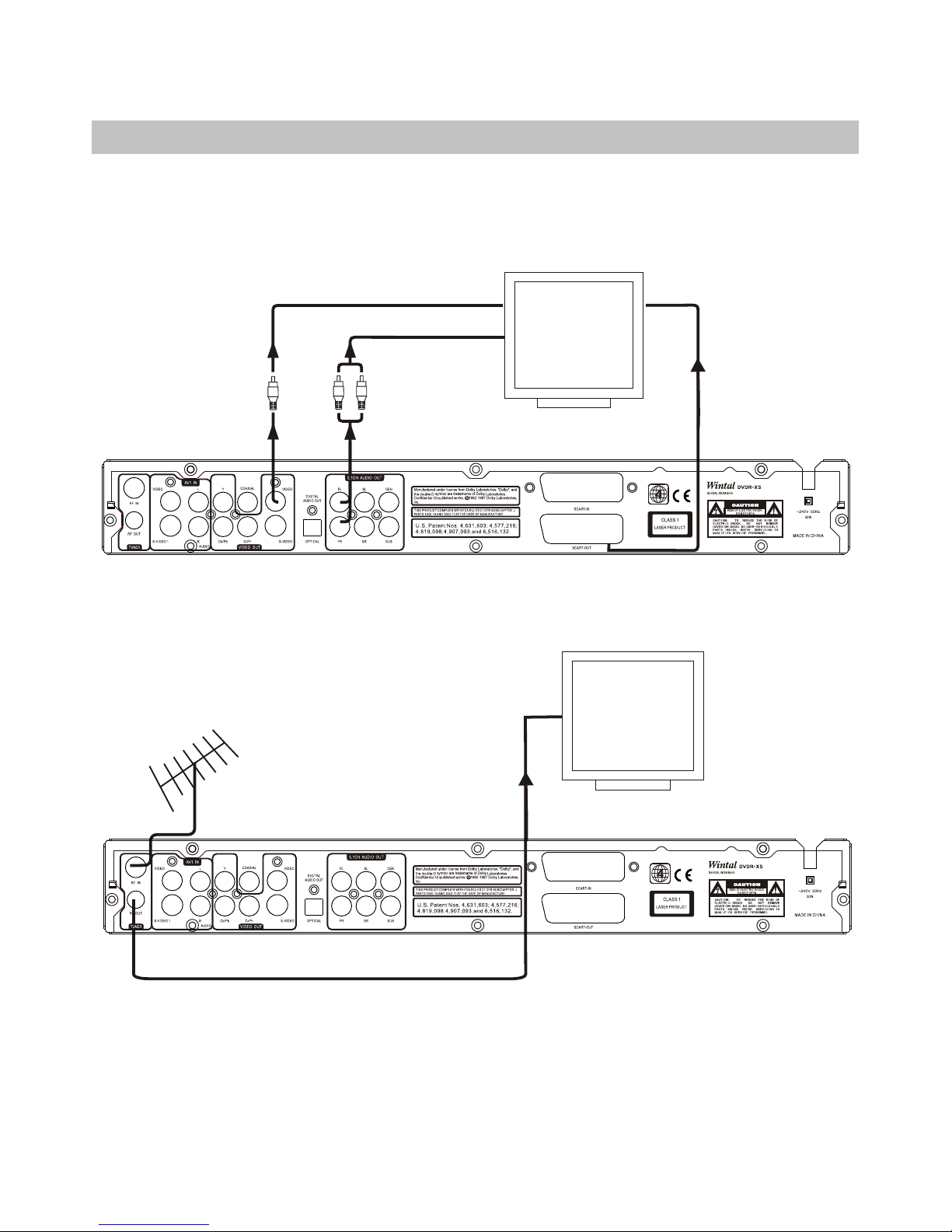
Connecting the Video output to your TV . . . . . . . . . . . . . 16-17
Aud io ou tpu t con nec tio ns . . . . . . . . . . . . . . . . . . 18
Ant enn a & TV co nne cti ons . . . . . . . . . . . . . . . . . . . . . . 1 8
Connecting Audio/Video recording
sou rce s to th e A/V In put s . . . . . . . . . . . . . . . . . . . . . 19
AV Inputs (VIDEO IN2, S-VIDEOIN2). . .. . . . . . . . .. . .. . 19
DVD RECORDER OPERATION
Pow eri ng on t he un it . . . . . . . . . . . . . . . . . . . . . . 20
Ini tia l Set up Pr oce dur e . . . . . . . . . . . . . . . . . . . . . . . . . . . . . 20
Usi ng th e men us . . . . . . . . . . . . . . . . . . . . . . . . . 20
Ins ert ing a D isc . . . . . . . . . . . . . . . . . . . . . . . . . . . . . . . . . . . . . 21
Usi ng Di sc me nus . . . . . . . . . . . . . . . . . . . . . . . . . . . . . . . . . . . 21
Bas ic di sc pl ayb ack . . . . . . . . . . . . . . . . . . . . . . . . . . . . . . . . .. 22
Adv anc ed pl ayb ack . . . . . . . . . . . . . . . . . . . 2 3
Slo w mot ion p lay bac k . . . . . . . . . . . . . . . . . . . 23
Rep eat ing a s egm ent y ou de fin e . . . . . . . . . . . . . . . . . . . 23
Mul ti- ang le fu nct ion . . . . . . . . . . . . . . . . . . . 2 4
Cha ngi ng th e aud io tr ack . . . . . . . . . . . . . . . . . . . 2 4
Sub tit les . . . . . . . . . . . . . . . . . . . . . . . . . . . 2 4
View ing J PG fi les . . . . . . . . . . . . . . . . . . . . . . . . 2 5
Pla yin g MP3 f ile s . . . . . . . . . . . . . . . . . . . . . . . . . . . . 25
RECORDING
Int rod uct ion t o rec ord ing . . . . . . . . . . . . . . . . . . . . . . . . 2 6
Set tin g rec ord ing o pti ons . . . . . . . . . . . . . . . . . . . 2 7
Set tin g the a uto c hap ter o pti on . . . . . . . . . . . . . . . . . . 27
Che cki ng th e Time a nd Da te . . . . . . . . . . . . . . . . . . 27
The Ti tle s cre en . . . . . . . . . . . . . . . . . 28
Type s of Re cor din gs . . . . . . . . . . . . . . . . . . . . . . 28
Mak ing a L ive R eco rdi ng . . . . . . . . . . . . . . . . . . 28
Recording 29
Tim er Re cor din g . . . . . . . . . . . . . . . . . . . . . . . . . 29- 30
SYSTEM SETUP
Gen era l . . . . . . . . . . . . . . . . . . . . . . . . . . ..3 1
Pla yba ck . . . . . . . . . . . . . . . . . . .. 31
Rec ord . . . . . . . . . . . . . . . . . . . . . . . . . 3 2
Lan gua ge . . . . . . . . . . . . . . . . . . . . . . . . . . .3 3
Cha nne l sca n . . . . . . . . . . . . . . . . . . . . . . . . .34
Clo ck . . . . . . . . . . . . . . . . . . . . . . . . .. 35
MODE SELECT . . . . . . . . . . . . . . . . . . . . . . . . 36- 37
DISPLAY . . . . . . . . . . . . . . . . . . . . . . . . ..3 7-3 8
Edi t a tit le of D VD+ RW . . . . . . . . . . . . . . . . . . . . . . . . 39
Cha pte r edi t . . . . . . . . . . . . . . . . . . . . . . . . 39
Edi t a dis c of on t he DV D+RW . . . . . . . . . . . . . . . . . . . . . . . 4 0
TROUBLE SHOOTING
Pla yba ck . . . . . . . . . . . . . . . . . . . . . . . . . . . . . . . . 41
Recording . . . . . . . . . . . . . . . . . . . . . . . . . . . . . . . 41
SPECIFICATION . . . . . . . . . . . . . . . . . . . . . . . 42
ATTACHMENT. . . . . . . . . . . . . . . . . . . . . . . . . . . . . . 43

9
DVD+R/RW Recorder and Progressive Scan Player
JPG
PROGRESSIVE
SCAN
Your DVDR-X5 is a progressive scan DVD Recorder. The recording provides you the ability to create your own
DVD discs from your home movies, favorite TV programs and more. Because of the outstanding compatibility
of DVD+R/RW discs, the discs you create will be suitable for playback in most DVD Recorders. You can record
from the unit's built-in TV Tuner oran external video source like a video camera. And when you're ready to
watch your recordings or commercial DVDs, you can enjoy them in the highest quality with the unit's
Progressive Scan Video Out and Digital Audio Out.
DVD+R/RW Recorder
l Record from your TV, camcorder,VCR, CD's, DVD's
lLive, Timer and Scheduled Recording Functions
lMultiple Recording Modes,HQ, SP, EP, SLP
lUp to 6 Hours Recording on one DVD+R/RW Disc
lOn-Screen Disc Title Navigator gives you quick,
easy access to your Recordings
lBuilt-In TVTuner, Front and RearA/V Inputs
lEditing features with Add/Del, Hide Chapters
lYour recordings are playable on most DVD
Recorders
Progressive Scan DVD+R/RW
lProgressive Scan Video with 3:2 pull down
Playback DVD+R, DVD+RW, DVD- R, DVD-RW,
DVD, CD-R, CD-RW,SVCD, Mp3, JPEG,HDCD
Kodak Picture CD.
lComponent Video, S-Video and CompositeVideo
Outputs
l96 kHz /24 bit D/Aconverter
lStereo Audio out, Opticaland Coaxial digitaloutputs.
lAdvanced playback functions:Slow playback, repeat
playback, parental control,MP3 player,JPG player,
screen saver,Zoom In/Out, trackselection, on-screen
display and more.
INTRODUCTION

10
INTRODUCTION
Optical disc compatibility
This unit iscompatible with awide range ofavailable
optical discs for recording and playback.
Discs suitable for Recording and Playback
Youmust use DVD+Ror DVD+RWdiscs to recordon this
unit.
DVD+R: These discs canonly be writtento once. Existing
recordings can behidden but notdeleted. So, anydisc space
already used bya recording cannotbe regained. DVD+R
discs are requiredto be "Finalized"before they willbe
compatible with standardDVD Recorders. Oncea disc is
finalized, no furtherrecordings can bemade.
DVD+RW:DVD+RW discs can bewritten to anderased
multiple times. Existingrecordings can bedeleted and disc
space regained. These discs do not require a finalization
procedure. As soon asa recording ismade, the discwill be
compatible with standardDVD Recorders.
Discs suitable for Playback Only
Units sold in Oceania are coded for Region 4, and are
compatible with discsmarked accordingly.
44
DVD-R/RW:These discs canbe played back when
recorded in standardDVD Video format.
TM TM
TM TM
CD-AUDIO: An on-screen navigatoris provided to
select and playtracks when usingCD-Audio discs.
CD-R/RW:This unit features an on-screen navigator for
easy access toplayable files storedon CD-R/RW discs,
such as JPGimages and MP3music.
Caring for Optical Discs
1. Hold a disc by the rim or with an index finger in the
central hole. Nevertouch the signalsurface.
2. Finger printsor stains onthe surface ofthe disc may
cause signal loss.
3. Use asoft cloth and wipe in a radiating manner from
the center of the disc to the outer rims when cleaning
the disc surface.
4. Never add labels or adhesive tapes on the discs be
careful not toscratch or damagethe disc surface.
5. To prevent discs from becoming bent or deformed,
they should bevertically kept inthe disc storagecase.
to prevent damage,avoid leaving discsin your car,
where they may be subject to direct sunlight and high
temperature.
6. Do notuse any discaccessory to improvethe audio
quality, disc protective solutionsor lens cleaner.
these products maydamage the discsurface.
Labels
Tapes
Labeling Side
Surface

11
INTRODUCTION
Make sure the package contents are complete
In addition tothe DVD recorder, your package contains the following accessories.
Remote control Batteries (7) AAA
A/V cable (Composite
Manual
Installing batteries in the remote control
This unit comescomplete with batteriesfor the remote
control. When installing batteries, be sure to take note of
the polarity markings on the inside of the battery
compartment and match them up with those on the
batteries.
1
2
Slide off the back cover
Install the batteriesin
the compartment.
Notes on batteries
1. If theremote control functionsbetter when it is closer to the unit,
the batteries maybe running low.
2. In caseof any leakageof batteries, disposethe batteries
right away andavoid touching thechemical discharge.
Make sure to clean the remote control's battery
compartment before installingnew batteries.
3. Do notmix batteries ofdifferent types, or use oldbatteries.
Operating the remote control
When using theremote control, besure to staywithin a
30degree angle of the sensor (More than 3 meter )on the
receiver. Keep in mind that any obstructions between
the remote controland the receiverwill effect
performance.
Video, StereoAudio)
30 30

FUNCTIONAL OVERVIEW
Remote Control
1
2
3
22
23
8
9
25
28
29
27
30
31
9
13
10
12 32
39
34
35
14
18
26
13
16
24
30
11
1. OPEN / CLOSE - Open and
close the disctray.
2. ZOOM -Press to magnify the
screen with DVDand JPG discs
3. A-B REPEAT - Sets the
beginning and endpoints of a
section to repeat.
4. REPEAT - Selects a repeat
option Chapter,Title orDisc.
5. SLOW -Slow motion playback
mode in ,1/2,1/4or 1/8 speed.
Press PLAY toresume normal
playback.
6. REC MODE - Selects the
recording quality mode- HQ, SP,
EP,SLP.
7. REC - Press to begina live
recording.
8. SETUP - Accesses the on-screen
setup Menu forsettings
adjustment. Use directionkeys
(UP/DOWN/RIGHT/LEFT)- To
highlight the itemyou desired.
9.UP/DOWN/RIGHT/LEFT-To
choose the itemyou desired.
10. STEP- Step to stepto playback
discs.
11. F.REV/F.FWD- Scan in fast
reverse or forwardon DVD and
other discs.
12. PAUSE - During playback of
a disc, chapteror track. Press
PAUSEto pause.
13/14. (CH+/-)/ -In TV tuner mode,
use to selecta channel.
15. AUDIO - Selects an audiotrack
on DVD discs and other discs.
16.MODE SELECT- PLAY,
EDIT RECORD, DISCMENU,
SETUP MENU,TIMER.
17. PAL/NTSC -Select the video
system for PAL, NTSC or multi
system.
18. DISPLAY - Brings up the on-
screen display showing
information for theplayback
session.
19. TIMER - Accesses the timer
menu for scheduledrecording
Setup.
20. EDIT -Accesses the editmenu
for DVD+R/RWediting options.
numeric values whilesetting
options.
21. STANDBY -Turns theunit on
and sends theunit to Standby
mode.
22. NUMBER KEYS- Use to enter
numbers.
23. GOTO - To Select your desired
time, chapter ofthe disc toplay.
24. ADD/CLEAR - When entering
input, use todelete characters.
25. SOURCE - Selects the input
video source forrecording. Choices
include built-in TVTuner and AV
Inputs,. SCART IN(if support),S-
VIDEO INPUTS DVIN.
26. DVD/TV -Switches between
Live Recording modeand DVD
Recorder mode.
27. MENU - Accesses Menu DVD
Discs.
28. SELECT - Selects options in
menus. Plays adisc, chapter or
track with somediscs. For other
discs, press PLAY.
29. RETURN -Resume playback for
DVD discs andother discs.
30. NEXT/PREVIOUS - Advanced to
the next trackor plays previous
track on DVDand other disc.
31. PLAY- Playback or Pause the
disc.
32. STOP -Press once tostop
playback and holdthe last position
in memory. Playback canbe
resumed where itwas left off by
pressing PLAY. Press twiceto
clear the lastplayback position.
33/34. VOL(+/-) -Use to select
volume +, -.
35. TITLE -Accesses the title screen
on DVD+R/RWdiscs, displaying a
graphical representation ofthe
recordings and providingeasy
navigation.
36. ANGLE - Selects between
multiple angles withDVD Discs
that support thisfeature.
37. SUBTITLE -Selects available
subtitles on DVDdiscs.
38. PSCAN -Select the videoout
format for progressivescan mode or
Interlace TV.
39. MUTE -Temporarily cancels
audio playback.
40. DISC OPER - Play\Recording
Disc\over write Disc\Lock Disc.
12
4
5
7
6
31
33
15
36
17
37 38
20 39
19
40
21

13
FUNCTIONAL OVERVIEW
Front Panel
9. REC MODE - Selects the recording quality mode
HQ, SP, EP, SLP.
10. SOURCE - Selects Input Sources when the
Recorder is inLive Record mode- TVTuner, VIDEO
IN 1 / 2, S-VIDEO IN 1 / 2, DV, SCART (if support).
And switch DVDRecorder mode tolive recorder
mode.
11.DV IN (1394FIRE WARE)-The i-link(1394 fire
ware)DV input Jack connect theDV or Digtial
camcorder for recording.To select this input,use the
SOURCE button and choose DV IN.
12.S-VIDEO INPUT - S-VIDEO input for recording.
Toselect this input, use the SOURCE button and
choose FRONT S-VIDEO.
13.STEREO AUDIO INPUTS - Use with S-VIDEO
IN or VIDEO IN forrecording.
14.VIDEO INPUT - Composite Video input for
recording. To select this input, use the SOURCE
button and choose FRONT CVBS.
12345678910
11 12 13 13 14
1. STANDBY - Turns the unit on and sends the
unit to standbymode. In standbymode, the unitwill
use a minute amount of power to enable power-on by
the remote control.
2. DISC TRAY- Loads DVD+R/RW,DVD, CD,
SVCD, MP3, JPGand other opticaldiscs.
3. VFD DISPLAY- The front Display shows
information about the unit's operation, such as current
chapter and elapsedtime during playbackand disc tray
status.
4. REMOTE RECEIVERS
5. OPEN/CLOSE - Press to open or close the
disc tray.
7. STOP - Press once to stop playback of a disc and
save the location of the stop point. The disc can be
played back fromthe stop pointby pressing PLAY. To
erase the stop point and reset the play location to the
beginning of thedisc, press STOP asecond time.
8. RECORD - Begins a Live Recording.
6. PLAY/PAUSE - Begins playback ofa disc,
chapter or track.Press again duringplayback to pause,
and again to resume playback.

14
FUNCTIONAL OVERVIEW
Front VFD Display
1. FUNCTION INDICATORS
Indicate the statusof advanced discplayback
Functions:
REPEAT Repeat chapter functionis active.
REPEATALL Repeat Disc function is active.
REPEATA-B Repeat A-B function is active.
A-B Repeat A-B Function is active.
REC Recording indicator.
ANGLE Multi-Angle Mode isactive.
PROGRAM Tracks are being played in PROGRAM
order.
RANDOM Tracks are being played in RANDOM order.
PBC PBC (Playback Control) Function is enabled.
These indicators show the playback status of a
DVD, CD orother optical disc-Currently Playing,
Paused.
2. TV TYPE INDICATORS
These indicators showthe TV TYPE-PAL:P, NTSC:N
3. PROCESSOR INDICATORS
These indicators display the status of the surround
sound processors andtype of soundtrack currently
active. CHANNELthe TV channel indicates
DOLBY the Dolby Digitalprocessor is active.
L/R The L/R option is active.
4. AM O R PM INDICATORS
These indicators showthe current timeis ante
5.DISC TYPE INDICATORS
Displays the typeof optical discinserted - DVD,
SVCD,CDDA (Music CD), or MP3.
6.TITLE /CHAPTER/TRACK INDICATOR
Displays the number of the current Title, Chapter or
Track on DVD, Music CDs and other discs.
7.MULTI-FUNCTION DISPLAY
When playing a DVD or other optical disc, displays
the elapsed time of the playback session or track.
Also displays disc tray status, system messages and
more. When the unit is in Standby Mode, displays the
system clock.
8.WEEK DAYS
Displays the current week days.

15
FUNCTIONAL OVERVIEW
Back Panel
1. RF IN / O UT - For Antenna or Cable TV
connection. Pass through connection to TV does not
transfer the outputsignal from theDVD Recorder.
*Some units do not have a Pass through connector. In
this case, use a splitter (See page 18).
2. VIDEO1 INPUT - Composite Video input for
recording. To select this input, use the SOURCE
button and choose Rear CVBS.
3. S-VIDEO1 INPUT - S-VIDEO input for recording.
Toselect this input, use the SOURCE button and
choose Rear S-VIDEO.
4. STEREO AUDIO INPUTS - Use with S-VIDEO1 IN
or VIDEO1 IN for recording.
5. COMPONENT/PROGRESSIVE SCAN VIDEO
OUTPUT - Use this output with TVs supporting
component Video or Progressive Scan input for best
video quality. Select this output in the DVD Recorder's
SETUP MENU.
6. COAXIAL DIGITAL AUDIO OUTPUT - Use a
special coaxial digital audio connector to send the
RAWcode or LPCMdigital signal todevices
supporting digital decoding.
7. COMPOSITE VIDEO OUTPUT - Standard Video
Output supported by most TVs.
8. S-VIDEO OUTPUT - Connect to TVs with S-
VIDEO in for better picture quality than standard
composite video.
9. OPTICAL DIGITAL AUDIO OUTPUT - Use to
connect to a receiver or other device with 5.1
channel decoders. This output isthe coded digital
signal.
10. 5.1CH AUDIO OUTPUT - Connect to TVs or
other Audio equipment supporting 5.1CH audio in.
11.SCART INPUT-Scart Composite Video or RGB
video input for recording. Toselect this input, use
the SOURCE button and Choose SCART IN.
12.SCART OUTPUT-use this outputwith TVs
Supporting RGB Video or Composite Video. RGB
Video is best quality. Select this output in the DVD
Recorders SETUP MENU.
1
12
3
4567
8912
10 11

16
CONNECTIONS
Connecting the video output to your TV
In order to use the DVD Recorder, you'llneed to make a video connection to your TV. The capabilities of your TVand
the cables youhave on handwill determine theconnections you canuse. There are 4 possibleconnection types:
- Composite Video - The most widely used connection. This unit includes an A/V cable for Composite Video.
- S-Video - A higher quality connectionthat requires aspecial S-Video cable andan S-Video capable TV.
- Component Video - The highest quality video connection. Supported on high-end TVs and requires a special
cable.
- SCART-Itcontains two qualityvideo(Composite and RGB).It requires a specialcable.
Composite Video (Typical connection)
This unit ships with a composite video (A/V) cable for connection to TVs with a standard video input as shown below.
This is themost widely usedtype of connection.On most TVs, this connectoris colored yellow, and is normally
accompanied by stereoaudio inputs, coloredred and whitefor stereo channelsright and leftrespectively.
12
3
First, use the supplied A/V cable to connect to the
composite video input on your TV. This is normally a
yellow-colored connector that matches the Video output
on the back of this unit. If you wish to hear sound
through the TV, connect the red and white stereo audio
connections as well.
Turn on the TV and DVD Recorder and select the DVD
Playback mode with the remote control.
On your TV , select the video input. This is normally done
by selecting video 1or video Input with the remote
control. On some TV s, this is done by selecting a
particular channel.
Composite Video
Input Jack
Composite Video /
Stereo Audio Cable
V
TV with
Composite
Video Input
(Typical
Connection)
VIDEO INPUT
R
STEREO AUDIO IN
L
TV with
SCART
input
,

1 2
3
17
CONNECTIONS
S-Videoor componentvideo output
This isa higherquality connectionthan standardcomposite video,and requiresa specialS-Videocable notincluded.
The S-Video connector isdistinguishable by its4 pins, asshown below. If yourTV hasan S-Video input, it's
recommended that youuse this typeof connection forbetter picture quality.
Turn on the unit and select the DVD mode.
Component Video
The highest qualityvideo connection, componentvideo requires separatecables for theY, Pb/Cb, Pr/Cr signals. To
use theprogressive scanoption onthis unit,you'll needto usethe componentvideo output.Using thecomponent
video outputrequires thesesteps:
1
2
First, use thesupplied A/Vcable to connectto the
component video inputon yourTV.Select this input.
Changing theTV OUTMODE to theprogressive scan by
press the PSCANand SELECTkey.Select the correct
video input onyour TV.
Component Video
Input Jacks
Y
Pb/Cb Pr/Cr
Component
Video Cable
Resetting thevideo output
If you inadvertentlyswitch the OUTPUTFORMATsetting to
PROGRESSIVE while usinga standard TVnot capable of
PSCAN, you willlose video. Ifthis happens, resetthe
recorder to itsdefault video settingsby pressing PSCAN
and SELECT onthe remote.
YPb Pr S
LR
S-Video
Input Jack S-Video Cable
TV with
Component
Video Input /
Progressive Scan
cap ability.
VIDEO
INPUT
TV with
S-Video Input
VIDEO
INPUT
First, a specialS-Video cable.Connecting the S-
Video outputfrom the unitto the correspondinginput
on yourTV.
On yourTV,select the s-videoinput. Thisis
noumally done byselecting Ycb/cror Ypb/pr or
S-VIDEO With theremote control. Onsome TV S
this is doneby selecting aparticular channe.

18
CONNECTIONS
Audio OutputConnections
Antenna &TV Connections
This unit isavailable with andwithout anantenna passthrough connection. For units withanAntenna input
connector and withpass through connector, as shownbelow to theleft , useantenna or cableTV connectionto
connect RF inputand RF outconnect aTV.
This unit featuresa variety ofaudio line outputsfor connection toa receiver orother audio equipment.
- Use the includedA/Vcable to connectthe stereo audiooutputs for connectionto aTV orstereo receiver.
- Optical andCoaxial digitalaudio outputssend anencoded digitalbitstream, suitablefor receiverswith Dolby
decoding capability. Theseoutputs requirespecial cablesnot included.
Receiver with Digital
Audio Input
COAXIAL DIGITAL AUDIO IN
OPTICAL DIGITAL AUDIO IN
R
STEREOAUDIO IN
TV or receiver
with stereo
audio in
L
TV with
coaxial
antenna or
cable TV
connection
ANTENNA OR CABLE TV CONNECTION ANTENNA OR CABLE TV CONNECTION
TV with
coaxial
antenna or
cable TV
connection
IN
OUT OUT
Splitter
OR
With Passthrough Connector Without Passthrough Connector

19
CONNECTIONS
ConnectingAudio/Videorecording sourcesto theA/VInputs
Audio/Videoinputs are providedon the frontside and backof the unitfor connection ofoutside audio/video sources
such asVCRs, camcorders, DVDRecorders, etc. ExternalVideoSources must supportS-Video,Composite Video
and/or StereoAudioto besuitable forrecording.
AV Inputs(VIDEO IN2, S-VIDEOIN 2)
Audio/Video source such as
DVD player or VCR with
Composite Video Out
Audio/Video source such as
camcorder supporting
S-VIDEO Out
LR
V
VIDEO IN 2 S
LR
S-VIDEO IN 2
COMPOSITE VIDEO /
STEREOAUDIOOUTPUT
S-VIDEO / STEREO
AUDIO OUTPUT
DIGITALVIDEO OUTPUT
LRV
COMPOSITE VIDEO /
STEREOAUDIOOUTPUT
VIDEO IN 1
S
L R
S-VIDEO / STEREO
AUDIO OUTPUT
S-VIDEO IN 1
SCART INPUT
Audio/Video sourcessuch as
DVD playeror VCRwith
Composite VideoOut
Audio/Video sourcesuch as
camcorder supporting
S-VIDEO Out

Notes on Power states
¡°¡±
20
DVD RECORDEROPERATION
Powering onthe unit Initial SetupProcedure
Only afterall connectionsare complete,connect the
power cord andpower on theunit.
1
2
Plug the standardjack end intoa wall socketor
power strip.
Press STANDBY onthe remote controlor front panel
to bring thesystem out ofstandby mode.The system
is now readyto use.
There are 3power states forthis unit:
1. OFF- notconnect thepower cord.The unitdraws no
power and cannotbe turned onby the remotecontrol.
2. STANDBY - theunit hasnot beentaken outof standby
by pressingeither theSTANDBYkey on theremote
control orthe STANDBYbutton on thefront panel.
The unitdraws aslight amountof powerto enablethe
remote control receivingcircuit.
3. ON - the standbybutton onthe remotecontrol orthe
standby buttonon thefront panelhas beenpressed.
The unit isready to use.
Using theMenus
When the unitis first poweredon, you'll beprompted to
set thetime anddate aswell asTVTuner options.You
can alwayschange anyof thesettings youchoose
during theInitial Setuplater inthe DVD Recorder's
SETUP MENU.
2
Use the UP/DOWNkeys to increaseor decrease the
value of aselected field ormove to afield above or
below. Usethe LEFT/RIGHTkeys to moveto the
previous or nextfields.
Press SELECTto select anoption and/or continue.
Time andDate
Setting theTime andDate correctly isimportant, as theTimer
recordings depend onan accurate setting.The Time format
used is 24HR. Use theUP/DOWN keys to increaseor
decrease theTime orDate and theLEFT/RIGHT keys to
move to adifferent field.When you'redone, move toDONE
and pressENTER.
The Initial Setupis now complete.Remember, anysettings
chosen during theInitial Setup canbe changed atany time in
the DVD Recorder's SETUP MENU. PressSETUPto exit the
Initial Setup andbegin using yourDVD Recorder.
Date(mm/dd/yy)
Time(hh:mm:ss)
01/01/ 01
21:45: 23
Date(mm/dd/yy)
Time(hh:mm:ss)
01/01/ 01
21:45: 23
Press RETURN/EDIT to exit edit mode,
Press UP/DOWN or 0-9 to edit.
SYSTEM SETUP CLOCK SYSTEM SETUP CLOCK
1
Table of contents
Other Wintal DVD Recorder manuals