Winterhalter PT ClimatePlus Series User manual

Winterhalter PT ClimatePlus
PT Series
Manual
ClimatePlus heat pump


1
Table of contents
1About this manual -------------------------------------------------------------------1
2Safety notes----------------------------------------------------------------------------2
3Conditions for switching on------------------------------------------------------2
4Flow schema---------------------------------------------------------------------------3
5Important components and spare parts--------------------------------------4
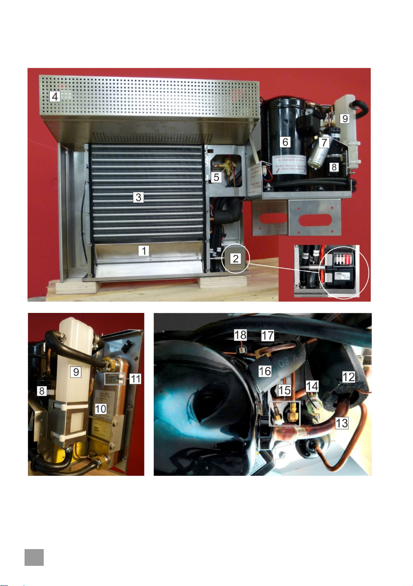
5.1On the heat pump ---------------------------------------------------------------------4
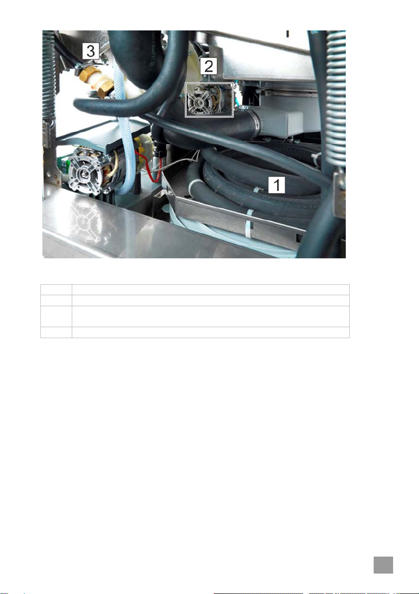
5.2On the machine ------------------------------------------------------------------------6
6Troubleshooting and remedy ----------------------------------------------------8
6.1Water-related safety ------------------------------------------------------------------8
6.2Overview of the troubleshooting diagram----------------------------------------8
7Service--------------------------------------------------------------------------------- 19
7.1Clean lamella heat exchanger---------------------------------------------------- 19
7.2Descale plate heat exchanger---------------------------------------------------- 20
8Instalment and replacement of the heat pump--------------------------- 21
9Technical data----------------------------------------------------------------------- 21
1 About this manual
The following symbols are used in these instructions:
Symbol Meaning
Danger
Warning against potential serious or fatal injuries to persons if
the described precautionary measures are not taken.
Warning
Warning against potential minor injuries to persons or potential
material damage if the described precautionary measures are
not taken.
Caution
Warning against defects in or destruction of the product if the
described precautionary measures are not taken.
IMPORTANT Important information is given here.
INFO Useful information is given here.
This symbol indicates instructions.
This symbol indicates results of your actions.
This symbol indicates itemisations.
This symbol refers to a chapter with more detailed information.

2
2 Safety notes
Danger
Danger of death: live components!
Isolate the machine from the mains electrical supply. Check that
there is no voltage.
Warning
Wear protective clothing, protective gloves and protective goggles
when handling chemicals.
Ensure while replacing or changing the wiring that the connections given in
the circuit diagram are adhered to.
Smoking and open flames are prohibited.
When working on the heat exchanger, make absolutely sure not to bend or
damage the lamellae. Otherwise the functioning of the heat exchanger is no
longer guaranteed.
Working on the refrigeration cycle
Danger
Risk of suffocation due to oxygen deficiency
Leaking refrigerant can result in accumulation at ground level.
Warning
Repairs to the refrigeration cycle may only be carried out by expe-
rienced refrigeration technicians. Improper repairs may cause sig-
nificant danger for the user, for which Winterhalter is not liable.
3 Conditions for switching on
The heat pump heats the tank water by means of an intermediate circuit. As
soon as the minimum tank level (dry running protection) has been reached, the
heat pump switches on and extracts energy from the ambient air. During rins-
ing or in stand-by mode, the heat pump always switches on as soon as the
tank temperature has fallen below the rated temperature and remains active
until the tank temperature has exceeded the rated temperature by 3 °C.
INFO In the self-cleaning programme the heat pump does not switch on.

3
4 Flow schema
Item Description
1 Compressor
2 Plate heat exchanger
3 Thermal expansion valve
4 Lamella heat exchanger (evaporator) with ventilator
5 Boiler
6 Tank
7 Rinse pump
8 Inlet solenoid valve
9 Circulating pump for tank heating
10 Circulating pump for intermediate circuit
11 Water safety device (air gap / BPD)
12 Compensator reservoir
13 Non-return valve
14 Subcooler or superheater
15 Air vent
16 Coaxial heat exchanger
17 Waste water heat exchanger
18 Drain pump
Fresh water
Refrigerant circuit
Tank water
Waste water Fresh water Exhaust air
Waste
wate
r
Rinse
A
mbient ai
r
Machine air

4
5 Important components and spare parts
5.1 On the heat pump

5
Item Description Note Material No.
(Spare part)
1 Air vent
(vapour extraction from the
interior of the machine or am-
bient air)
2 Air vent motor 230V/50 Hz 30002159
3* Lamella heat exchanger Copper 30008157
4 Ventilation grill
5* Thermal expansion valve
Jet 30008160
30008161
6* Compressor 30008155
7 Condenser 40 µF/450 V 30002781
8 Filter dryer 30008158
9 Compensator reservoir
10* Plate heat exchanger 30008156
11 Thermal sensor kit 30002179
12 Hot gas thermostat
Switch-off temperature:
130 °C
Switch-on temperature:
97 °C
30008164
13 Hot gas line
14* High-pressure switch Switch-off pressure: 27 bar
Switch-on pressure: 20 bar 30008163
15 Service access valves
16 Low pressure line (suction line)
17* Inspection glass with colour
indicator wet refrigerant: yellow
dry refrigerant: green 30008159
18* Low pressure switch Switch-off pressure: 0.2 bar
Switch-on pressure: 1.0 bar 30008162
Lamellae comb without depiction 3106221
IMPORTANT The filter dryer must always be replaced along with parts of
the refrigeration cycle which are marked with “*“.

6
5.2 On the machine
Front view
Item Description
1 Boiler
2 Circulating pump for intermediate circuit (Material No. 61008622)
200-240V/1/50-60Hz
3 Advanced PCB (Material No. 30002168)
4 Universal power unit (Material No. 30002171)
+ 2-part bridge comb (Material No. 30001592)
(1x at 400V/415V,3N~ and 2x at 230V 3~)
5 AF16:3S:1Ö contactor (Material No. 30000861)
100-250V/50-60Hz
6 Circuit breaker (Material No. 30002641)
S201-K161
2-POLE; 16A-K (1P+NA)
1 Only a circuit breaker in coupled 2-pole configuration (with simultaneously switching neutral conductor) may be used
as a spare part.

7
Rear view
Item Description
1 Coaxial heat exchanger
2 Circulating pump for tank heating 0.2 kW, 200-240V/1/50-60Hz
(Material No. 3102561)
3 Non-return valve

8
6 Troubleshooting and remedy
Warning
Repairs to the refrigeration cycle may only be carried out by expe-
rienced refrigeration technicians. Improper repairs may cause sig-
nificant danger for the user, for which Winterhalter is not liable.
IMPORTANT You may only test the heat pump if the minimum tank level
(dry running protection) is adhered to and the cover is mount-
ed on the lamella heat exchanger. This is the only way to en-
sure air flow.
6.1 Water-related safety
To ensure fault-free operation, it is important that parameter P630 is set in
accordance with the installed water safety device.
Access the Service Menu and check whether the parameter is set correctly
(for details see PT Series service instructions):
‒For machines with backflow restrictor type “air gap” (30000127): 50 °C
‒For machines with backflow restrictor type “BPD” (30000128): 70 °C
6.2 Overview of the troubleshooting diagram
Error Description Page
1 Heat pump will not start up although tank temperature is
below rated temperature 9
2 Heat pump is working, but generating loud noises 10+11
3 Heat pump is working, but tank temperature cannot reach
the rated temperature 12
4 Error 56 – Heat pump safety circuit 13-15
5 Error 57 – No increase in temperature in the intermediate
circuit (I22) while compressor is active 16
6 Error 58 – Temperature sensor on plate heat exchanger
(I22) defective 17
7 Error 70 – More than ten heat pump cycles of operation
per hour 18
1A, 1B, 1C, … = error code; enter in error log

9
1A
Compressor thermal protector tripped
INFO Thermal protector resets automatically after cool-
ing down (at least 30 minutes).
Then start the heat pump.
Measure the operating currents: Set value: 4.8 – 8.2 A in
L3 phase if Q1 contactor is engaged.
1B
Fault in the circuit
Remedy: Find and eliminate the fault using the circuit
diagram
1C
Compressor defective
Test:
Rated current 4.8 – 8.2 A in L3 phase if Q1 contactor is
engaged.
Remedy: Have repair carried out by experienced refrig-
eration technician.
1
Heat pump will not start up although tank temperature is
below rated temperature and dry running protection level
is adhered to (3)

10
2A
Defective electrical wiring
Remedy: Rectify electrical connections.
2B
Bearing damage in the ventilator
Remedy: Replace ventilator.
2C
Bearing damage in the compressor
Remedy: Have repair carried out by experienced refrigeration technician.
2D
Knocking sound in the compressor
Remedy: Have repair carried out by experienced refrigeration technician.
2E
Defective thermal expansion valve
Indications: frozen thermal expansion valve
Remedy: Have repair carried out by experienced refrigeration technician.
2
Loud noises immediately after starting the heat pump
2
Heat pump is working, but generating loud noises

11
2F
Knocking sound in the compressor (liquid slugging)
Remedy: Have repair carried out by experienced refrigeration technician.
2
Loud noises after a certain period of operation

12
3A
Solenoid valve (O7) is “sticking” (is constantly open)
Fresh water constantly flowing through the intermediate circuit into the
boiler
Remedy: Replace solenoid valve.
3B
Inner tube of the coaxial heat exchanger dirty
Remedy: Clean / replace
3C
I22 temperature sensor defective
Remedy: Replace temperature sensor kit.
3D
Calcified plate heat exchanger
Remedy: Descale plate heat exchanger (7.2).
3E
Lack of refrigerant
Indication: constant bubbling in the inspection glass
Remedy: Have repair carried out by experienced refrigeration technician.
3F
Defective thermal expansion valve
Remedy: Have repair carried out by experienced refrigeration technician.
3
Heat pump is working, but tank temperature cannot reach the rated
temperature

13
4E
Is the lamella heat exchanger dirty or are
the lamellae deformed?
4D
Is the air flow through the lamella heat
exchanger obstructed?
4C
Water supply < 4 l/min?
4B
Parameter 630 set correctly (6.1)?
4A
Water inlet temperature > 20 °C?
4
Error 56 – Heat pump safety circuit tripped
yes
no
Continue to page 14
Ensure cold water supply.
yes
no
Ensure sufficient water supply.
yes
no
Clear air flow.
Clean lamella heat exchanger
(7.1) and straighten bent lamellae
with the lamellae comb.
no
yes
no
yes
Rectify parameter setting.

14
4J
Is heat pump’s hydraulic connection
correct? Check using the flow schema.
4I
Water level in compensator reservoir not
visible?
Indicative of leak in the intermediate
circuit/ non-return valve defective
4H
Circulating pump for tank heating defec-
tive / incorrectly connected?
4G
Intermediate circuit pump defective /
incorrectly connected?
4F
Ventilator defective / incorrectly connect-
ed?
yes
Repair / replace.
Replace non-return valve.
Fix leak.
Rectify.
no
no
yes
yes
no
no
Repair / replace.
yes
no
Repair / replace.
yes
Continue to page 15

15
4O
Air in the refrigeration cycle?
4N
Defective thermal expansion valve?
4M
Hot gas temperature too high?
Indicative of lack of refrigerant
4L
Are bubbles forming in the inspection
glass for extended periods?
Indicative of lack of refrigerant
4K
Plate heat exchanger calcified? Water
throughflow severely restricted.
Have repair carried out by experi-
enced refrigeration technician.
yes
Descale plate heat exchanger
(7.2).
no
yes
Have repair carried out by experi-
enced refrigeration technician.
yes
no
Have repair carried out by experi-
enced refrigeration technician.
yes
no
no
Consult with Winterhalter technical cus-
tomer care
Have repair carried out by experi-
enced refrigeration technician.
yes
no

16
5C
Compressor defective?
5B
Electrical connection of compressor
wrong? (Very loud operating noise, hot
gas line not heating)
5A
I22 temperature sensor defective?
5
Error 57 – No increase in temperature in the intermediate circuit (I22)
while compressor is active
yes
no
Replace temperature sensor.
yes
Have repair carried out by experi-
enced refrigeration technician.
yes
no
Rectify compressor’s electrical con-
nection.
Consult with Winterhalter technical cus-
tomer care
no

17
6B
Cabling defective?
6A
I22 temperature sensor defective?
6
Error 58 – Temperature sensor on plate heat exchanger (I22) defective
no
Replace temperature sensor.
yes
yes Repair cabling.

18
INFO Errors which lead to Error 56 may result in Error 70 subsequently be-
ing triggered.
7B
Tank temperature sensor (I15) defec-
tive?
7A
Water inlet temperature > 20 °C?
7
Error 70 – More than ten heat pump cycles of operation per hour
yes
no
Replace sensor.
Consult with Winterhalter technical cus-
tomer care
no
Ensure cold water supply.
yes
Table of contents