Wire wizard Powerball Installation manual

HIGH PERFORMANCE MIG WELDING GUNS
OPERATION MANUAL
For 300 and 400 Amp Semi-automatic MIG Guns
ELCo Enterprises, Inc. • Jackson, Michigan USA • Service & Support: 517-782-8040
www.wire-wizard.com

2
MIG WELDING GUN OPERATION MANUAL
Published by:
ELCo Enterprises, Inc.
5750 Marathon Drive • Jackson, MI USA. 49201
Phone: (517) 782-8040 • Fax: (517) 782-8039
www.wire-wizard.com
Last Revision Date: 5/9/2018
1.0 INTRODUCTION...............................................................................................................................3
1.1 Warranty ............................................................................................................................................3
1.2 Product Registration..........................................................................................................................3
2.0 SAFETY PRECAUTIONS ............................................................................................................. 4-5
2.1 Welding and Safety Operating References .......................................................................................5
3.0 DUTY CYCLE SPECIFICATIONS.....................................................................................................6
5.0 OPERATION .....................................................................................................................................6
5.1 Trigger Pull Adjustment......................................................................................................................6
6.0 CONSUMABLES REPLACEMENT..................................................................................................7
6.1 Torch Liner Replacement...................................................................................................................7
6.2 Gooseneck Replacement Instructions...............................................................................................8
7.0 TROUBLESHOOTING......................................................................................................................8
8.0 REPLACEMENT PARTS LIST .........................................................................................................9
9.0 TORCH CONSUMABLES & ACCESSORIES................................................................................10
TABLE OF CONTENTS

3
MIG WELDING GUN OPERATION MANUAL
1.0 INTRODUCTION
1.1 WARRANTY
1.2 PRODUCT REGISTRATION
Congratulations on your purchase of the PowerBall® High Performance MIG Welding Gun! Each PowerBall® Welding
Gun is proudly manufactured and inspected at our facility in Jackson, Michigan. Please check box contents upon
receipt for any damage that may have occurred during transit and to ensure all torch components are accounted for.
This guide is designed to assist the user whose primary responsibility is to operate and maintain the PowerBall® MIG
welding gun. This manual provides specic information on installation, safety, basic operation, and maintenance.
Please read, understand and follow all safety precautions noted in this manual.
For customer service and support, contact ELCo Enterprises at 517-782-8040 or toll free 1-866-584-7281. A digital
version of this manual and additional product information is available on our website at www.wire-wizard.com
LIMITED ONE (1) YEAR WARRANTY
ELCo Enterprises, Inc. (hereinafter “ELCo”) shall warrant this product to be free of defects in material and/or
workmanship for a period of one (1) year from the date of shipment to the buyer. The warranty shall cover 100% of
all parts and labor with the exception of misuse, abuse, neglect and typical consumables as determined by ELCo.
Failure to follow proper installation and/or maintenance procedures specied in the operating instructions will void
this warranty. ELCo will at its option, repair, replace or issue a credit for the value of the defective product within the
warranty period.
Buyer accepts all responsibility for compliance with any/all Local, State and Federal Laws or Regulations including
Regulations of Foreign Governments.
No equipment shall be returned to ELCo without a Return Authorization Number. Upon evaluation and validation of
warranty, replacements or repairs will be sent to the Buyer. If a replacement is needed immediately, a purchase order
is required to cover the cost of the product until the warranty is determined.
ELCo’s warranty is limited to replacing any goods that are proved to be defective and ELCo in no event shall have
any liability for paying incidental or consequential damages including and without limitation, damages resulting in
personal or bodily injury or death, or damages to, or loss of use of any property. Notwithstanding any of these terms
and conditions, the warranties set forth shall apply in connection with any sales of goods, services or design by ELCo
and are in lieu of all other warranties, express or implied, including warranties of merchantability and tness for a
particular purpose.
Please register this product online or by phone within 14 days after purchase
Register this product online by going to www.wire-wizard.com/register or scanning the QR code on
the right, or you may call 517-782-8040 to register by phone. Registering this product will allow us
to provide expedited service should there be any problems potentially covered by this warranty in
the future.
Please record the following information for this product and retain for your records:
Model #:_________________________ Lot #:______________________ Shipment Date:____________________
Online Registration

4
MIG WELDING GUN OPERATION MANUAL
2.0 SAFETY PRECAUTIONS
WARNING
Improper installation, use or maintenance of welding equipment may cause serious injury or death.
All operators must read and understand all safety warnings and instructions before installing or using
this welding gun. All operators must be trained in proper welding safety and operation procedures
prior to operating this welding gun. Please keep these instructions for future reference.
WARNING: ELECTRIC SHOCK HAZARD
Operators should always wear dry welding gloves and protective clothing when welding. Do not
contact electrically live parts. Keep welding guns and other welding equipment away from moisture
and water. Ensure ground connections are secure and compatible with the required electric current.
When welding under wet conditions or where perspiration is a factor, the use of automatic controls
for reducing the no load voltage is recommended to reduce the risk of electric shock. Accidental
contact must be prevented with open circuit voltage exceeding 80 volts AC, or 100 volts DC by
using insulation or other means. When welding gun is not in use, turn off power supply to prevent
any accidental contact.
Welding equipment should be installed and maintained in accordance with National Electrical Code
(NFPA 70) and in compliance with local codes. Equipment should only be serviced by qualied or
trained personnel only. Do not disassemble torch or change welding consumables with the power
supply on. See welding safety and operating references in section 2.1 for safety guidelines and
additional information.
WARNING: ARC RAYS AND SPARKS CAN CAUSE EYE INJURY AND BURNS
Always wear a federally compliant welding helmet with the proper lens when welding, along with
protective welding gloves and protective clothing. Protective clothing should cover all exposed skin
to prevent burns and exposure to ultraviolet rays. An approved welding curtain or solid wall must
be used in areas where other personnel may be exposed to arc rays. Other personnel in the work
area exposed to arc rays and sparks must also wear a welding helmet and protective clothing to
prevent eye injury and burns. Ear plugs should be worn to protect ears from sparks. Avoid using
ammable hair preparations when welding. Never attempt to weld without a welding helmet,
protective gloves and clothing. See welding safety and operating references in section 2.1 for
safety guidelines and additional information.
WARNING: WELDING SPARKS CAN CAUSE FIRES AND EXPLOSIONS
All combustible materials should be removed from the work area (at least 35 ft / 10.7 m) to prevent
res and explosions. Do not wear clothing soaked with oils, gasoline or other ammable liquids
while welding. Always keep a re extinguisher near the work area and understand its operation.
Do not weld containers that have contained ammable materials or liquids. Use only inert gases or
inert gas mixes required for the welding process. Do not use oxygen with a welding torch. Arcing
against compressed gas cylinders may cause damage to the cylinder or explosion. See welding
safety and operating references in section 2.1 for safety guidelines and additional information.
WARNING: SMOKE AND FUMES CAN BE DANGEROUS TO YOUR HEALTH
Ensure there is adequate ventilation to remove smoke and fumes from the work area to protect
operators and other nearby personnel. Avoid using chlorinated solvents in the work area that can
form Phosgene when exposed to UV arc radiation. An air supplied respirator must be worn where
ventilation is not adequate to remove fumes and vapors. Do not use oxygen for ventilation in the
work area. See welding safety and operating references in section 2.1 for safety guidelines and
additional information.

5
MIG WELDING GUN OPERATION MANUAL
2.0 SAFETY PRECAUTIONS
2.1 WELDING SAFETY AND OPERATING REFERENCES
WARNING: NOISE FROM WELDING CAN DAMAGE HEARING
Improper installation, use or maintenance of welding equipment may cause serious injury or death.
All operators must read and understand all safety warnings and instructions before installing or using
this welding gun. All operators must be trained in proper welding safety and operation procedures
prior to operating this welding gun. Please keep these instructions for future reference.
WARNING: ELECTRIC AND MAGNETIC FIELDS
The welding process generates Electric and Magnetic Fields (EMF). EMF elds may interfere with
some pacemakers. Operators with a pacemaker should consult their physician prior to welding.
EMF elds may also damage some electronic devices, such as computers and mobile phones.
Keep sensitive electronic devices away from work area to prevent damage.
WARNING: WELDING WIRE CAN CAUSE INJURY
Keep hand and other body parts away from end of welding gun in case of accidental activation of
the trigger. Weld wire can puncture skin and cause injury. Never point the gun toward the body or
or others when feeding wire.
Refer to these safety standards and regulations for additional information on best practices for welding safety:
• ANSI Z49.1 “Safety in Welding and Cutting”.
• ANSI Z87.1 “Practice for Occupational and Educational Eye and Face Protection”.
• ANSI Z88.2. “Standard Practice for Respiratory Protection”. American National Standards Institute,
1430 Broadway, New York, NY 10018.
• Code of Federal Regulations (OSHA) Section 29, Part 1910.95, 132, 133, 134, 139, 251, 252, 253, 254 and
1000. U.S. Government Printing Ofce, Washington, DC 20402.
• AWS F4.1. “Recommended Safe Practices for Welding and Cutting Containers”.
• AWS C5.3. “Recommended Practices for Air Carbon-Arc Gouging and Cutting”. The American Welding
Society, 550 NW Lejeune Rd., P.O. Box 351040, Miami, FL 33135.
• NFPA 51B. “Fire Prevention in Cutting and Welding Processes”.
• NFPA-7. “National Electrical Code”. National Fire Protection Association, Battery Park, Quincy, MA 02269.
• CSA W117.2. “Safety in Welding, Cutting and Allied Processes”. Canadian Standards Association,
178 Rexdale Blvd., Rexdale, Ontario, Canada M9W 1R3.

6
MIG WELDING GUN OPERATION MANUAL
3.0 DUTY CYCLE SPECIFICATIONS
4.0 INSTALLATION
5.0 OPERATION
5.1 TRIGGER PULL ADJUSTMENT
Duty cycle is dened as the percentage of 10 minutes the torch can weld at a rated load without overheating. The
data below shows the duty cycle ratings for PowerBall® Air-Cooled MIG Guns with both pure CO2 and mixed gases.
PowerBall® 300 amp and 400 amp MIG Guns have been tested for reliable operation at 100% duty cycle for
both pure CO2 and mixed gases.
INSTALLATION TO WIRE FEEDER
1. Insert feeder adapter (or Euro-style adapter) and
control plug into wire feeder and secure tightly.
2. Attach power cable to power source and secure tightly.
3. Feed wire to the gun by hand and tighten feeder drive rolls.
GUN MODEL AND MAX WIRE SIZE DUTY CYCLE RATINGS
400 amp Air-Cooled MIG Gun
Maximum wire size: 5/64” (2.0mm)
100% @ 400 amps with pure CO2shielding gas
100% @ 400 amps with 90/10 mixed Ar/CO2shielding gas
100% @ 400 amps with 75/25 mixed Ar/CO2shielding gas
300 amp Air-Cooled MIG Gun
Maximum wire size: 5/64” (2.0mm)
100% @ 300 amps with pure CO2shielding gas
100% @ 300 amps with 90/10 mixed Ar/CO2shielding gas
100% @ 300 amps with 75/25 mixed Ar/CO2shielding gas
Spring
Set Screw
Light, Medium &
Heavy Trigger Springs
Feeder Adapter
(design will vary)
Control
Plug
Power
Cable
PowerBall® MIG Guns feature an adjustable trigger pull with three tension springs for a light,
medium or heavy trigger pull. All guns ship with the medium pull spring pre-installed. To change
the trigger pull spring, use a 3mm Allen wrench to remove the set screw holding the spring in
place. Replace with desired spring and secure back in place with the set screw.
TRIGGER OPERATION
Pulling the gun trigger feeds energized wire and starts the ow of shielding gas. The trigger should only be pulled
when ready to strike an arc, when initially feeding wire to the gun or when adjusting wire stick-out. Keep hands and
other body parts away from the end of the gun when pulling the trigger to avoid injury from the welding wire.

7
MIG WELDING GUN OPERATION MANUAL
Trim Length:
5/8” (15.8mm)
6.0 CONSUMABLES REPLACEMENT
6.1 TORCH LINER REPLACEMENT
REPLACING THE TORCH LINER
1. Turn off power supply and detach welding gun from feeder.
2. Loosen the liner collet at the back end of the gun.
3. Remove the nozzle, tip, diffuser and old torch liner.
4. Uncoil and insert the new liner up through the back of the gun.
If it gets caught, rotate while pushing inward.
5. Push the liner all the way through the gun and place the end into the liner connector. Tighten the liner
collet onto the feeder adapter to secure in place.
6. Trim the torch liner to a stick-out of approx. 5/8” (15.8mm). When properly trimmed, the liner should travel all
the way into the diffuser. Smooth and deburr the end of the liner so there are no sharp edges. This will
prevent wire hang-up and other feeding problems from occurring.
7. Replace and tighten the diffuser, contact tip and nozzle. Re-attach the gun to the wire feeder and feed wire
back up through the gun.
TIP, NOZZLE & DIFFUSER REPLACEMENT
1. Turn off power supply and remove threaded nozzle by
turning counterclockwise.
2. Trim wire to a clean end and remove the the tip and/or
diffuser by turning counterclockwise.
3. Replace contact tip and/or diffuser as needed. Re-install tip and
diffuser with the following recommended torque settings:
• Contact Tip Torque: 40 in/lbs
• Diffuser Torque: 140 in/lbs
Tip & Diffuser calibrated torque wrenches and sockets are
available from Wire Wizard® Welding Products.
4. Replace Nozzle and Liner as needed (see below for liner
replacement instructions). Always ensure the nozzle is
threaded all the way onto the torch prior to welding.
Torch Liner Trim Length:
5/8” (15.8mm)
PowerBall®
Contact Tip
Torch Nozzle
PowerBall®
Diffuser

8
MIG WELDING GUN OPERATION MANUAL
7.0 TROUBLESHOOTING
6.2 GOOSENECK REPLACEMENT INSTRUCTIONS
1. Ensure power supply is OFF. Remove
the 7 handle screws from the right side
of the handle. Pull the hook attachment
pin to separate the two halves of the
handle.
2. Loosen the gooseneck clamp bolt and
the two set screws.
3. Remove gooseneck by turning
counterclockwise. Keep the insulating
washer at the base of the neck.
4. Slide the insulating washer onto the
base of the new gooseneck. Install neck
assembly by turning clockwise.
5. Secure the neck in place by tightening
the clamp bolt and two set screws.
6. Re-assemble handle with the 7 screws
and 4 attachment pins.
Handle Screws
(7)
Torch Hook
Attachment Pins
(4)
Gooseneck
Gooseneck
Clamp Bolt
Set Screws
Insulating
Washer
Problem Potential Causes Solutions
Wire will not feed or feeds
erratically
• Poor connection to wire feeder
• Feeder drive roll problem
• Bad microswitch in trigger
• Worn torch liner
• Burn back in contact tip
• Wrong size torch liner or tip
Inspect all cables connected to wire feeder and ensure
they are secure and in good condition. Check drive rolls
for proper size and tension. Inspect torch liner for wear
and build-up, replace as needed. Replace contact tip if a
burn back has occurred. If feeder is set up properly and
wire path is clear, the microswitch on the gun trigger may
need replacing.
Burn-back at contact tip • Improper wire feed speed
• Improper voltage for application
• Poor wire feed
• Improper wire stick-out
• Bad ground
Check welding parameters and ensure feed speed and
voltage are set properly for your welding application.
Adjust wire stick-out if necessary. Inspect cables to
ensure proper grounding. Ensure wire delivery path does
not have excess friction.
Erratic arc • Bad contact tip
• Poor wire feed
• Build-up in liner
Inspect contact tip for wear and replace as needed.
Check liner and wire delivery path for any build-up or
wear. Replace liner or conduit as needed.
Weld porosity • Plugged or damaged diffuser
• Poor gas ow
• Bad nozzle/insulator
Inspect diffuser for damage or debris, replace as needed.
Check gas supply and gas lines for proper gas ow. If
nozzle is badly worn, replace as needed.
Excess spatter • Improper welding/gas parameters
• Tip not installed properly
• Bad nozzle/insulator
• Poor anti-spatter performance
Adjust welding parameters and gas mixture so it is
optimized for your welding application. Check tip for
proper installation and torque (see section 6.0). Replace
nozzle as needed. Try a different anti-spatter - Blue
Magic® Anti-Spatter from Wire Wizard® is recommended
for best performance.
TOOLS REQUIRED:
Phillips Screwdriver 5/32” Allen Wrench
Small Crescent Wrench 3/32” Allen Wrench

9
MIG WELDING GUN OPERATION MANUAL
8.0 REPLACEMENT PARTS
A
B
C
D
E
F
G
Item Description Part Numbers
AConsumables - tip, nozzle, liner
and diffuser
See section 9.0 on next page
BGooseneck - includes insulator
for nozzle and gun connection
30°
Short: WTP-NS-S30
Medium: WTP-NS-M30
Long: WTP-NS-M30
45°
Short: WTP-NS-S45
Medium: WTP-NS-M45
Long: WTP-NS-L45
60°
Short: WTP-NS-S60
Medium: WTP-NS-M60
Long: WTP-NS-L60
CNeck Insulator (also included
on replacement goosenecks)
Neck Insulator: WTP-ELI-T
DTrigger Microswitch D3V-16G-3C25
ETrigger & Springs Trigger - 300 A: WTP-ST-005
Trigger - 400 A: WTP-ST-006
Light Spring: C0180-016-0880-M
Medium Spring: C0180-018-0880-M
Heavy Spring: C0180-020-0880-M
FPower Cable
(replacing cable requires
repair kits H & I)
300 A Guns: 300 TORCH CABLE
400 A Guns: 400 TORCH CABLE
*Available in 8’, 10’, 12’, 15’, 20’ & 25’.
Add sufx on part number to specify
length (-8 for 8’, -10 for 10’, etc.)
GPower Jumper Cable WTP-ST-CABLE
HHandle Repair Kit
(required when attaching or
replacing torch cable at handle)
300 A Guns: WTP-300-HRK
400 A Guns: WTP-400-HRK
IFeeder Adapter Repair Kit
(required when attaching
or replacing torch cable at
rear end connection)
300 A Guns: WTP-300-FRK
400 A Guns: WTP-400-FRK
JControl Cable Parts (not shown) Contact Pin: A100422CT-ND
Connector Plug: A1357-ND
Connector Backshell/
Clamp: A32515-ND
KFeeder Adapter (not shown)
Specify Feeder Model/
Series when Ordering
Miller®: WTP-FA-M
Lincoln Electric®: WTP-FA-LN
Tweco® #4: WTP-FA-TW-4
Tweco® #5: WTP-FA-TW-5
OTC/Daihen®: WTP-FA-OT
Panasonic®: WTP-FA-PA
Contact customer service if other replacement parts are required.

10
MIG WELDING GUN OPERATION MANUAL
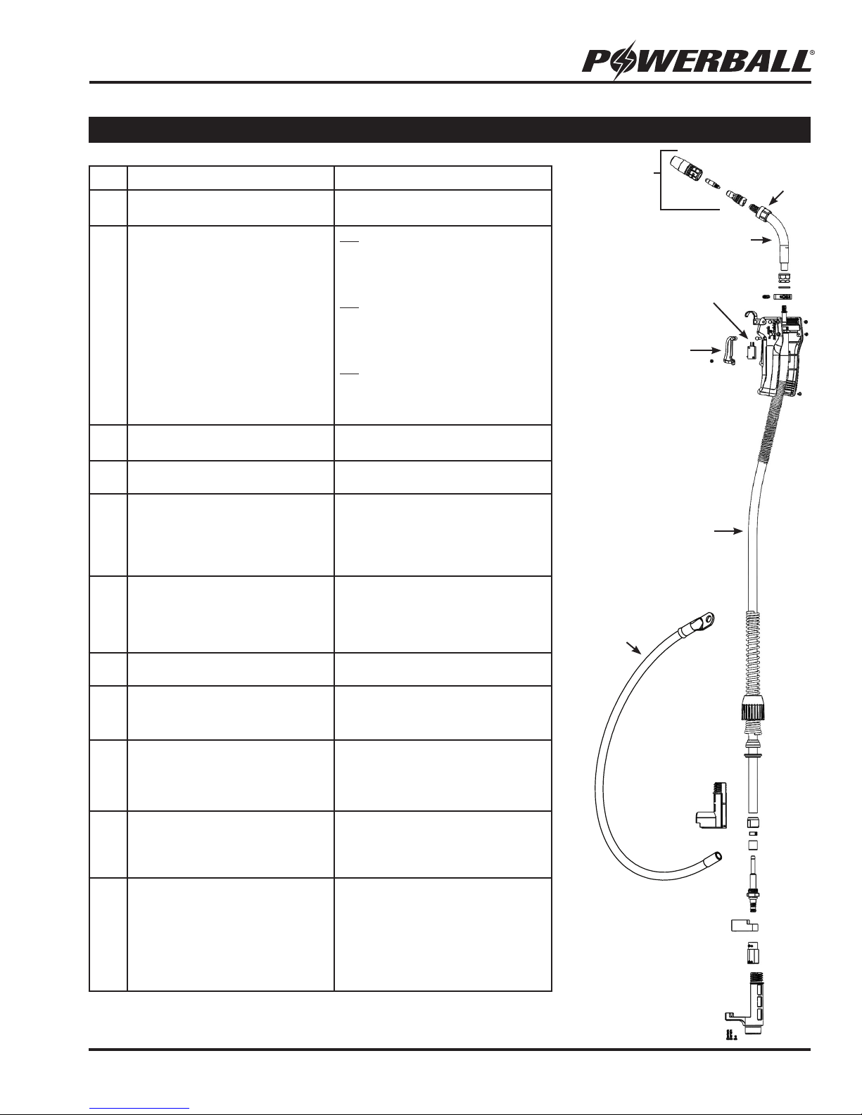
9.0 CONSUMABLES & TORCH ACCESSORIES
WTP‐035‐PB‐1 .035(0.9mm)POWERBALLTIPS‐10pk.
WTP‐035T‐PB‐1 .035(0.9mm)TIGHTTOLERANCEPOWERBALLTIPS‐10pk.
WTP‐040‐PB‐1 .040(1.0mm)POWERBALLTIPS‐10pk.
WTP‐045‐PB‐1 .045(1.2mm)POWERBALLTIPS‐10pk.
WTP‐045T‐PB‐1 .045(1.2mm)TIGHTTOLERANCEPOWERBALLTIPS‐10pk.
WTP‐3/64‐PB‐1 3/64(1.2mm)POWERBALLTIPS‐10pk.
WTP‐3/64A‐PB‐1 3/64(1.2mm)POWERBALLTIPSFORALUMINUMWIRE‐10pk.
WTP‐052‐PB‐1 .052(1.3mm)POWERBALLTIPS‐10pk.
WTP‐062‐PB‐1 .062(1.6mm)POWERBALLTIPS‐10pk.
WTP‐5/64‐PB‐1 5/64(2.0mm)POWERBALLTIPS‐10pk.
WTP‐035‐PB‐3 .035(0.9mm)POWERBALLTIPS‐10pk.
WTP‐040‐PB‐3 .040(1.0mm)POWERBALLTIPS‐10pk.
WTP‐045‐PB‐3 .045(1.2mm)POWERBALLTIPS‐10pk.
WTP‐052‐PB‐3 .052(1.3mm)POWERBALLTIPS‐10pk.
WTP‐062‐PB‐3 .062(1.6mm)POWERBALLTIPS‐10pk.
WTP‐3/32‐PB‐3 3/32(2.4mm)POWERBALLTIPS‐10pk.
WTP‐035‐PB‐5 .035(0.9mm)POWERBALLTIPS‐10pk.
WTP‐035T‐PB‐5 .035(0.9mm)TIGHTTOLERANCEPOWERBALLTIPS‐10pk.
WTP‐040‐PB‐5 .040(1.0mm)POWERBALLTIPS‐10pk.
WTP‐045‐PB‐5 .045(1.2mm)POWERBALLTIPS‐10pk.
WTP‐045T‐PB‐5 .045(1.2mm)TIGHTTOLERANCEPOWERBALLTIPS‐10pk.
WTP‐052‐PB‐5 .052(1.3mm)POWERBALLTIPS‐10pk.
WTP‐062‐PB‐5 .062(1.6mm)POWERBALLTIPS‐10pk.
WTP‐ELD‐PB‐2 POWERBALL®DIFFUSERS‐5pk.
WTP‐ELL‐3545‐10 10FT(3m)TORCHLINERFOR.035‐.045(0.9‐1.2mm)WIRE
WTP‐ELL‐3545‐15 15FT(4.6m)TORCHLINERFOR.035‐.045(0.9‐1.2mm)WIRE
WTP‐ELL‐3545‐25 25FT(7.6m)TORCHLINERFOR.035‐.045(0.9‐1.2mm)WIRE
WTP‐ELL‐45116‐10 10FT(3m)TORCHLINERFOR.045‐1/16(1.2‐1.6mm)WIRE
WTP‐ELL‐45116‐15 15FT(4.6m)TORCHLINERFOR.045‐1/16(1.2‐1.6mm)WIRE
WTP‐ELL‐45116‐25 25FT(7.6m)TORCHLINERFOR.045‐1/16(1.2‐1.6mm)WIRE
WTP‐ELL‐564‐10 10FT(3m)TORCHLINERFOR5/64(2mm)WIRE
WTP‐ELL‐564‐15 15FT(4.6m)TORCHLINERFOR5/64(2mm)WIRE
WTP‐ELL‐564‐25 25FT(7.6m)TORCHLINERFOR5/64(2mm)WIRE
WTP‐ELL‐332‐10 10FT(3m)TORCHLINERFOR3/32(2.4mm)WIRE
WTP‐ELL‐332‐15 15FT(4.6m)TORCHLINERFOR3/32(2.4mm)WIRE
WTP‐ELL‐332‐25 25FT(7.6m)TORCHLINERFOR3/32(2.4mm)WIRE
WTP‐HTL‐3545‐10 10FT(3m)TORCHLINERFOR.035‐.045(0.9‐1.2mm)NON‐FERROUSWIRE
WTP‐HTL‐3545‐15 15FT(4.6m)TORCHLINERFOR.035‐.045(0.9‐1.2mm)NON‐FERROUSWIRE
WTP‐HTL‐45116‐10 10FT(3m)TORCHLINERFOR.045‐1/16(1.2‐1.6mm)NON‐FERROUSWIRE
WTP‐HTL‐45116‐15 15FT(4.6m)TORCHLINERFOR.045‐1/16(1.2‐1.6mm)NON‐FERROUSWIRE
POWERBALL®TORCHLINERS
E‐POWER®STEELLINERSFORFERROUSWIRES
E‐POWER®HI‐TEMPPOLYMERLINERSFORALUMINUM/NON‐FERROUSWIRES
POWERBALL®CONTACTTIPS
PB‐1STYLETIPS,STANDARD
PB‐3STYLETIPSFORHEAVYDUTYAPPLICATIONS
PB‐5STYLETAPEREDTIPSFORNARROWTORCHNOZZLES
POWERBALL®DIFFUSERS
PART# DESCRIPTION MATERIAL
WTP‐ELN‐50B‐TSRB 1/2”(12.7mm)BOTTLENOSE,STANDARDDUTY‐RECESSEDTIP‐5pk. BRASS
WTP‐ELN‐50B‐TSFB 1/2”(12.7mm)BOTTLENOSE,STANDARDDUTY‐FLUSHTIP‐5pk. BRASS
WTP‐ELN‐50B‐TSRC 1/2”(12.7mm)BOTTLENOSE,STANDARDDUTY‐RECESSEDTIP‐5pk. COPPER
WTP‐ELN‐50B‐TSSB 1/2”(12.7mm)BOTTLENOSE,STANDARDDUTY‐PROTRUDINGTIP‐5pk. BRASS
WTP‐ELN‐50B‐TSSC 1/2”(12.7mm)BOTTLENOSE,STANDARDDUTY‐PROTRUDINGTIP‐5pk. COPPER
WTP‐ELN‐50T‐TSRC 1/2”(12.7mm)TAPERED,STANDARDDUTY‐RECESSEDTIP‐5pk. COPPER
WTP‐ELN‐62B‐THFB 5/8”(15.9mm)BOTTLENOSE,HEAVYDUTY‐FLUSHTIP‐5pk. BRASS
WTP‐ELN‐62B‐THFC 5/8”(15.9mm)BOTTLENOSE,HEAVYDUTY‐FLUSHTIP‐5pk. COPPER
WTP‐ELN‐62T‐THFB 5/8”(15.9mm)TAPERED,HEAVYDUTY‐FLUSHTIP‐5pk. BRASS
WTP‐ELN‐62T‐THFC 5/8”(15.9mm)TAPERED,HEAVYDUTY‐FLUSHTIP‐5pk. COPPER
WTP‐ELN‐62T‐THRB 5/8”(15.9mm)TAPERED,HEAVYDUTY‐PROTRUDINGTIP‐5pk. BRASS
WTP‐ELN‐62T‐THRC 5/8”(15.9mm)TAPERED,HEAVYDUTY‐RECESSEDTIP‐5pk. COPPER
WTP‐ELN‐62T‐TSSC 5/8”(15.9mm)TAPERED,HEAVYDUTY‐PROTRUDINGTIP‐5pk. COPPER
POWERBALL®TORCHNOZZLES
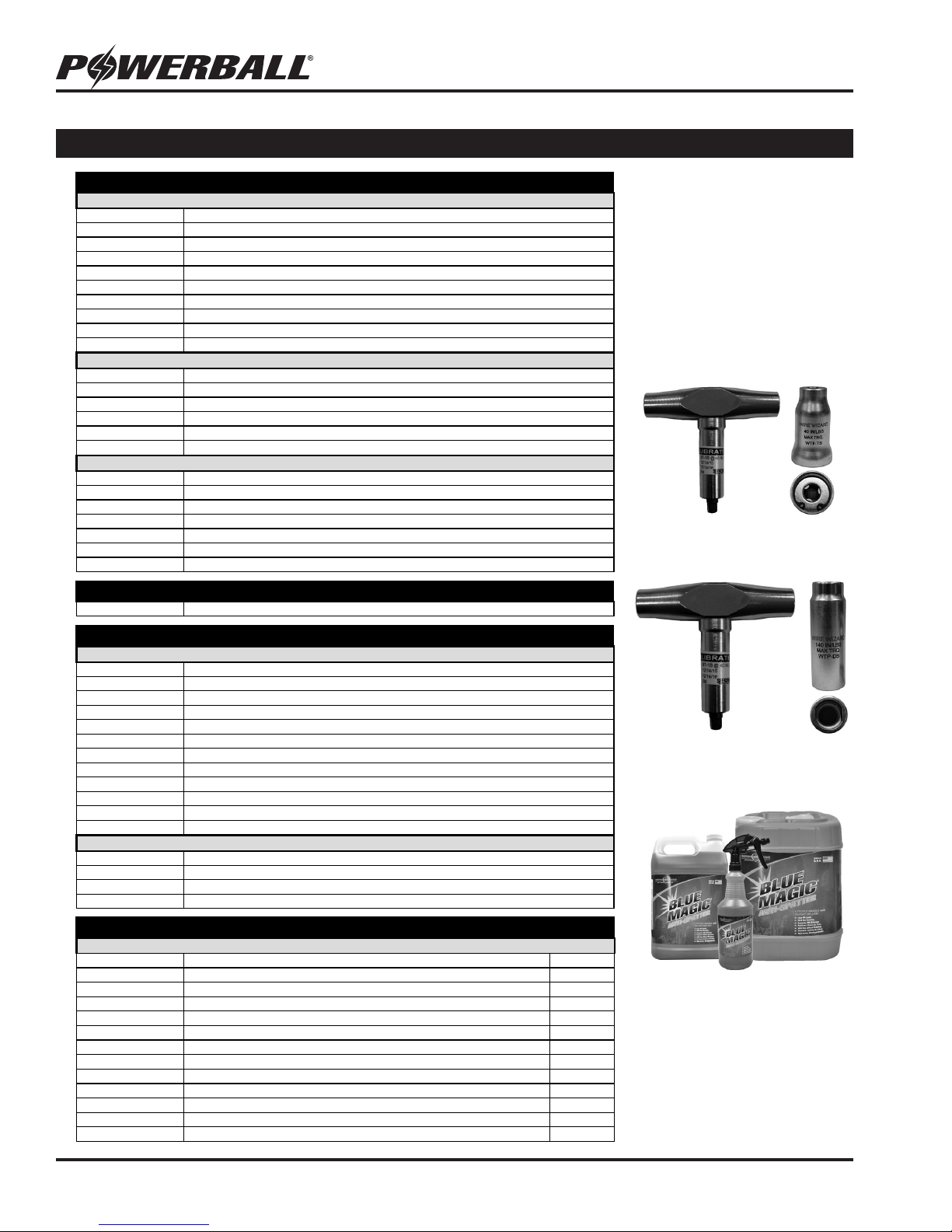
WTP-TS
Tip Socket
WTP-TTW
Calibrated Tip Wrench
(40 in/lbs)
WTP-DTW
Calibrated Diffuser
Wrench (140 in/lbs)
WTP-TS
Diffuser
Socket
Tip & Diffuser Sockets
and Calibrated Wrenches
The 9mm Quick-Grip Torch Tip socket
(1/4”) features an innovative design
with grippers that easily installs and
removes 9mm PowerBall® torch tips.
The 15mm Diffuser Socket (3/8”) is
compatible with all Diffusers with
15mm wrench ats. Saves time and
allows for an accurate torque setting
for consistent contact. Consistent
contact = consistent welds!
Blue Magic®Anti-spatter
Blue Magic® Anti-spatter from Wire
Wizard® Welding Products is highly
recommended for reduced spatter
build-up and adhesion. Specially
formulated for industrial use, this
premium anti-spatter is trusted by
top manufacturers around the globe!
Available through your local welding
product distributor.

11
MIG WELDING GUN OPERATION MANUAL
NOTES
__________________________________________________________
__________________________________________________________
__________________________________________________________
__________________________________________________________
__________________________________________________________
__________________________________________________________
__________________________________________________________
__________________________________________________________
__________________________________________________________
__________________________________________________________
__________________________________________________________
__________________________________________________________
__________________________________________________________
__________________________________________________________
__________________________________________________________
__________________________________________________________
__________________________________________________________
__________________________________________________________
__________________________________________________________
__________________________________________________________
__________________________________________________________
__________________________________________________________
__________________________________________________________

ELCo Enterprises, Inc. • Jackson, Michigan USA • Service & Support: 517-782-8040
www.wire-wizard.com
SAVE THESE INSTRUCTIONS FOR FUTURE REFERENCE
Table of contents
Popular Welding System manuals by other brands

Miller Electric
Miller Electric GENERWELD 130 owner's manual

AOTAI
AOTAI Dura ARC160 instruction manual

SWP
SWP Stealth DIGI-CUT 40PFC MV Operator's manual

Lincoln Electric
Lincoln Electric AIR VANTAGE 500 (AU) Operator's manual

Kemppi
Kemppi MASTERTIG AC/DC 2000 Operation instructions

Forney
Forney 700P operating manual

Snap-On
Snap-On TIG 250 AC-DC Service manual

AUTO ARC
AUTO ARC 190 owner's manual

Würth
Würth PINPULLER SPOT Original operating instructions

Miller Electric
Miller Electric Regency 250 owner's manual

Miller Electric
Miller Electric Spectrum 1251 owner's manual

Abicor Binzel
Abicor Binzel MIG Operating instruction