Instructions
© 2017 Wireless Prime INC. All Rights Reserved. 9
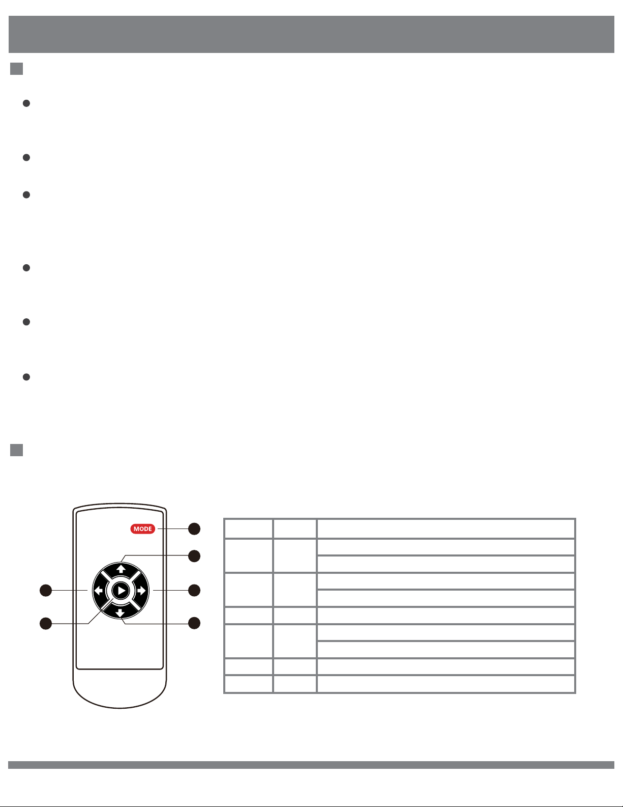
Remote Control Instructions
1
2
3
4
5
6
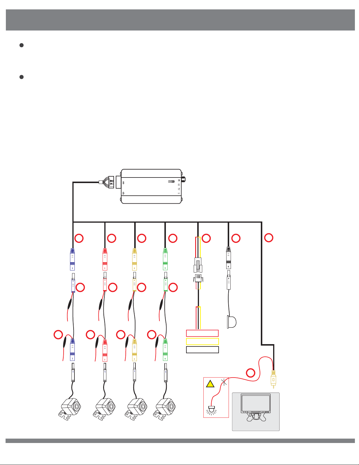
1) Disassemble the panel of the central control unit, and connect the reversing
video channel of the LCD monitor or other display screen(AV in).
2) For IR mode, put the infrared receiver in the proper position.
3) Please connect the anode of the left/right turning signal from the fuse box to
the host wire harness, or from the side mirror turning LED indicator to the
camera side of the extending cable.
4) Connect the power cable to battery supply line and connect the wire harness
to the host device.
5) Fix the host device in the tool cabinet or the space behind the central control
panel.
6) Connect all the cables for the function testing and debugging process, and
assemble the panel back to the control unit.
Host Device Installation Instructions
Key Number Description Function
[1] MODE
Enter setting menu.
In 3D mode, press and hold for 2 seconds to enter 4CH recording mode.
While in menu screen, toggle through icons.
In SVM mode, press to toggle between high beam mode and SVM mode.
In SVM mode, press and hold to enter 360 rotatable menu.
In SVM mode, press and hold to enter reversing gear mode.
In menu screen, select next menu option.
In SVM mode, press and hold to enter 360 rotatable mode.
Confirm selected option.
UP
RIGHT
DOWN
LEFT
CONFIRM
[2]
[3]
[4]
[5]
[6]