WirelessCCTV ALINK-5801A User manual

TDMA Bridge
User Manual
Date: 2013 / 09 / 23
Version: 1.23
D

Copyright
This user’s manual and the software described in it are copyrighted with all rights reserved. No part of
this publication may be reproduced, transmitted, transcribed, stored in a retrieval system, or translated
into any language in any form by any means without the written permission of us.
Preface
About this manual
The purpose to use this manual is for install the wireless Access Point. This manual is including
disposing course and method and helping the customer to solve the unpredictable problem.
The following typographical conventions are used in this purpose:
*** Notice:
This indicates an important Note.
!!! Caution:
This indicates a warning or caution.

Index
CHAPTER 1 INTRODUCTION.....................................................................................................................................5
INTRODUCTION................................................................................................................................................................5
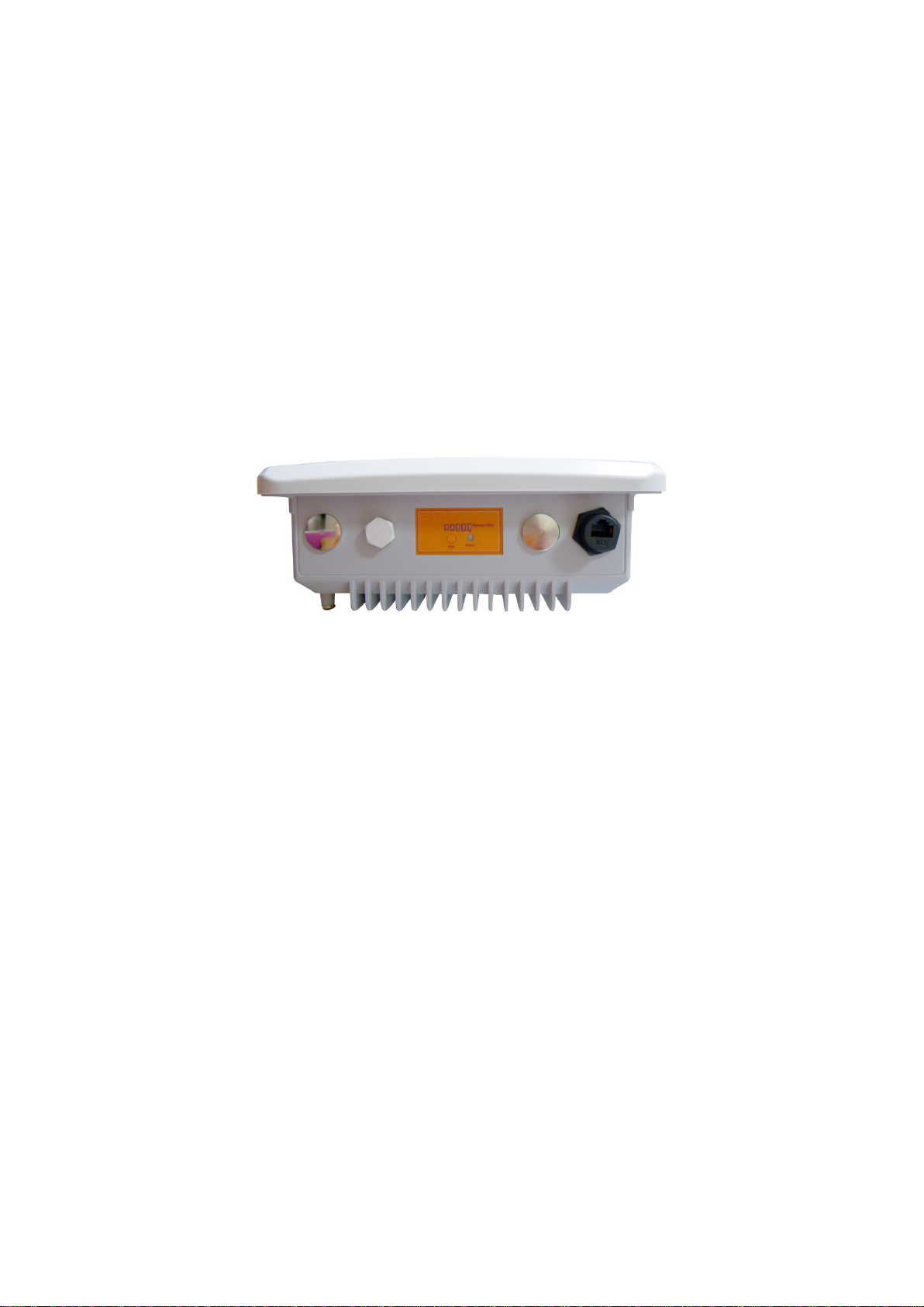
APPEARANCE OF PRODUCT..............................................................................................................................................5
FEATURES AND BENEFITS ................................................................................................................................................5
TYPICALAPPLICATION ....................................................................................................................................................5
CHAPTER 2 HARDWARE INSTALLATION ..............................................................................................................7
SYSTEM REQUIREMENT...................................................................................................................................................7
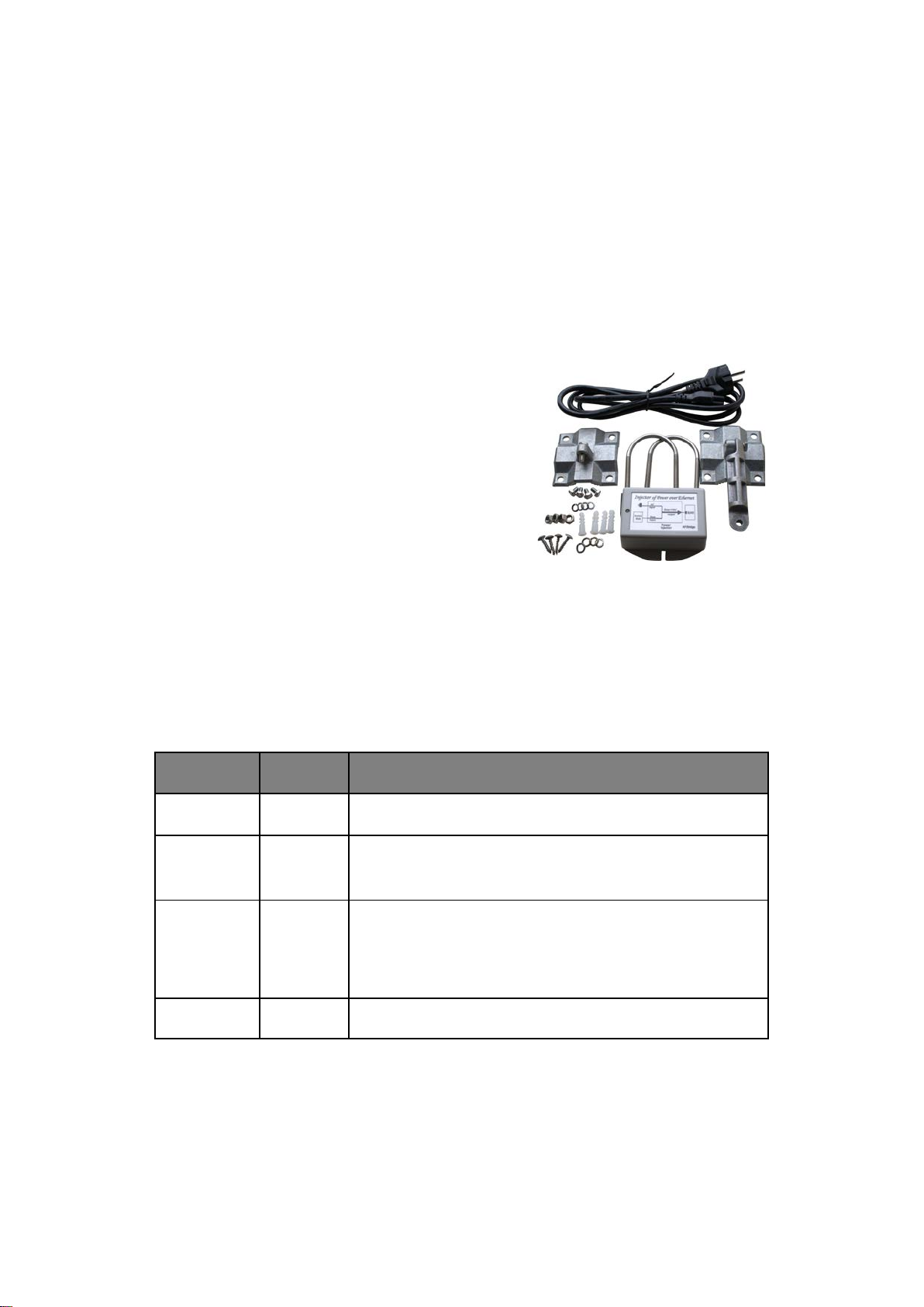
PRODUCT KIT..................................................................................................................................................................7
HARDWARE INSTALLATION..............................................................................................................................................7
LED DESCRIPTIONS ........................................................................................................................................................7
CHAPTER 3 BASIC SETTINGS....................................................................................................................................8
FACTORY DEFAULT SETTINGS..........................................................................................................................................8
HOW TO LOGIN THE WEB-BASED INTERFACE.................................................................................................................8
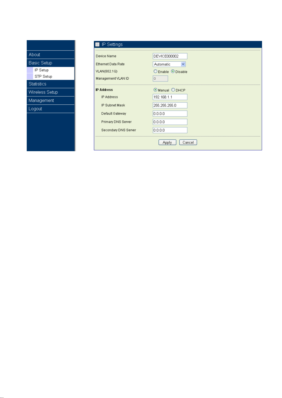
BASIC SYSTEM SETUP .....................................................................................................................................................9
CHAPTER 4 WIRELESS SETTINGS.........................................................................................................................12
BASIC WIRELESS SETTINGS...........................................................................................................................................12
WLAN STATUS .............................................................................................................................................................13
THROUGHPUT................................................................................................................................................................14
STATISTICS ....................................................................................................................................................................14
CHAPTER 5 MANAGEMENT.....................................................................................................................................15
CHANGE PASSWORD......................................................................................................................................................15
REMOTE MANAGEMENT................................................................................................................................................15
REMOTE CONSOLE ........................................................................................................................................................16
UPGRADE FIRMWARE ....................................................................................................................................................17
BACKUP/RESTORE.........................................................................................................................................................18
TIME SERVER ................................................................................................................................................................18
EVENT LOG ...................................................................................................................................................................19
REBOOT.........................................................................................................................................................................20
CHAPTER 6 TROUBLESHOOTING..........................................................................................................................21
FAQ ..............................................................................................................................................................................21
SERVICE SUPPORT .........................................................................................................................................................21

Figure Index
Figure 1 TDMA Bridge ..............................................................................................................5
Figure 2 Point-to-Point .............................................................................................................6
Figure 3 LED Definition ............................................................................................................7
Figure 4 Default Settings..........................................................................................................8
Figure 5 Login Interface ...........................................................................................................9
Figure 6 Device Information.....................................................................................................9
Figure 7 Basic Settings ..........................................................................................................10
Figure 8 STP Setup.................................................................................................................11
Figure 9 parameters of wireless ............................................................................................12
Figure 10 Status......................................................................................................................13
Figure 11 Throughput.............................................................................................................14
Figure 12 Statistics.................................................................................................................14
Figure 13 Password................................................................................................................15
Figure 14 Remote Management.............................................................................................15
Figure 15 PuTTY Configuration 1 ..........................................................................................16
Figure 16 PuTTY Configuration 2 ..........................................................................................16
Figure 17 SSH..........................................................................................................................17
Figure 18 Upgrade Firmware..................................................................................................17
Figure 19 Backup/Restore......................................................................................................18
Figure 20 Time Setting ...........................................................................................................18
Figure 21 Event Log................................................................................................................19
Figure 22 Reboot.....................................................................................................................20

Chapter 1 Introduction
Introduction
Outdoor Bridge is designed for outdoor environment application , the TDMA Bridge work on 2.4GHz,
and is a high-performance outdoor-deployable wireless bridge that provides wireless connectivity among
multiple network location. It provides higher reliability and changeable channel bandwidth, for long
distance point to point connectivity of up to 60km.
Based on powerful TDM technology, it is the best way to ensure higher quality between multi-media
transitions, for example, video, voice and image as well. Also, it is a right solution for telecommunication.
Appearance of Product
Figure 1 TDMA Bridge
Features and Benefits
Support 802.3af PoE (Power over Ethernet)
Support 5/10/20/40 MHz channel bandwidth
Support TDM mechanism, to ensure quality for multi-media application
Support friendly WEB-Based interface for management
Support SNMP remote management
Typical Application
Design for long distance point to point connection. Such as ISP, it is the best choice as low cost, short
construction time for broadband wireless access of enterprise.

Figure 2 Point-to-Point

Chapter 2 Hardware Installation
System Requirement
Installation of Outdoor Bridge unit of TDMA Bridge system requirement:
The IP address of NIC should be the same subnet with the AP, the default IP address of AP is
192.168.1.1
Microsoft Internet Explorer 6 or above.
Product Kit
TDMA Bridge x 1
PoE Injector x 1
Power Code x 1
Mounting Kit x 1
Hardware Installation
The following steps will help you while installing Outdoor Bridge.
LED Descriptions
Definition of LED on the Motherboard:
LED
Status
Description
Power
Blue
Power ON
STATUS Blue
Power on Flash 1 Sec
then OFF
Remote
RSSI Blue
CPE
:
Go around while surveying (not connect yet),
Represent strength of RSSI after connected.
Low ( 1 LED) → High (5 LEDs)
RST
Push 5 seconds then release to reset device
Figure 3 LED Definition

Chapter 3 Basic Settings
Factory Default Settings
We’ll elaborate the TDMA Bridge factory default settings. You can re-acquire these parameters by
default. If necessary, please refer to the “Restore Factory Default Settings”.
Item
Factory Default
Login Information
User Name admin
Password
password
Basic Settings
Device Name DEVICExxxxxx (xxxxxx Represent the last 6 digitals of the MAC address)
Ethernet Data Rate
Automatic
Spanning Tree Protocol Enable
VLAN (802.1Q) Disable
IP Settings
IP Type:Manual
IP Address
:
192.168.1.1
IP Subnet Mask
:
255.255.255.0
Default Gateway
:
0.0.0.0
Primary DNS Server
:
0.0.0.0
Secondary DNS Server: 0.0.0.0
Time Settings
Time Server: [spare]
Time Sever Port: 123
Time Zone: (GMT-08:00)Pacific Time(US & Canada);Tijuana
Wireless Setup
Remote
[Empty]
Cipher
None
Cipher Phrase [Empty]
RF Bandwidth 40MHz
Channel/Frequency 2437 MHz
TX Rate Best
TX Power
Full
Figure 4 Default Settings
How to Login the WEB-Based Interface
The TDMA Bridge provides you with user-friendly Web-based management tool.
Open IE and enter the default IP address (Default: 192.168.1.1) and Login as below:

Figure 5 Login Interface
Enter the username (Default: admin) and password (Default: password) and click “Login”
!!! Caution
IP address of your PC must be the same subnet of device
After login, you can check basic information of device, such as MAC address off device, Firmware
version, etc.
Figure 6 Device Information
Basic System Setup
Into Base Setup, you can do basic settings of device:

Figure 7 Basic Settings
Device Name
Specify the device name, which is composed of no more than 15 characters with (0-9), (A-Z), (a-z) or (-).
Due to support WINS, You can use “Device Name” instead of IP address to access device via WEB
interface. For instance, device named as DEVICE0000FF, you can enter “DEVICE0000FF” in the IE,
then click “ENTER” and WEB page; or use “ping” command to check settings is active or not, such as
ping DEVEICE0000FF.
Ethernet Data Rate
Specify the transmission rate of data, default is Automatic.
Automatic / T-base10Mbps / T-Base100Mbps
IP Address
If you select “Manual”, you have to specify a static IP address, subnet mask, or get IP address from
DHCP.
IP Subnet Mask
Use subnet mask to ensure two devices in the same network.
Default Gateway
Default gateway and DNS server for your local area network which connects to the LAN port.

Primary DNS Sever
First choice of domain name server
Secondary DNS Sever
Second choice of domain name server
Figure 8STP Setup
STP Setup:
The Spanning Tree Protocol allows redundent connections to be created between different LAN
segments for purposes of fault tolerance.
Spanning Tree Protocol (STP) : Default is enable
Bridge Priority : 0 ~ 65535, default is 32768
Hello Time : 1 ~10, default is 2 seconds
Max Age : 6 ~40, default is 20 seconds
Forward Delay : 2 ~30, default is 2 seconds
Wireless Node Aging : 15 ~600, default is 15 seconds

Chapter 4 Wireless Settings
Basic Wireless Settings
Configure basic settings as following:
Figure 9 parameters of wireless
Remote MAC Address:
To specify remote device MAC address. Two devices have to assign MAC address of each other. And
make sure the same parameters of Security, Radio for connection.
Cipher:
There are three modes for encryption of security, NONE, WEP and AES.
Cipher Phrase:
When cipher is WEP、AES, system will generate 128bit dynamic key of WEP or AES.
RF Bandwidth
Decide bandwidth of Radio Frequency. Including 5 / 10 / 20 / 40 MHz (5 / 10MHz Coming soon)
Channel / Frequency
To select suitable channel and frequency from pull down menu, such as 2,437MHz and auto channel.

TX Rate
Normally choice transmission rate as “Best”, system will adapt best rate for real environment.
Including 64QAM 3/4, 64QAM 2/3, 16QAM 3/4, 16QAM 1/2, QPSK 3/4, QPSK 1/2, BPSK 3/4, BPSK 1/2
TX Power
Transmission power, 1/2 of transmission power equals to 3dB. Including Full / Half / Quarter / Eighth /
Min
Half: -3 dB
Quarter: -6 dB
Eighth: -9 dB
Min: -12 dB
WLAN Status
In this page, it can show remote bridge RSSI for local bridge and local bridge RSSI for remote bridge.
We can decide the best direction of antenna from following steps:
1. We check the RSSI only in one side. (We call it local side.)
2. Fix remote side antenna, and adjust local side antenna. In local side, check the “RSSI” first, to find a
best RSSI and then fix the local antenna.
3. Adjust the Remote antenna, to find the Best Remote RSSI, and then fix the remote antenna.
4. If “RSSI” is changed, and worse than before, adjust local antenna again to get a best one and fix
local antenna.
5. If “Remote RSSI” is changed and worse, adjust remote antenna again.
6. Follow the same ways to get a better RSSI and Remote RSSI value. And Fix both side antennas.
Figure 10 Status

Throughput
Throughput show graphs which continuously represents the current data traffic on the Wireless interface.
The chart scale and throughput dimension (Bps, Kbps, Mbps) changes dynamically according to the
throughput value. Throughput statistics is updated automatically.
Figure 11 Throughput
Statistics
Display wired and wireless statistics of packets including transmitted and received packets, Uncast,
Broadcast, Multicast and total Packets.
Figure 12 Statistics

Chapter 5 Management
Change Password
Via “Change Password”,you can modify password for WEB management.
Figure 13 Password
You have to enter “Current Password” first (default is password), then can change new password,
maximum length of password is 63 bytes. Choice “Restore Default Password”, it will restore password as
default setting as “password”.
Remote Management
Figure 14 Remote Management

Remote Console
The TDMA Bridge supports CLI management, which could be accessed by Secure Shell
(SSH). It is recommended PuTTY be used to login. Download it
from http://www.putty.org/ for free. The minimum system requirement for using PuTTY is
Windows 95, 98, ME, NT, 2000, XP and Vista on Intel x86.
Follow the steps below to implement:
Once the program is downloaded, open up by double-clicking. Note that before using
PuTTY, be sure you are able to connect to the Outdoor Bridge.
Enter IP Address of TDMA Bridge (Default: 192.168.1.1), Port (22) and check SSH as
connection type;
Figure 15 PuTTY Configuration 1
From “Connection” in the left menu bar, click “SSH”; select “2” as “Preferred SSH
protocol version”; make “3DES” the top position in “Encryption cipher selection policy”;
Figure 16 PuTTY Configuration 2

Click “Open”, a window as below will popup:
Figure 17 SSH
Enter the user name and password (Default user name/ password: admin/password)
respectively, you will see “DEVICE123456>”, which is the name of TDMA Bridge;
Upgrade Firmware
Via WEB interface to upgrade firmware:
Figure 18 Upgrade Firmware
Open “Upgrade Firmware” page。
Click “browse” to select new “Firmware” .
Click “Upload” send Firmware to device.
After checked Firmware by system, it starts to upgrade firmware, and will back to Login page after
firmware upgrade successful, otherwise system will show you the reason why it failed.
!!! Caution
Do NOT cut the power off during upgrade, otherwise the system may crash!

Backup/Restore
It would be better to backup settings of device after it work fine, so that you can recover settings quickly
when something go wrong.
Figure 19 Backup/Restore
Open “Backup/Restore” page,click “Backup”, it will pop up a dialog for input path and
filename, such as F:\device.cfg, and it will save “device.cfg” in the local disk after that.
Open “Backup/Restore” page, click “Browser”,It will pop up a dialog to choice what file you want to
restore, such as “F:\device.cfg”, then click “Retrieve, the settings of the file will be restored back to
device, and it will active for the device after auto reboot.
Open “Backup/Restore” page, click “Restore”, device will back to factory settings, or push “Default”
button as device active, then it will back to factory settings after Alarm LED stop flash.
Time Server
Figure 20 Time Setting

Time Server
Follow NTP protocol, and synchronize with Time Server.
Time Server Port
Time Server port, default is 123.
Time Zone
Select your time zone, default is (GMT-08:00)Pacific Time(US & Canada); Tijuana.
Adjust for Daylight Saving Time
Select adjust for daylight saving time or not, default is disabled.
Event Log
Event log can show you the event of device, for example, connect, disconnect, reboot of Base station, or
something change about settings.
Figure 21 Event Log
Enable Syslog
Select open Syslog or not.

Syslog Server IP Address
Assign IP address of syslog server
Syslog Server Port Number
Syslog server’s Port.
Event Log Windows
Check event log from the windows.
Save As
Click the button will save even logs to the directory as you assigned.
Refresh
Click the button can display logs from the “Event Log Windows”
Reboot
When you need to reboot the device, you can click the “yes” button and the click “Apply” it will reboot.
Figure 22 Reboot
Table of contents
Popular Network Hardware manuals by other brands

Patton electronics
Patton electronics OnSite 1052 Series quick start guide

Omron
Omron CJ1W-ETN11 Operation manual

Amped Wireless
Amped Wireless AV3000 Setup guide

ADTRAN
ADTRAN Total Access 300 Series Installation and maintenance guide

CORNING
CORNING CCH-CS quick start guide

Allied Telesis
Allied Telesis iMap 9100 datasheet