Wisenet TEC-F Series User manual

INS_TE(C,U)-FX 08/12/19 PAGE 1
INSTALLATION AND OPERATION MANUAL TE(C,U)-F SERIES
TE(C,U)-F Series
ETHERNET OVER COPPER EXTENDER WITH
PASS-THROUGH POE UP TO 15 WATTS
The Ethernet over copper line supports up to sixteen channels of 10/100Mbps
Ethernet with Pass-through PoE over twisted pair cable (CAT-5, UTP), or over
coaxial cable. The single channel units may be powered by a PoE switch or the
included power supply. Four and sixteen channel units operate from local power.
These units provide the ultimate flexibility for extending a powered device (PD)
over long distance copper. DIP switches are provided for user-selection of local or
remote, 10 or 100Mbps, and 1 pair or 4 pair (UTP) settings.
The TE(C,U)-F16 are 1RU rack mountable units. The TE(C,U)-F04 units are
interchangeable between stand-alone or card mount configurations, or may be DIN-
rail mounted by the addition of model SBP-UDR.The TE(C,U)-F01 units are stand-
alone, or may be DIN-rail mounted by the addition of model SBP-UDR adaptor.
This manual serves the following
Model Names:
TEC-F01
TEC-F04
T EC - F16
TEU-F01
TEU-F04
T EU - F16

INS_TE(C,U)-FX 08/12/19 PAGE 2
INSTALLATION AND OPERATION MANUAL TE(C,U)-F SERIES
FIGURE 1 – TEC-F01 SINGLE CHANNEL COAX UNIT
FIGURE 3 – TEU-F01 SINGLE CHANNEL UTP UNIT
FIGURE 2 – TEC-F01 SINGLE CHANNEL COAX UNIT
FIGURE 4 – TEU-F01 SINGLE CHANNEL UTP UNIT
EXT DISTANCE
EXT DISTANCE
ETHERNET
ETHERNET
Power: Operates on PoE power
OR 9 to 36 VDC
OR 24 VAC
Power Consumption: 1.5 W
Power: Operates on PoE power
OR 9 to 36 VDC
OR 24 VAC
Power Consumption: 1.5 W
Black (AC or DC–)
Black w/ White
Stripe (AC or DC+)
Black (AC or DC–)
Black w/ White
Stripe (AC or DC+)
Local/Remote push button
See Installation Instructions,
Step 3
Local/Remote DIP switch
10/100 data rate DIP switch
Wire pair DIP switch
10/100 data rate DIP switch
Local/Remote DIP switch
UP
DOWN
DOWN
UP
Switch UP DOWN
Local/Remote Remote Local
10/100 10 Mbps 100 Mbps
See Installation Instructions for more information
Switch UP DOWN
Local/Remote Remote Local
10/100 10 Mbps 100 Mbps
Wire Pair 4 Pair 1 Pair
See Installation Instructions for more information

INS_TE(C,U)-FX 08/12/19 PAGE 3
INSTALLATION AND OPERATION MANUAL TE(C,U)-F SERIES
FIGURE 3 – TEC-F04 FOUR CHANNEL SURFACE OR RACK MOUNT COAX UNIT
FIGURE 4 – TEC-F04 FOUR CHANNEL SURFACE OR RACK MOUNT COAX UNIT
CH1 EXT
DISTANCE
CH1 ETHERNET
CH2 EXT
DISTANCE
CH2 ETHERNET
CH3 EXT
DISTANCE
CH3 ETHERNET
CH4 EXT
DISTANCE
CH4 ETHERNET
Operating Power: 9 to 15 VDC
Power Consumption: 5W
Black (DC-)
Black w/ White
Stripe (DC+)
Local/Remote push button
See Installation Instructions,
Step 3
10/100 data rate
DIP switch
See Installation
Instructions, Step 1
Local/Remote DIP switch
See Installation Instructions,
Step 3

INS_TE(C,U)-FX 08/12/19 PAGE 4
INSTALLATION AND OPERATION MANUAL TE(C,U)-F SERIES
FIGURE 5 – TEU-F04 FOUR CHANNEL SURFACE OR RACK MOUNT UTP UNITS
FIGURE 6 – TEU-F04 FOUR CHANNEL SURFACE OR RACK MOUNT UTP UNITS
CH1 EXT
DISTANCE
CH1 ETHERNET
CH2 EXT
DISTANCE
CH2 ETHERNET
CH3 EXT
DISTANCE
CH3 ETHERNET
CH4 EXT
DISTANCE
CH4 ETHERNET
Operating Power: 9 to 15 VDC
Power Consumption: 5W
Black (DC–)
Black w/ White
Stripe (DC+)
Local/Remote DIP switch
See Installation Instructions, Step 3
Wire pair DIP switch
See Installation Instructions, Step 2
Data rate DIP switch
See Installation Instructions, Step 1

INS_TE(C,U)-FX 08/12/19 PAGE 5
INSTALLATION AND OPERATION MANUAL TE(C,U)-F SERIES
CH4 EXT DISTANCE
CH12 EXT DISTANCE
CH5 ETHERNET
CH13 ETHERNET
CH8 EXT DISTANCE
CH16 EXT DISTANCE
CH1 ETHERNET
CH9 ETHERNET
CH3 EXT DISTANCE
CH11 EXT DISTANCE
CH6 ETHERNET
CH14 ETHERNET
CH7 EXT DISTANCE
CH15 EXT DISTANCE
CH2 ETHERNET
CH10 ETHERNET
CH2 EXT DISTANCE
CH10 EXT DISTANCE
CH7 ETHERNET
CH15 ETHERNET
CH6 EXT DISTANCE
CH14 EXT DISTANCE
CH3 ETHERNET
CH11 ETHERNET
CH1 EXT DISTANCE
CH9 EXT DISTANCE
CH8 ETHERNET
CH16 ETHERNET
CH5 EXT DISTANCE
CH13 EXT DISTANCE
CH4 ETHERNET
CH12 ETHERNET
FIGURE 7 – TEC-F16 MULTICHANNEL RACK COAX UNITS
Data rate DIP switch
See Installation
Instructions, Step 1
Data rate DIP switch
See Installation
Instructions, Step 1
Data rate DIP switch
See Installation
Instructions, Step 1
Data rate DIP switch
See Installation
Instructions, Step 1
Operating Power: 9 to 15 VDC
Power Consumption: 20W
Black (DC–)
Black w/ White Stripe (DC+)

INS_TE(C,U)-FX 08/12/19 PAGE 6
INSTALLATION AND OPERATION MANUAL TE(C,U)-F SERIES
CH4 EXT DISTANCE
CH12 EXT DISTANCE
CH5 ETHERNET
CH13 ETHERNET
CH8 EXT DISTANCE
CH16 EXT DISTANCE
CH1 ETHERNET
CH9 ETHERNET
CH3 EXT DISTANCE
CH11 EXT DISTANCE
CH6 ETHERNET
CH14 ETHERNET
CH7 EXT DISTANCE
CH15 EXT DISTANCE
CH2 ETHERNET
CH10 ETHERNET
CH2 EXT DISTANCE
CH10 EXT DISTANCE
CH7 ETHERNET
CH15 ETHERNET
CH6 EXT DISTANCE
CH14 EXT DISTANCE
CH3 ETHERNET
CH11 ETHERNET
CH1 EXT DISTANCE
CH9 EXT DISTANCE
CH8 ETHERNET
CH16 ETHERNET
CH5 EXT DISTANCE
CH13 EXT DISTANCE
CH4 ETHERNET
CH12 ETHERNET
FIGURE 8 – TEU-F16 MULTICHANNEL RACK UTP UNITS
Data rate DIP switch
See Installation
Instructions, Step 1
Data rate DIP switch
See Installation
Instructions, Step 1
Data rate DIP switch
See Installation
Instructions, Step 1
Data rate DIP switch
See Installation
Instructions, Step 1
Wire pair DIP switch
See Installation
Instructions, Step 2
Wire pair DIP switch
See Installation
Instructions, Step 2
Wire pair DIP switch
See Installation
Instructions, Step 2
Wire pair DIP switch
See Installation
Instructions, Step 2
Operating Power: 9 to 15 VDC
Power Consumption: 20W
Black (DC–)
Black w/ White Stripe (DC+)

INS_TE(C,U)-FX 08/12/19 PAGE 7
INSTALLATION AND OPERATION MANUAL TE(C,U)-F SERIES
APPLICATION DIAGRAMS
Note: Coaxial applications use TEC modules; UTP applications use TEU modules.
PoE Pass-Through Mode
Non-PoE Mode
Multichannel Non-PoE Application
Multichannel PoE Application
IMPORTANT NOTE. PLEASE READ. The applications are
shown as general representations only and are not intended
to show detailed network topologies. Your actual network
will differ, requiring changes or perhaps additional network
equipment to accommodate the systems as illustrated.
Please contact Technical Support to discuss your specific
requirements.
PoE
Ethernet Switch
or Midspan
Local Remote
TE(C,U)-F01 TE(C,U)-F01 PoE Camera
Ethernet
Switch
Local Remote
Power Power Power
TE(C,U)-F01 TE(C,U)-F01 IP Camera
Ethernet
Switch
Local Remote
TE(C,U)-F04
TE(C,U)-F16
TE(C,U)-F01
TE(C,U)-F01
TE(C,U)-F01
TE(C,U)-F01
Power
IP Camera
Power Power
IP Camera
Power Power
IP Camera
Power Power
IP Camera
Power Power
IP Camera
Power Power
IP Camera
Power
PoE Camera
PoE Camera
PoE Camera
PoE Camera
PoE Camera
PoE Camera
PoE Camera
Local Remote
Power
TE(C,U)-F16
TE(C,U)-F04
TE(C,U)-F04
TE(C,U)-F01
TE(C,U)-F01
TE(C,U)-F01
TE(C,U)-F01
TE(C,U)-F01
Power
Power
PoE
Ethernet Switch
or Midspan
Ethernet Connection
PoE Power
Extended Connection

INS_TE(C,U)-FX 08/12/19 PAGE 8
INSTALLATION AND OPERATION MANUAL TE(C,U)-F SERIES
INSTALLATION INSTRUCTIONS
1 - SET 10/100 SWITCH
Locate the 10/100 data rate DIP switch on the unit.
Set the data rate according to bandwidth required.
NOTE: The data rate must be set the same on both the local and remote units.
2 - SET WIRE PAIR DIP SWITCHES (UTP MODELS ONLY, FOR COAX MODELS SKIP TO STEP 3)
Locate the wire pair DIP switch on the unit.
Set the pair according to number of twisted wire pairs used (1 or 4).
NOTE: The number of pairs selected must be set the same on both the local and remote units.
PoE Pass-Through mode is only available in 4-pair mode and requires a PD device connected to
the remote unit to operate.
3 - SET LOCAL/REMOTE SWITCHES (1 AND 4 CHANNEL UNITS ONLY, FOR RACK UNITS SKIP TO STEP 4)
Locate the Local/Remote Dip switch and set to “LC” at the head end or “RM” at the camera end.
Locate the Local/Remote push button switch (coax units only), and set to the same setting as the dip switch.
The TE(C,U)-F16 units are preconfigured as Local devices.
4 - CONNECT EXTENDED WIRING
Connect Extended Distance Port to field wiring.
5 - CONNECT NETWORK WIRING
Using CAT5/5e cabling, connect Local unit to network and Remote unit to camera.
6 - CONNECT POWER
Connect power to unit per the following table:
Power Connections per Use Case
Unit Local Power Pass-Through PoE
TE(C,U)-F01 9 to 36 VDC or 18 to 32 VAC No external power required
TE(C,U)-F04 9 to 15 VDC (9 VDC†when in a SBP-C03 or SBP-C14 rack)
TE(C,U)-F16 9 to 15 VDC
†Contact pre-sales support, or refer to the appropriate installation and operation manual when configuring and specifying power for a deployment.
7 - VERIFY FUNCTIONALITY
See LED table below and Troubleshooting Guide if corrective action is needed. See figures beginning on page 6 for LED
configurations for each model.
Indicating LEDs
PWR Ethernet Link Ethernet Activity EXT LNK
GREEN Power Applied – Activity Detected 10Mbps
YELLOW –Link Established –100Mbps
OFF Power Off No Link No Activity No Link
Ethernet
Activity
Ethernet
Link
EXT Link Power
TEU-F01 Only
For 1-pair mode, use the first
pair of pins (pins 1 and 2) of the
“Extended Ethernet” RJ-45 port.

INS_TE(C,U)-FX 08/12/19 PAGE 9
INSTALLATION AND OPERATION MANUAL TE(C,U)-F SERIES
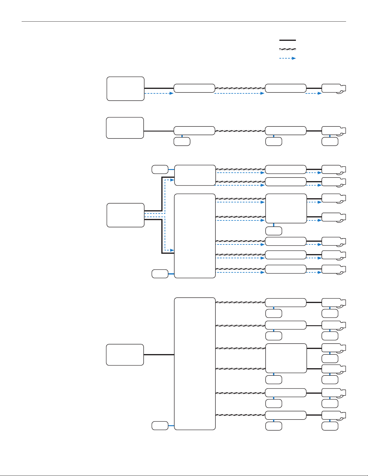
1 Mixed PoE and Non-PoE systems can be implemented.
2 All Non-PoE systems require local power.
3 PoE powered operation requires that a PoE Camera be connected, and that the camera power requirements are understood.
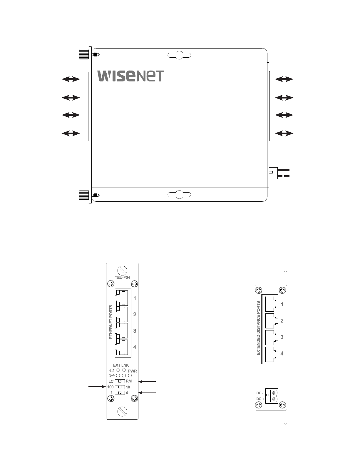
4 Multiple Channel units (TE(C,U)-F04, TE(C,U)-F16) require 9 to 15 VDC for proper operation. The TE(C,U)-F04 can be used in a
SBP-C14 or SBP-C03.
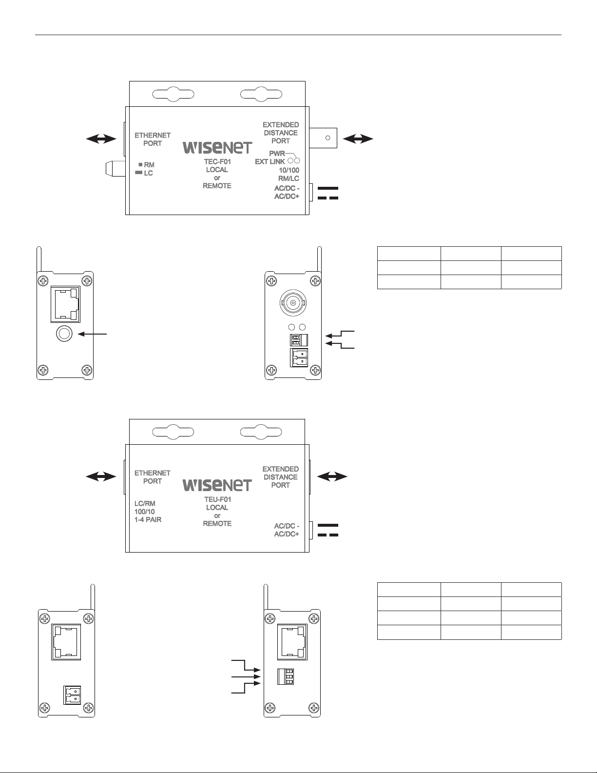
5 Single Channel units (TE(C,U)-F01) require power for all Non-PoE applications. Local power can be used in PoE application to
minimize PoE consumption.
6 Lower data rates generally provide longer operating distances.
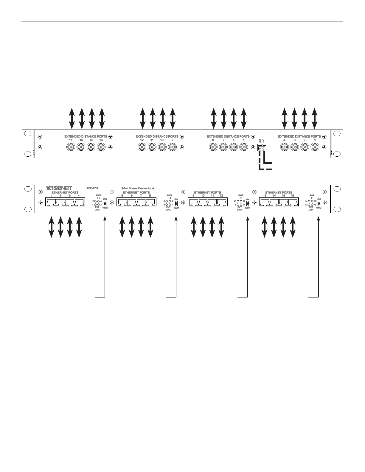
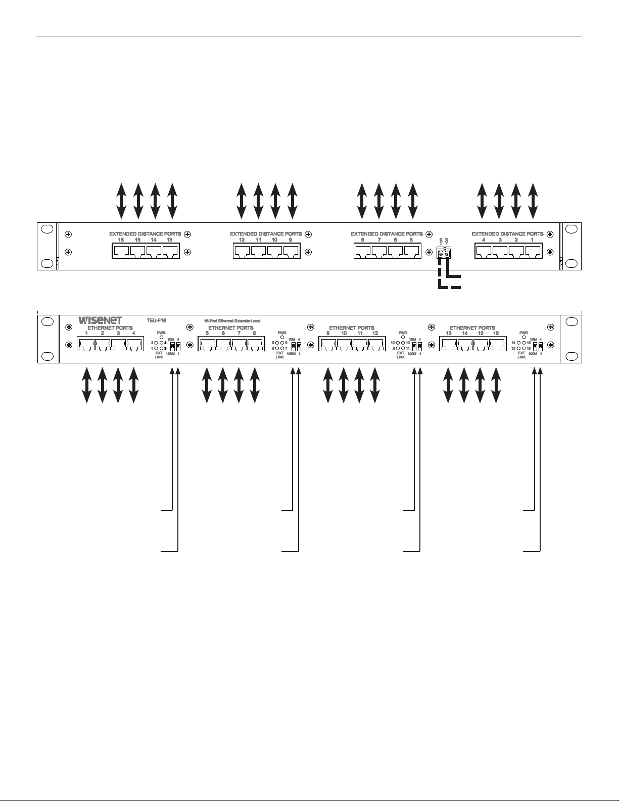
7 Rack units (TE(C,U)-F16) are pre-configured for Local (LC) and have no configurable Local/Remote switch. Any unit connected to one
of these rack units via an extended distance port must be configured as Remote (RM) for proper operation.
APPLICATION NOTES
APPROXIMATE MAXIMUM EXTENDED DISTANCES1
TROUBLESHOOTING GUIDE
Problem Steps to Take
Indicating LEDs not lighting Non-PoE: Check that power is properly applied to the unit
PoE: Check that PoE camera is connected, PoE source is enabled.
No Communication Check Ethernet Link LEDs, Extended Link LEDs, All Connections, Local/Remote and 10/100 switches are set properly. Verify that Local
units are installed at the head end and that Remote units are installed in the field.
Bad Video Make sure Data Rate Switch is set properly, and the extended distance is within specifications (see Table “Approximate
Maximum Extended Distances”).
PoE Not Supplied to PD Make sure camera is IEEE 802.3af rated, PoE Source switch is set properly, and the extended distance is within specifications (see Table
“Approximate Maximum Extended Distances”).
Units not reaching
estimated max distances
over COAX or CAT5/UTP
Check extended distance cable and connections. Try connection on a short cable to eliminate possibility of faulty cabling.
Check that the extended distance wire is connected to Extended Distance Port.
Verify that there is no additional equipment (e.g. surge protector) on the Extended Link. The cable should be continuous from end to end,
with no active components.
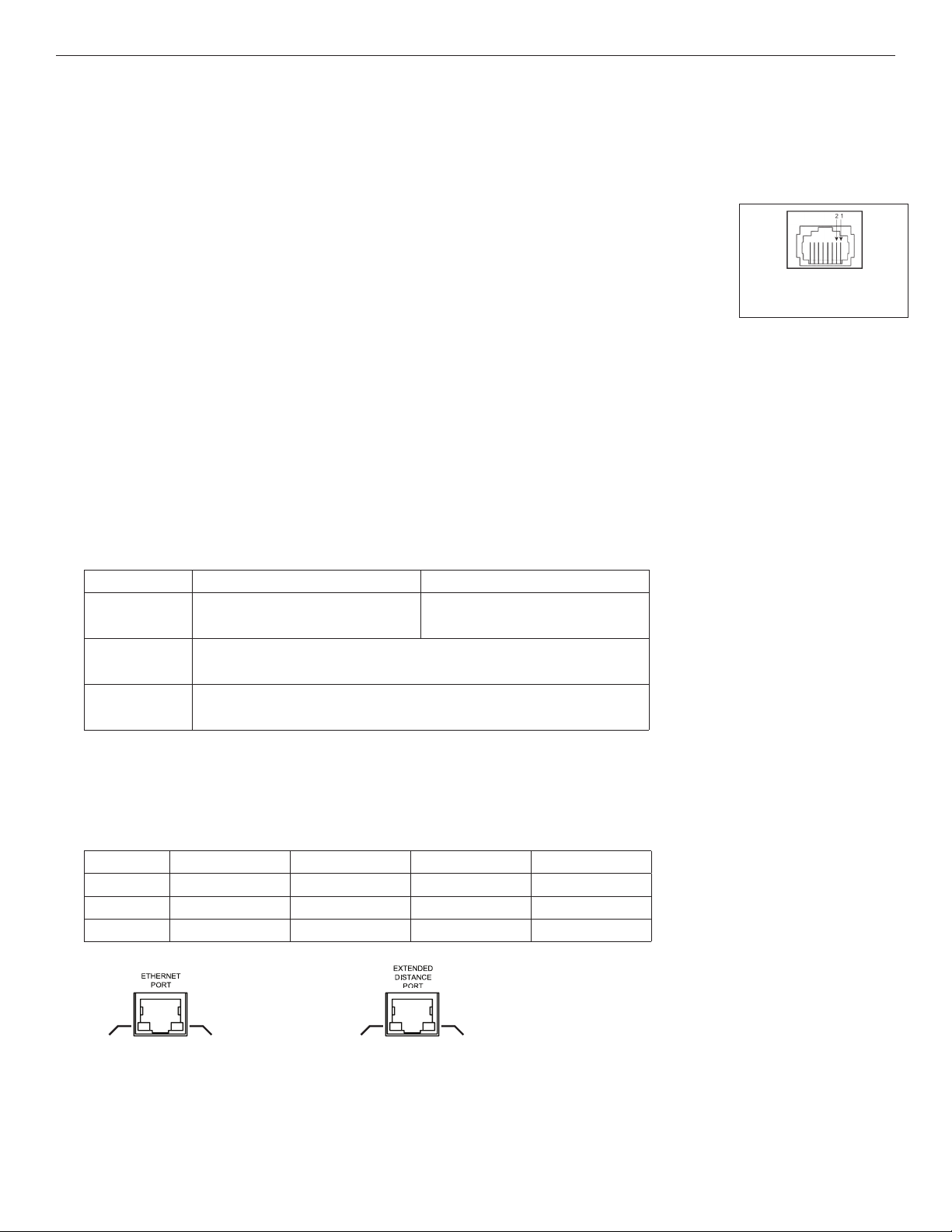
Media COAX - RG59/U UTP - 4 pair UTP - 1 pair
Data Rate 10M 100M 10M 100M 10M 100M
Source Power 15W 30W 15W 30W 15W 30W 15W 30W N/A
Non-PoE Max.Distance15,000 ft
1,524 m
2,000 ft
610 m
3,000 ft
914 m
2,000 ft
610 m
3,000 ft
914 m
1,000 ft
305 m
PoE CLASS2 (6.5W)13,000 ft
914 m
3,000 ft
914 m
2,000 ft
610 m
2,000 ft
610 m
3,000 ft
914 m
3,000 ft
914 m
2,000 ft
610 m
2,000 ft
610 m N/A
PoE CLASS3 (13W)1750 ft
228 m
850 ft
259 m
750 ft
228 m
850 ft
259 m
750 ft
228 m
850 ft
259 m
750 ft
228 m
850 ft
259 m N/A
[1] Distance figures are based on a 50 V PSE PoE power source, and external power supplies for the extenders. Distance figures are obtained using
in-house testing mirroring installations. Factors such as coaxial and copper cable quality, the number of connectors and splices in the cable run,
the use of PoE, and environmental conditions encountered within the installation might affect the actual transmission distance and should be
taken into consideration. Due to advanced negotiation signaling required in IEEE802.3at applications, pass-through applications are limited to
IEEE802.3af PD devices only. When using UTP models Pass-Through PoE is only possible in 4-pair mode.

INS_TE(C,U)-FX 08/12/19 PAGE 10
INSTALLATION AND OPERATION MANUAL TE(C,U)-F SERIES
FIGURE A
Dimensions are for a small size module
FIGURE B
Dimensions are for a standard module
FIGURE C
Dimensions are for a 19″Rack Unit
8.38cm
[3.3in]
2.7cm
[1.06in]
4.19cm
[1.65in]
0.8cm
[0.31in]
0.4cm
[0.16in]
0.62cm
[0.24in]
6.37cm
[2.50in]
13.2cm
[5.2in]
11.9cm
[4.7in]
15cm
[5.9in]
7.5cm
[2.9in]
0.63cm
[0.25in]
2.75cm
[1.1in]
44.45cm
[17.50in]
48.26cm
[19.0in]
15.44cm
[6.08in]
1.9cm
[0.75in]
4.37cm
[1.72in]
1.9cm
[0.75in]
PRODUCT DIMENSIONS

INS_TE(C,U)-FX 08/12/19 PAGE 11
INSTALLATION AND OPERATION MANUAL TE(C,U)-F SERIES
INSTALLATION CONSIDERATIONS
These units are supplied as Standalone/Rack mounted module. Units should be installed in dry locations protected from extremes of temperature and
humidity.
IMPORTANT SAFEGUARDS:
A) Elevated Operating Ambient - If installed in a closed or multi-unit rack assembly, the operating ambient temperature of the rack environment may be greater than
room ambient. Therefore, consideration should be given to installing the equipment in an environment compatible with the maximum ambient temperature (Tma)
specified by the manufacturer.
B) Reduced Air Flow - Installation of the equipment in a rack should be such that the amount of air flow required for safe operation of the equipment is not compromised.
SBP-C14 / SBP-C03 CARD CAGE RACKS
CAUTION: Although the units are hot-swappable and may be installed without turning power off to the rack, Hanwha recommends that the power
supply be turned off and that the rack power supply is disconnected from any power source. Note: Remove electrical connector before installing in
card cage rack.
1.Make sure that the card is oriented right side up, and slide it into the card guides in the rack until the edge connector at the back of the card seats
in the corresponding slot in the rack’s connector panel. Seating may require thumb pressure on the top and bottom of the card’s front panel.
CAUTION: Take care not to press on any of the LEDs.
2. Tighten the two thumb screws on the card until the front panel of the card is seated against the front of the rack.
WARNING: Unit is to be used with a Listed Class 2 power supply.
This manual suits for next models
7
Table of contents