WISKA VARITAIN PushIn User manual

OPERATING INSTRUCTIONS
SOCKET SYSTEM FOR COOLING
CONTAINERS
VARITAIN PushIn

About these instructions 50103430000_Varitain-PI(Ver1.4)Rev 01122018E.docx
2
Contents
1. ABOUT THESE INSTRUCTIONS................................................ 3
1.1 Symbols and guidance signs in these instructions................3
1.2 Who are these instructions for?.............................................3
2. SYSTEM DESCRIPTION ............................................................. 4
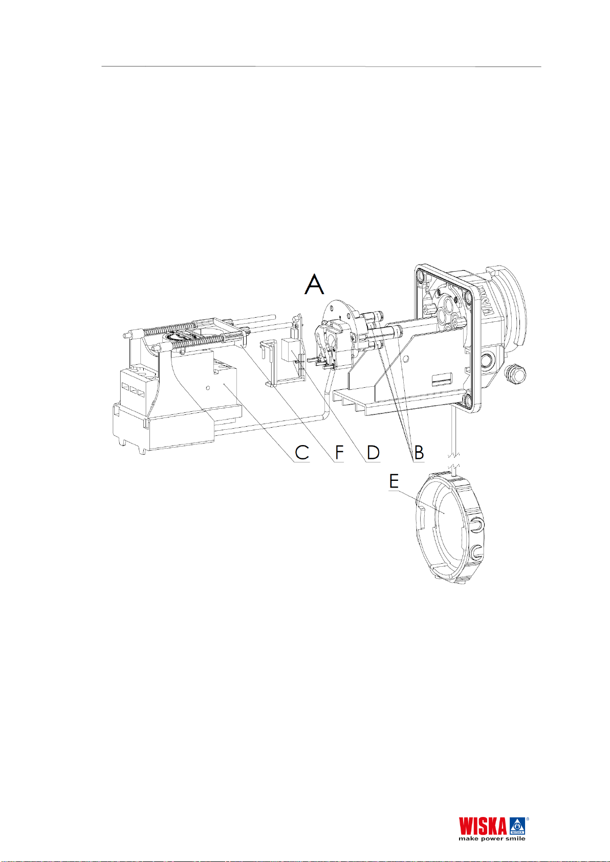
3.1 The system components........................................................ 5
3. DESCRIPTION............................................................................. 6
4.1 Casing....................................................................................6
4.2 CEE socket insert .................................................................. 6
4.3 LED unit ................................................................................. 6
4.4 Locking system ...................................................................... 7
4.5 Circuit-breaker .......................................................................8
4.6 Connection terminals............................................................. 8
4. REPAIR AND MAINTENANCE ................................................... 9
5.1 Maintenance .......................................................................... 9
5.2 Repair..................................................................................... 9
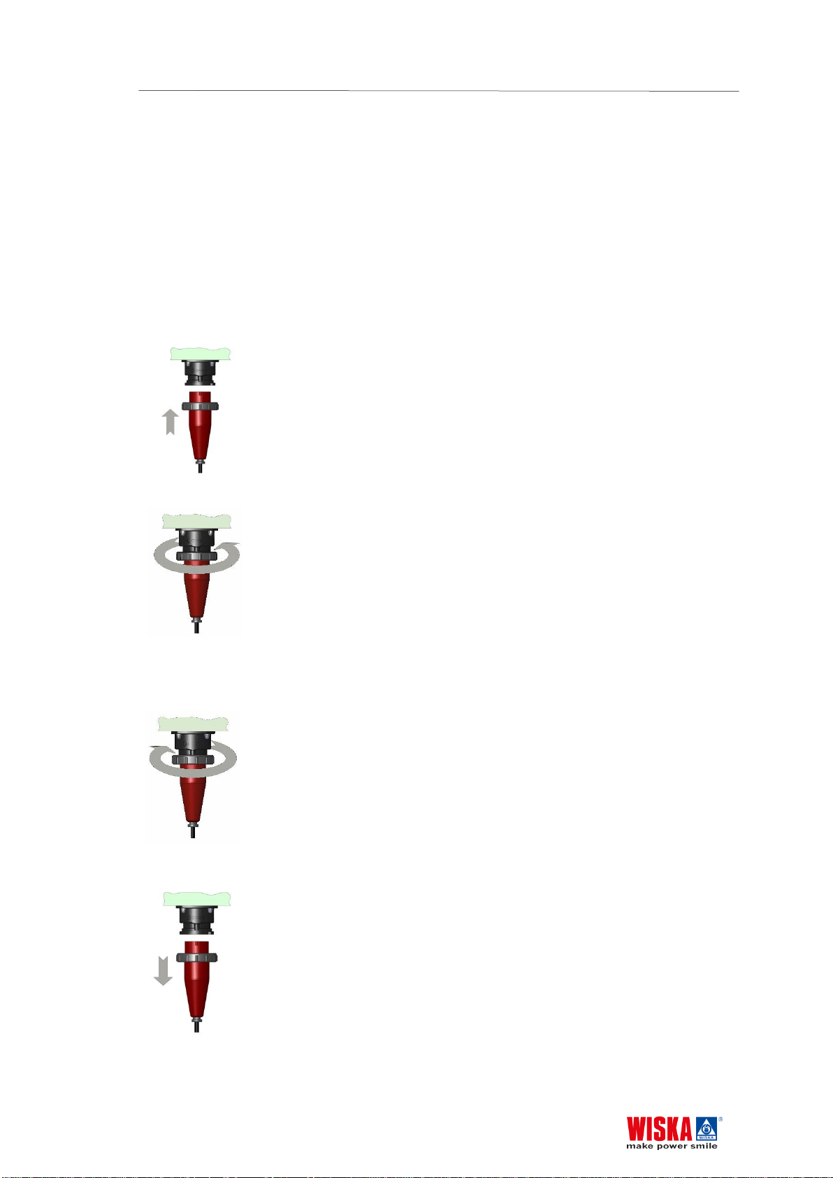
5.3 Replacement of the CEE-socket plug-in unit.........................9
5.4 Replace of the LED-module.................................................12
5.6 Replacement of the MCCB..................................................13
5.7 Replacing the housing seal (seal between housing and
cover) 16
5. ELECTRICAL CIRCUIT DIAGRAMS ........................................ 18
6.1 Circuit diagram without current limiter .................................18
6.2 Circuit diagram with current limiter ...................................... 19
6. GL TYPE APPROVAL ...............................................................20

50103430000_Varitain-PI(Ver1.4)Rev 01122018E.docx About these instructions
3
1. About these instructions
1.1 Symbols and guidance signs in these instructions
Danger! There is a risk to life and limb if the warning is not followed.
Risk of electric shock! There is a risk to life and limb from electricity if the
warning is not followed.
Use disposable gloves! Use disposable gloves for the following work to protect
the material or your health.
Attention! There is a risk to the environment and the device if the warning is not
followed.
Operating steps, that should take place in a certain order, are numbered
sequentially.
Operating steps, that only consist of one step or that don’t have to be followed
in a certain sequence, are marked with a point.
Feedback from executed actions begins with an arrow.
Enumerations begin with an enumeration line.
1.2 Who are these instructions for?
These instructions are intended for the personnel, that are assigned with the assembly,
operation and maintenance of the reefer container sockets.
Risk of electric shock! All electrical installation and repair work may only be
carried out by a qualified electrician!
1, 2, 3, …

System description 50103430000_Varitain-PI(Ver1.4)Rev 01122018E.docx
4
2. System description
The VARITAIN PushIn Socket System is used for the electrical supply of cooling
containers on board seagoing vessels and riverboats, as well as in harbour systems. It is
suitable for 440V±10% 3-phase, but can also be adapted for other voltages in the
factory. The current loading is suitable for cooling containers up to a maximum of 32 A.
Each socket is protected against short circuits and overloads by an in-built circuit-
breaker. The circuit-breaker trips automatically and must be manually returned to the 0-
or 1-Position.
VARITAIN PushIn is an internationally standardized CEE socket device compliant with
IEC 60309-1 (DIN EN 60309-1; VDE 0623-1), IEC 60309-2 (DIN EN 60309-2; VDE
0623-2) and ISO 1496-2.

50103430000_Varitain-PI(Ver1.4)Rev 01122018E.docx System description
5
3.1 The system components
The system consists of system components:
Casing with cable gland(s)
Cover
CEE socket insert (A) with plug contact sleeves (B), circuit-breaker (C), LED
circuit board (D), bayonet cap (E) and mechanical functional elements (F)
Internal wiring
Terminals
Figure 1: Depiction of a CEE socket insert

Description 50103430000_Varitain-PI(Ver1.4)Rev 01122018E.docx
6
3. Description
4.1 Casing
The casing consists of powder coated (color as requested by customer) welded stainless
steel sheet with welded bolts for fixing the components. In order to ensure the degree of
protection IP 67 according to EN 60529, a high quality rubber seal is pressed onto the
upper bent section of the housing.
Fixing lugs on the housing floor are used to fix the equipment.
4.2 CEE socket insert
The CEE socket insert consists of a CEE socket with the contact sleeves (3-phase
sleeves with an earth sleeve), the circuit-breaker (see 1.2.4), the bayonet cap, the
cables and the mechanical actuating elements. Furthermore, the LED unit and, as an
alternative, a pressure compensating element, are installed inside.
The groove for preventing incorrect connection of the CEE socket in respect of the
protective conductor contact defines the voltage and frequency. VARITAIN PushIn is
offered and delivered in its 3-hour setting as standard.
4.3 LED unit
The LED unit is installed in the CEE socket insert and serves as a status signaling
element, indicating that the circuit-breaker has switched. When the LED unit lights up
green, the circuit-breaker is switched on and power is supplied to the CEE socket. The
LED unit does not check whether power is supplied to all three phases.
If the LED unit does not light up, there is no power at the CEE socket.

50103430000_Varitain-PI(Ver1.4)Rev 01122018E.docx Description
7
4.4 Locking system
According to the international regulations the plug can only be plugged in and
withdrawn in the switched off state of the circuit-breaker.
Operation mode:
Power On
Turn the bayonet cap anticlockwise and remove it.
Insert the plug into the socket as far as it will go.
The socket is switched on!
Push the bayonet ring over the socket and tighten it
firmly in a clockwise direction.
Power Off
Release the bayonet ring of the plug by turning it
anticlockwise.
Pull the plug out of the socket.
The socket is switched off!
Tighten the bayonet cap by turning it clockwise.

Description 50103430000_Varitain-PI(Ver1.4)Rev 01122018E.docx
8
Attention:
Please ensure that you only use plugs that conform with international standards
[IEC 60309-1 (DIN EN 60309-1; VDE 0623-1), IEC 60309-2 (DIN EN 60309-2; VDE
0623-2)] are used, as only in this way is the safe operation of the plug device is
ensured. Please particularly ensure that:
- the plug housing is undamaged
- the bayonet ring is present with undamaged seal
- the plug is clean and dry
- the auxiliary protrusion of the plug is present
- the plug is connected in accordance with the valid standards
4.5 Circuit-breaker
Number of poles: 3
Short circuit switch-off capability: Standard 10 kA, 25 kA or 100kA (with current limiter)
Rated insulation voltage:630 VAC
Rated current: max. 32 A
The circuit-breaker is fitted with a trip knob that mechanically simulates tripping, as for
e.g. a short circuit or overload.
4.6 Connection terminals
Two types of connection terminal are fitted in the factory for the power supply,
depending on the type and the number of outputs.
Feed-through terminal for 2.5 mm² to 50 mm², tightening torque 4-5 Nm
Bolt terminal for 6 mm² to 150 mm², clamped cable lugs acc. to DIN 46234,
tightening torque 20Nm

50103430000_Varitain-PI(Ver1.4)Rev 01122018E.docx Repair and maintenance
9
4. Repair and maintenance
5.1 Maintenance
No maintenance is provided in addition to the regular checking of the contact sleeves
(unavoidable wear caused by high numbers of plugging cycles and by dirty or faulty
plugs).
5.2 Repair Attention:
The housing may not be opened when under voltage and only by
trained staff. Safety measure to DIN VDE 0105
Disconnect
Shield unit from restart
Verify disconnected parts are free of voltage
Ground an by-pass
Protect and separate the energised components near by.
Repair / reconditioning work may only be undertaken using WISKA
original spare parts. Changes or alterations to the equipment are not
permitted.
5.3 Replacement of the CEE-socket plug-in unit
Precautionary measures
Switch the entire equipment to the no-voltage state. Remove the cover
and check whether the equipment has been switched to the no-voltage
state with a voltmeter. Ensure that the equipment is not re-activated
while working

Repair and maintenance 50103430000_Varitain-PI(Ver1.4)Rev 01122018E.docx
10
Release the three upper screw terminals of the circuit-breaker and pull the
three cables out of the screw terminals
Release the earth connection

50103430000_Varitain-PI(Ver1.4)Rev 01122018E.docx Repair and maintenance
11
Remove the four cap nuts with a hexagonal spanner of spanner width 10
remove the CEE-socket plug-in unit by pulling it forward

Repair and maintenance 50103430000_Varitain-PI(Ver1.4)Rev 01122018E.docx
12
Installing the socket interior
in the reverse order.
Please make sure that the seal is properly emplaced.
The cap nuts should be tightened with a torque of 3,5 Nm.
The earth connection should be fitted first for safety reasons.
Consider the polarity of the connections when re-fitting The following
torques apply for the terminal points on the circuit-breaker:
1,7 Nm
5.4 Replace of the LED-module
Precautionary measures Switch the entire equipment to the no-voltage
state. Remove the cover and check whether the equipment has been
switched to the no-voltage state with a voltmeter. Ensure that the
equipment is not re-activated while working.
Perform step 1 to step 7 as for the replacement of the CEE socket insert
Disconnect the two cables of the LED unit from the circuit-breaker

50103430000_Varitain-PI(Ver1.4)Rev 01122018E.docx Repair and maintenance
13
Unscrew the two screws of the LED unit
Remove the LED unit from the CEE-socket insert
Installing the LED-module
In the reverse order. The following torques apply for the screws of the LED-
module: 0,5Nm.
Please make sure that the seal is properly emplaced.
The cap nuts should be tightened with a torque of 3,5 Nm.
The earth connection should be fitted first for safety reasons.
Consider the polarity of the connections when re-fitting.
The following torques apply for the terminal points on the circuit-
breaker:
1,7 Nm
5.6Replacement of the MCCB
Precautionary measures
Switch the entire equipment to the no-voltage state. Remove the cover
and check whether the equipment has been switched to the no-voltage
state with a voltmeter. Ensure that the equipment is not re-activated
while working.
Perform step 1 to step 7 as for the replacement of the CEE socket insert
Disconnect the two cables of the LED unit from the circuit-breaker (see
2.2.2)
Loosen the lateral guide of the clamp block, pull the clamp block back and

Repair and maintenance 50103430000_Varitain-PI(Ver1.4)Rev 01122018E.docx
14
remove the insert assembly the insert assembly
Release the three upper screw terminals of the circuit-breaker and remove the
MCCB

50103430000_Varitain-PI(Ver1.4)Rev 01122018E.docx Repair and maintenance
15
Installing the MCCB
in the reverse order
Please make sure that the seal is properly emplaced.
The cap nuts should be tightened with a torque of 4,5 Nm.
The earth connection should be fitted first for safety reasons.
Consider the polarity of the connections when re-fitting.
Achten sie darauf, dass alle Bauteile in ihrer entsprechenden Lage sind.
The following torques apply for the terminal points on the circuit-
breaker:
1,7 Nm

Repair and maintenance 50103430000_Varitain-PI(Ver1.4)Rev 01122018E.docx
16
5.7 Replacing the housing seal (seal between housing and
cover)
Remove the old seal (L).
Cut the seal to size at least 100 mm longer than required.
Apply adhesive WeiconContact VA 2500HT over the entire length to the inner side
of the seal
Firmly press the seal on to the inner edge of the opening aperture of the housing.
Press the seal into the curves of the inner edge.

50103430000_Varitain-PI(Ver1.4)Rev 01122018E.docx Repair and maintenance
17
Cut off the seal leaving an overhang of 3-5 mm.
Apply the adhesive WeiconContact VA 8312 to the profile of the seal.
Press the ends of the seal together and press the seal firmly onto the inner
edge of the housing.
Only careful joining and sticking of the two seal ends guarantees a
functional seal.
Please obtain the article and order numbers of the individual
components from the separate, order-specific spare parts list.

Electrical circuit diagrams 50103430000_Varitain-PI(Ver1.4)Rev 01122018E.docx
18
5. Electrical circuit diagrams
6.1 Circuit diagram without current limiter

50103430000_Varitain-PI(Ver1.4)Rev 01122018E.docx Electrical circuit diagrams
19
6.2 Circuit diagram with current limiter

GL Type Approval 50103430000_Varitain-PI(Ver1.4)Rev 01122018E.docx
20
6. GL Type Approval
Table of contents