WISKA HML - ISO 35 User manual

OPERATING MANUAL
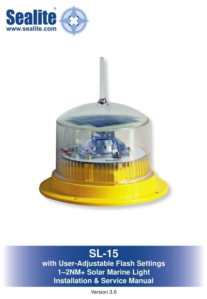
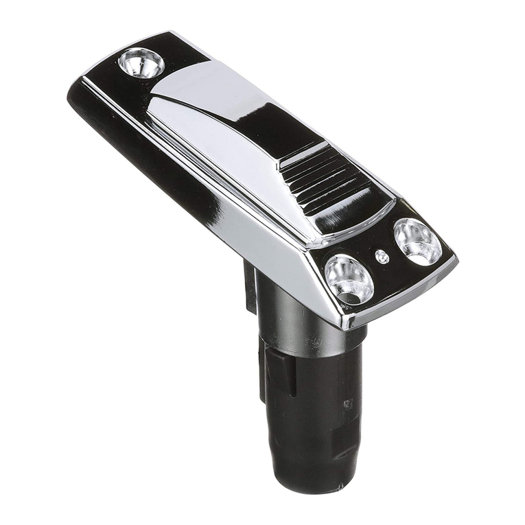
DAY SIGNALLING SEARCHLIGHT
HML - ISO 35

HML-ISO_35_ Rev01122009_E.doc
2

HML-ISO_35_ Rev01122009_E.doc
3
Contents
1. ABOUT THESE INSTRUCTIONS..................................................4
1.1 Symbols and guidance signs in these instructions .........................4
1.2 Who are these instructions for? ......................................................4
2. SAFETY..........................................................................................5
2.1 General information ........................................................................5
2.2 How to handle halogen lamps ........................................................5
2.3 Safety devices.................................................................................6
2.4 Operating conditions .......................................................................6
2.5 Maintenance / Cleaning ..................................................................6
3. AN OVERVIEW OF THE UNIT .......................................................7
3.1 Layout drawing................................................................................7
3.2 Technical Data ................................................................................7
3.3 Dimensions .....................................................................................8
3.4 Circuit diagram................................................................................9
4. COMMISSIONING........................................................................10
4.1 Unpacking .....................................................................................10
4.2 Electrical connections ...................................................................10
5. OPERATION ................................................................................11
6. MAINTENANCE...........................................................................12
6.1 Cleaning ........................................................................................12
6.2 Charging the BatteryPack ISO 35.................................................12
7. REPLACEMENT OF DEFECTIVE PARTS..................................12
7.1 Before starting work ......................................................................12
7.2 Assembly overview .......................................................................12
7.3 Lamp replacement ........................................................................13
8. DISPOSAL ...................................................................................13
9. SPARE PARTS............................................................................14
Contents
HML-ISO_35_ Rev01122009_E.doc
4
1. About these instructions
1.1 Symbols and guidance signs in these instructions
Danger! There is a risk to life and limb if the warning is not followed.
Risk of electric shock! There is a risk to life and limb from electricity if the warning
is not followed.
Attention! There is a risk to the environment and the device if the warning is not
followed.
Use disposable gloves! Use disposable gloves for the following work to protect the
material or your health.
Operating steps, that should take place in a certain order, are numbered
sequentially.
Operating steps, that only consist of one step or that do not have to be followed in a
certain sequence, are marked with a point.
Feedback from executed actions begins with an arrow.
Enumerations begin with an enumeration line.
1.2 Who are these instructions for?
These instructions are intended for the personnel, that are assigned with the assembly or operation
and maintenance of a WISKA searchlight Type HML-ISO 35 or one of its versions.
Risk of electric shock! All electrical installation and repair work may only be carried out by
a qualified electrician!
1, 2, 3, …
About these instructions

HML-ISO_35_ Rev01122009_E.doc
5
2. Safety
The following safety instructions have to be strictly followed! Otherwise you put
yourself and others in danger.
2.1 General information
Intended use
The HML-ISO 35 searchlight is designed for sending light signals. The range
(1 lux at target) of the searchlight is 300 m.
It is developed specially for use on ocean-going vessels and for safety applications
on the coast.
Danger! Unauthorised conversions and changes to the searchlight are not allowed, since
this can endanger persons and may damage the unit. If this is not followed then the unit’s
approval becomes null and void.
Only original spare parts may be used. If this is not followed then the guarantee rights
become null and void.
Risk of getting burned! Never touch the lamp during operation. It can reach 180 °C. Always
allow the searchlight to cool down before maintenance and repair work. In case of burns cool
the injured area immediately and seek medical help.
2.2 How to handle halogen lamps
Transport
●Always store and transport halogen lamps in such a way that the glass bulb
cannot break.
●Leave the lamp in its packing until it will be used.
●Use the packing when transporting the lamp.
●Never touch the lamp with your fingers.
Operation
●Check the lamp before installation for fingerprints and dirt. Remove
fingerprints on the lamp before installation with an alcohol solution and a soft
lint-free cloth.
●Use disposable gloves when handling the lamp. Every fingerprint or other
contamination on the glass bulb of the lamp greatly reduces its lifetime.
●Check the lamp for scratches, cracks or other damage. Do not continue using
damaged lamps.
Lifetime
The average lifetime of the halogen lamp is 2,000 hours.
Disposal
Dispose of the defective halogen lamps properly. Special disposal requirements are not
specified.
Safety

HML-ISO_35_ Rev01122009_E.doc
6
2.3 Safety devices
Radiation / escape of dangerous particles
If the halogen lamp explodes during operation, the casing remains intact and contains any heated
glass splinters.
Overload protection
Electrical means of overload protection, such as fuses have to be provided by the customer. Refer to
chapter 3.2 Technical Specifications regarding the power of the unit.
2.4 Operating conditions
Protection class
The searchlight has protection class IP56 (protected against dust and strong water jets) (as per EN
60529/DIN VDE 0470 Part 1). To obtain this protection class all screwed parts have to be tight.
Electrical lines may only be fed into the units using suitable cable inlets.
2.5 Maintenance / Cleaning
Before carrying out maintenance or cleaning work:
•Pull the mains plug out of the power socket.
•Make sure that the complete electrical system is de-energised.
•Wait until the searchlight has cooled down.
Safety

HML-ISO_35_ Rev01122009_E.doc
7
3. An overview of the unit
3.1 Layout drawing
Base configuration
1 2
3
4
5
6
3.2 Technical Data
Searchlight, HML-ISO 35
Manufacturer WISKA Hoppmann & Mulsow GmbH
Type HML-ISO 35
Illuminant Halogen
Lamp holder GY6,35
Operating voltage (12-24)V DC
Light intensity 90,000 cd
Range 300 m
Diffusion angle 8° I/10
Lamp power 35 W
Average lamp lifetime 2,000 h
Mirror Glass, 150mm
Material Glass fibre reinforced plastic
Colour RAL 9005, black
Diameter 160 mm
Depth 244 mm
Weight 1.8 kg
Protection rating IP 56
Connection cable 5 m
Compass, safe distance 0,5m (Standard-Magnetic-compass)
0,4m (Steering-Magnetic-compass)
BSH – approval no. BSH/4615/4040977/09
1. Glass cover
2. Charger, HML-ISO 35
3. Replacement lamp
4. HML-ISO 35
5. PowerBox, HML-ISO 35
6. Plug 117
An overview of the unit

HML-ISO_35_ Rev01122009_E.doc
8
3.3 Dimensions
Searchlight head
BatteryPack HML-ISO 35
Charger
An overview of the unit

HML-ISO_35_ Rev01122009_E.doc
9
3.4 Circuit diagram
HML-ISO 35 with PowerPack HML-ISO 35
HML-ISO 35 with fixed connection (12V DC-24V DC) on a concentric socket (WISKA Type DK 503)
Cabling HML-ISO 35 internal
Power INPUT
12-24VDC
40 Watt
SIGNAL PUSH-BOTTON
FUNCTION PUSH-BOTTON
BATTERY CONDITION LED
VOTAGE CONVERTER CONTROL BOARD
SAP.NR. 50100464
EMV-POWER BOARD
W09-0051-00
SAP.NR.30100259
HALOGEN LAMP
35 Watt
BLUE
BROWN
OUTPUT
INPUT
An overview of the unit

HML-ISO_35_ Rev01122009_E.doc
10
4. Commissioning
4.1 Unpacking
Check the delivery. Do not start the unit if there is transport damage or missing parts! Contact
WISKA or our sales partner in your country. The address can be found at the back of these
instructions or on the internet under www.wiska.de.
Think about the environment and send the packing for recycling!
4.2 Electrical connections
Risk of electric shock! Electrical connections may only be carried by a qualified electrician.
Please ensure that the mains connection is off and that nobody can accidentally energise the
connections during installation!
The circuit diagram is also included or can be found in chapter 3.4 Circuit diagram.
Electrical connection values (for fixed connections)
Mains voltage: 12V DC- 24V DC at 40 W
Socket: Concentric socket (WISKA Type DK 503)
Required mains fuse: see electrical drawing.
Mains connection
•Observe the relevant national and international regulations!
Before start-up
•Check for correct installation. Wrong connections can cause damage.
•Check for correct connection of the neutral / ground!
•Reinsert the fuse.
Commissioning

HML-ISO_35_ Rev01122009_E.doc
11
5. Operation
1
3 2
Signalling
Pressing the signal button (1) lights the searchlight, so that pressing and releasing of the button
sends light signals.
Torch function
Pressing the signal button (1) and the function button (2) activates the torch mode. When doing so
the lamp lights until one of either buttons is pressed.
SOS function
Pressing the function button (2) sends a permanent SOS signal. This can be stopped by pressing the
signal button (1).
Attention: After starting the SOS function you can’t stop immediately the function by pressing the
function button (2)!
Battery status display
The battery status display (3) lights up if the input voltage is too low. If using the
BatteryPack HML-ISO 35 it should be recharged. (Read Chapter 6.2 Charging the
PowerBox ISO 35)
Operation

HML-ISO_35_ Rev01122009_E.doc
12
6. Maintenance
6.1 Cleaning
Clean the front glass on the outside as needed. Cleaning the inside of the searchlight is not
necessary.
6.2 Charging the BatteryPack ISO 35
Warning! Explosive gases are generated when charging lead batteries. Please ensure
adequate ventilation and avoid fire or naked light.
Connect the BatteryPack ISO 35 with the charger. Open the concentric socket cover on the
BatteryPack ISO 35. Plug the charger into the mains socket. The green “Power“ LED indicates
standby mode. After making contact the unit begins charging the BatteryPack‘s ISO 35
automatically. The red LED indicates the charging process. Once charging is complete the red LED
goes off. The BatteryPack ISO 35 is buffered with a trickle current after charging. If the red LED is off
the BatteryPack ISO 35 is charged, and can be removed from the charger. Disconnect the charger
from the mains after use.
7. Replacement of defective parts
7.1 Before starting work
1. Switch off the unit, e.g. by pulling the concentric plug.
2. Wait until the searchlight has cooled down.
3. Read chapter 2.2 How to handle halogen lamps.
4. Make sure that the halogen lamp does not get damaged during handling.
7.2 Assembly overview
1 1
2
3
Maintenance / Replacement of detective parts

HML-ISO_35_ Rev01122009_E.doc
13
7.3 Lamp replacement
The lamp is defective, if
- it does not light up after switching on,
- the lamp electrodes are burned out,
- the glass bulb is black.
Replace the lamp also if it has reached its average lifetime of 2,000 hours.
Lamp replacement:
1. Disengage the quick releases 1 on the front side and put the front glass carefully to one side.
Note: The halogen lamp 2 plugs in perpendicularly in the lamp holder 3.
2. Pull the defective lamp straight up out of the holder.
3. Place the defective lamp to one side without breaking it.
4. Open the packing of the new lamp.
Attention! Before installing the new lamp check it for fingerprints, scratches or cracks. Don’t
use damaged lamps. Remove any fingerprints or dirt with an alcohol solution and a soft lint-
free cloth.
1. Make sure not to touch the lamp’s glass bulb with your fingers. Use disposable
gloves when handling the lamp to avoid leaving fingerprints.
2. Plug the new lamp into the lamp holder.
3. Reinsert the front glass and close the quick releases.
4. Dispose of the defective halogen lamp properly.
8. Disposal
Electrical components contain substances which are hazardous for the environment. Ensure proper
disposal or send the defect parts to WISKA. The address is on the back page of these instructions.
Replacement of defective parts / Disposal

HML-ISO_35_ Rev01122009_E.doc
14
9. Spare parts
Searchlight head HML-ISO 35
Designation Art. no.
Surrounding frame, HML-ISO 35 30100257
Glass, clear HML-ISO 35 50100361
Mirror unit HML-ISO 35 30100258
Button unit HML-ISO 35 30100253
Quick release rubber HML-ISO 35 30100256
Lamp holder GY6.35 HML-ISO 35 50100367
EMC Electronics HML-ISO 35 30100259
HML light adapter 12-24V 50100464
Halogen lamp 35W, 12VDC; GY6.35 50100370
Concentric plug 117 sw 10016680
Additional parts
Designation Art. no.
Concentric socket DK 503 30070639
PowerPack ISO 35 30100354
Charger, HML-ISO 35 30100356
Front glass, blue HML-ISO 35 50100468
Front glass, green HML-ISO 35 50100467
Front glass, red HML-ISO 35 50100469
All other parts can be obtained by contacting WISKA sales.
Spare parts

HML-ISO_35_ Rev01122009_E.doc
15

WISKA Hoppmann & Mulsow GmbH
Kisdorfer Weg 28
24568 Kaltenkirchen
Germany
+49 (0) 4191/508-100
+49 (0) 4191/508-209
www.wiska.de
Table of contents