Contents
Introduction
Quick Installation------------------------------------------------------------------------------------------------------------------
General Safety description----------------------------------------------------------------------------------------------------
Product description
WX-2ET1FX-S-----------------------------------------------------------------------------------------------------------------------
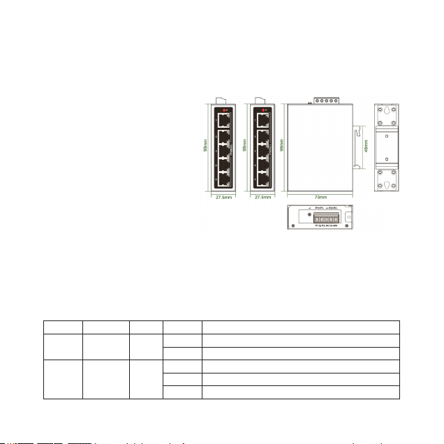
Overview of the device elements---------------------------------------------------------------------------------------
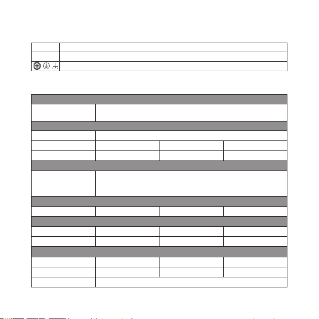
Hardware Specications--------------------------------------------------------------------------------------------------
WX-5ET-S / WX-5GT-S-----------------------------------------------------------------------------------------------------------
Overview of the device elements---------------------------------------------------------------------------------------
Hardware Specications--------------------------------------------------------------------------------------------------
WDH-5ET-DC / WDH-5GT-DC--------------------------------------------------------------------------------------------------
Overview of the device elements---------------------------------------------------------------------------------------
Hardware Specications--------------------------------------------------------------------------------------------------
WDH-5ET-POE / WDH-5GT-POE----------------------------------------------------------------------------------------------
Overview of the device elements---------------------------------------------------------------------------------------
Hardware Specications--------------------------------------------------------------------------------------------------
WDH-8ET-DC / WDH-8GT-DC---------------------------------------------------------------------------------------------------
Overview of the device elements---------------------------------------------------------------------------------------
Hardware Specications-------------------------------------------------------------------------------------------------
WDH-16ET-DC / WDH-16GT-DC-----------------------------------------------------------------------------------------------
Overview of the device elements---------------------------------------------------------------------------------------
Hardware Specications---------------------------------------------------------------------------------------------------
WDH-16ET2GF-DC / WDH-16GT2GF-DC-----------------------------------------------------------------------------------
Overview of the device elements---------------------------------------------------------------------------------------
Hardware Specications--------------------------------------------------------------------------------------------------
Installation
Din rail mounting and twisted pair port datasheet-----------------------------------------------------------------
SFP Installation guide------------------------------------------------------------------------------------------------------
Wiring the terminal block and operating the device-----------------------------------------------------------------
Further support---------------------------------------------------------------------------------------------------------------
1
2
3
4
5
5
6
7
7
8
9
9
10
9
9
10
11
11
12
13
13
14
15
15
16
17
17
17
18
19