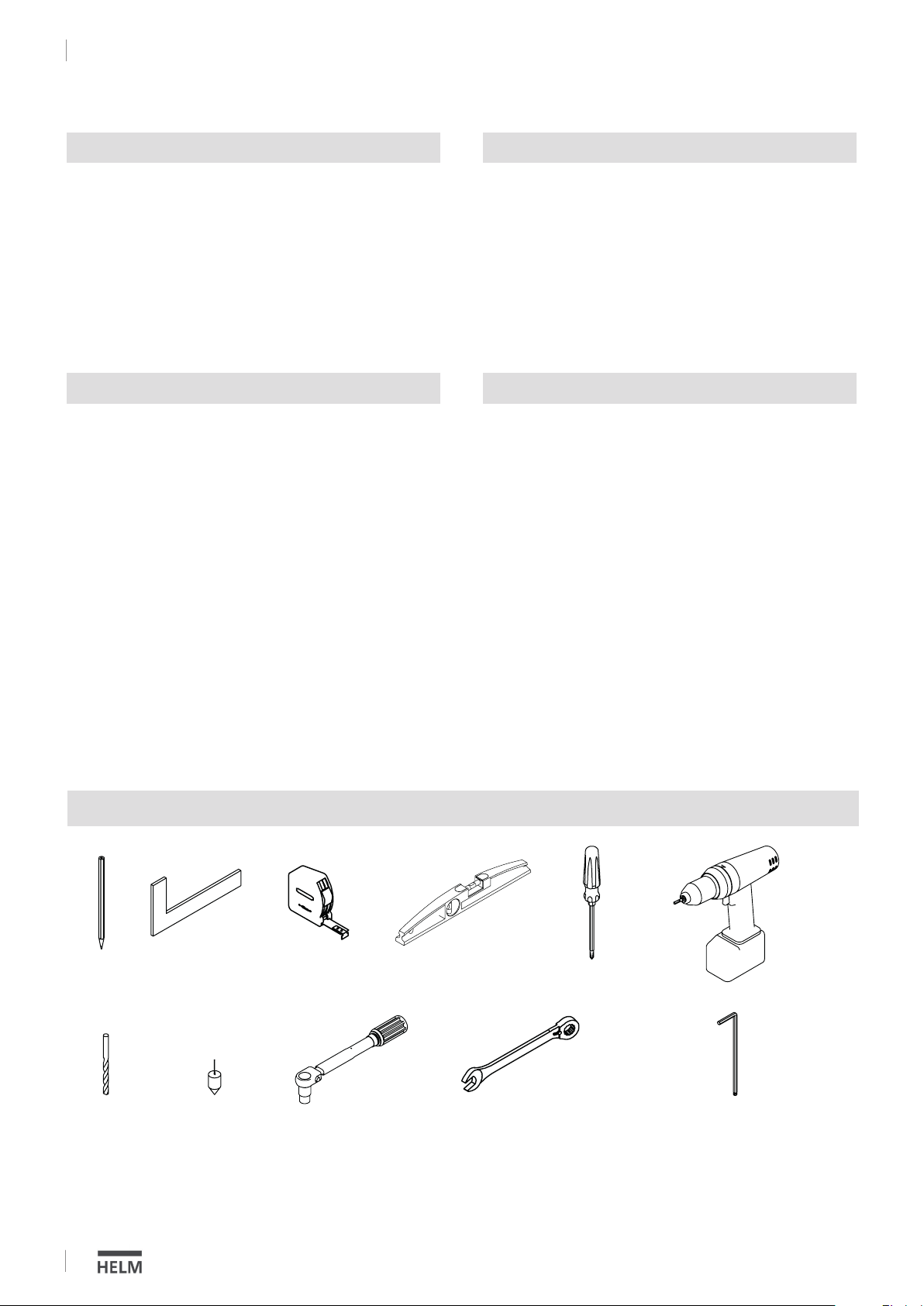
Woelm HELM GT-S-150 User manual

Montageanleitung
Installation instructions
HELM GT-S 150
für Glastüren bis 150 kg
ohne Einzugsdämpfung
einflügelig (mit Berechnungen)
Glasstärken
von 8 und 8,76 mm ESG/VSG
von 10 und 10,76 mm ESG/VSG
von 12 und 12,76 mm ESG/VSG
HELM GT-S 150
for Glass doors up to 150 kg
without damper
single leaf (with calculations)
Glass thickness
from 8 and 8.76 mm TSG/LSG
from 10 and 10.76 mm TSG/LSG
from 12 and 12.76 mm TSG/LSG
MA: DS032011/12.2016

17 Nm
TX30
Größe 2,5 / 3 / 4
Size 2.5 / 3 / 4
SW 13
AF 13
Benötigtes Werkzeug
Required tools
2
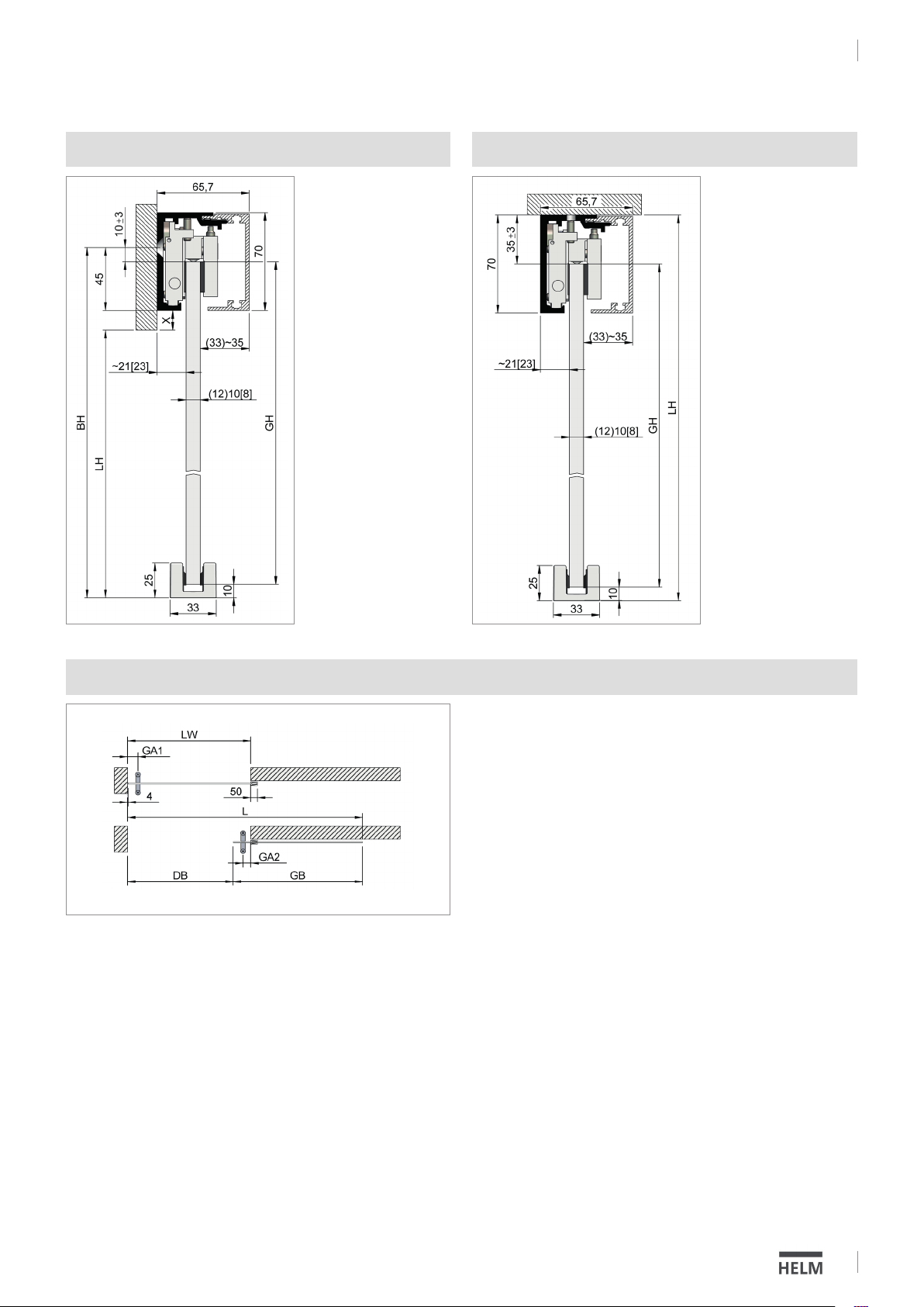
Technische Informationen
• für Einscheibensicherheitsglas (ESG) und Verbund-
sicherheitsglas (VSG aus zweimal ESG oder TVG)
geeignet
• maximales Flügelgewicht 150 kg
• Glasdicken von 8 und 8,76 mm, 10 und 10,76 mm
sowie 12 und 12,76 mm
• mit Festverglasung: Deckenmontage
• ohne Festverglasung: Decken- und Wandmontage
• alle Abmessungen in Millimeter
Wichtige Informationen
Gläser mit selbstreinigender Beschichtung können mit
dem Beschlag HELM GT-S 150 nicht verwendet werden.
Die Glasscheibe muss bei der Montage der Rollapparate
im Bereich der Klemmflächen sauber und fettfrei sein.
Daher die Scheibe in diesem Bereich z.B. mit UV-Spezial-
reiniger oder Aceton reinigen. Weiter empfehlen wir die
Reinigung der Klemmflächen im Rollapparat.
Bei Anlagen die z.B. auf ein Mauerwerk auflaufen, oder
bei zweiflügeligen Anlagen empfehlen wir die Glas-
schiebetüren zusätzlich an den Aufprallseiten mit einem
Glaskantenschutz zu versehen.
Technical information
• Suitable for tempered safety glass (TSG) and laminated
safety glass (LSG consisting of two tempered
or semi-tempered panels)
• Maximum leaf weight 150 kg
• Glass thickness 8 and 8.76 mm, 10 and 10.76 mm,
12 and 12.76 mm
• with fixed glazing: ceiling mounting
• without fixed glazing: ceiling- and wall mounting
• all dimensions in millimetres
Important information
Glass panes with surface protection coating cannot be
used with HELM GT-S 150 clamping technology.
When installing the trolleys the glass pane must be clean
and free of grease in the clamping areas. We
recommend cleaning the pane in this area with alcohol or
acetone cleaner, for example. We also recommend that
you clean the clamping surfaces in the trolleys.
For assemblies that run into a masonry wall, for example
or for double door assemblies, fit the glass sliding doors
with additional glass edge protection on the impact
sides.
DS032011/12.2016
HELM GT-S 150
Allgemeine Informationen

65 135
18
12
Lieferumfang
Included in delivery
Drill template for laminated glass
3
1. Laufschiene (
ohne Seitenteil
)/
Track with fixed glazing
2. Blende/ Cover
3. Abdeckkappen*/ End caps*
Art.-Nr. 0058345 - EV1 eloxiert
Art.-Nr. 0058346 - Edelstahl-Effekt
eloxiert/
Part no. 0058345 - silver anodised
Part no. 0058346 -stainless steel
finish anodised
4. Rollapparat/ Trolley
5. Fangstopper links/
Door catcher, left-hand side
6. Fangstopper rechts
Door catcher, right-hand side
7. Untere Führung/ Bottom guide
8. Unterer Anschlagpuffer* /
Bottom bump stop*
9. Distanzblech / Spacer plate
10. Schraube M5 x 5 / Screw M5 x 5
* nicht im Lieferumfang enthalten/ not included
3
Bohrung für Rollapparat bei VSG
D S 0 3 2 011 /12. 2016
HELM GT-S 150
Allgemeine Informationen (Montage ohne Seitenteil)

Wandmontage ohne Seitenteil
Wall Mount without fixed glazing
Deckenmontage ohne Seitenteil
Ceiling Mount without fixed glazing
Wand-/Deckenmontage ohne Seitenteil bei durchlaufender Wand, mit verdecktem Muschelgriff
Wall/Ceiling Mount without fixed glazing continuous wall with flat-covered door handle
1 Flügel ohne Seitenteil
Panel without fixed glazing
Bsp.:/E.g.:GH = 2157,00; GA1 = 80,00; GD = 10,00;
LW = 950,00; GA2 = 60,00
Glasbreite Schiebetür (GB):
Door panel width (GB):
GB = LW + 50,00 + 30,00
Bsp.: /E.g.:GB = 950,00 + 50,00 + 30,00 = 1030,00
Gewicht Schiebetür (G) = kg:
Door panel weight (G) = kg:
G = GH x GB x GD x 0,0000025
Bsp.:/E.g.: G = 2157,00 x 1030,00 x 10,00 x 0,0000025 = 55,54
Laufschienenlänge (L) MG verdeckt:
Track length (L) door handle (covered):
L = GB + LW + 30,00
Bsp.:/E.g.: L = 1030,00 + 950,00 + 30,00 = 2010,00
Durchgangsbreite (DB) MG verdeckt:
Walk-through distance (DB) covered handle:
DB = LW
Bsp.:/E.g.: DB = 950,00
Legende:
LH = lichte Höhe
LW = lichte Weite
BH = Bohrhöhe
GH = Glashöhe
GB = Glasbreite Schiebetür
MG = Muschelgriff
L = Laufschienenlänge
GA1 = Griffabstand 1
GA2 = Griffabstand 2
GD = Glasdicke
DB = Durchgangsbreite
G = Gewicht in kg
T = Abdeckprofillänge
S = Seitenteil
BP = Bodenprofil
GHS = Glashöhe Seitenteil
Key:
LH = Clear height
LW = Clear width
BH = Drill height
GH = Glass height
GB = Door panel width
MG = Door handle
L = Track length
GA1 = Handle distance 1
GA2 = Handle distance 2
GD = Glass thickness
DB = Walk through distance
G = Weight
T = Cover profile length
S = Side panel
BP = Floor profile
GHS = Side panel height
4
Bohrhöhe (BH):
Drilling hight (BH):
BH = LH + X + 45
Glashöhe (GH):
Glass hight (GH):
GH = BH – 10 – 10
Glashöhe (GH):
Glass hight (GH):
GH = LH – 10 – 35
DS032011/12.2016
HELM GT-S 150
Montage ohne Seitenteil / Installation without fixed glazing

Wandmontage ohne Seitenteil
Wall Mount without fixed glazing
Deckenmontage ohne Seitenteil
Ceiling Mount without fixed glazing
Wand-/Deckenmontage ohne Seitenteil bei durchlaufender Wand, mit halb verdecktem Muschelgriff
Wall/Ceiling Mount without continuous wall, half covered door handle
1 Flügel ohne Seitenteil
Panel without fixed glazing
Bsp.:/E.g.:GH = 2157,00; GA1 = 80,00; GD = 10,00;
LW = 950,00; GA2 = 60,00
Glasbreite Schiebetür (GB):
Door panel width (GB):
GB = LW + 50,00 + 30,00
Bsp.: /E.g.:GB = 950,00 + 50,00 + 30,00 = 1030,00
Gewicht Schiebetür (G) = kg:
Door panel weight (G) = kg:
G = GH x GB x GD x 0,0000025
Bsp.:/E.g.: G = 2157,00 x 1030,00 x 10,00 x 0,0000025 = 55,54
Laufschienenlänge (L) MG verdeckt:
Track length (L) door handle (covered):
L = GB + LW - GA1
Bsp.:/E.g.: L = 1030,00 + 950,00 - 80,00 = 1900,00
Durchgangsbreite (DB) MG halb verdeckt:
Walk-through distance (DB) half covered handle:
DB = LW - GA1 - 30,00
Bsp.:/E.g.: DB = 950,00 - 80,00 - 30,00 = 840,00
Legende:
LH = lichte Höhe
LW = lichte Weite
BH = Bohrhöhe
GH = Glashöhe
GB = Glasbreite Schiebetür
MG = Muschelgriff
L = Laufschienenlänge
GA1 = Griffabstand 1
GA2 = Griffabstand 2
GD = Glasdicke
DB = Durchgangsbreite
G = Gewicht in kg
T = Abdeckprofillänge
S = Seitenteil
BP = Bodenprofil
GHS = Glashöhe Seitenteil
Key:
LH = Clear height
LW = Clear width
BH = Drill height
GH = Glass height
GB = Door panel width
MG = Door handle
L = Track length
GA1 = Handle distance 1
GA2 = Handle distance 2
GD = Glass thickness
DB = Walk through distance
G = Weight
T = Cover profile length
S = Side panel
BP = Floor profile
GHS = Side panel height
5
Bohrhöhe (BH):
Drilling hight (BH):
BH = LH + X + 45
Glashöhe (GH):
Glass hight (GH):
GH = BH – 10 – 10
Glashöhe (GH):
Glass hight (GH):
GH = LH – 10 – 35
D S 0 3 2 011 /12. 2016
HELM GT-S 150
Montage ohne Seitenteil / Installation without fixed glazing

Wand-/Deckenmontage ohne Seitenteil bei durchlaufender Wand, mit Stangengriff
Wall/Ceiling mount without fixed glazing w/continuous wall with ladder handle
Wandmontage ohne Seitenteil
Wall Mount without fixed glazing
Deckenmontage ohne Seitenteil
Ceiling Mount without fixed glazing
1 Flügel ohne Seitenteil
Panel without fixed glazing
Bsp.:/E.g.:GH = 2157,00; GA1 = 80,00; GD = 10,00;
LW = 950,00; GA2 = 60,00
Glasbreite Schiebetür (GB):
Door panel width (GB):
GB = LW + 50,00 + 30,00
Bsp.:/E.g.: GB = 950,00 + 50,00 + 30,00 = 1030,00
Gewicht Schiebetür (G) = kg:
Door panel weight (G) = kg:
G = GH x GB x GD x 0,0000025
Bsp.: /E.g.:G = 2157,00 x 1030,00 x 10,00 x 0,0000025 = 55,54
Laufschienenlänge (L):
Track length (L):
L = GB + LW - GA1 - GA2
Bsp.:/E.g.: L = 1030,00 + 950,00 - 80,00 - 60,00 = 1840,00
Durchgangsbreite (DB):
Walk-through distance (DB):
DB = LW - GA1 - GA2 - 30,00
Bsp.:/E.g.: DB = 950,00 - 80,00 - 60,00 - 30,00 = 780,00
Legende:
LH = lichte Höhe
LW = lichte Weite
BH = Bohrhöhe
GH = Glashöhe
GB = Glasbreite Schiebetür
MG = Muschelgriff
L = Laufschienenlänge
GA1 = Griffabstand 1
GA2 = Griffabstand 2
GD = Glasdicke
DB = Durchgangsbreite
G = Gewicht in kg
T = Abdeckprofillänge
S = Seitenteil
BP = Bodenprofil
GHS = Glashöhe Seitenteil
Key:
LH = Clear height
LW = Clear width
BH = Drill height
GH = Glass height
GB = Door panel width
MG = Door handle
L = Track length
GA1 = Handle distance 1
GA2 = Handle distance 2
GD = Glass thickness
DB = Walk through distance
G = Weight
T = Cover profile length
S = Side panel
BP = Floor profile
GHS = Side panel height
6
Bohrhöhe (BH):
Drilling hight (BH):
BH = LH + X + 45
Glashöhe (GH):
Glass hight (GH):
GH = BH – 10 – 10
Glashöhe (GH):
Glass hight (GH):
GH = LH – 10 – 35
DS032011/12.2016
HELM GT-S 150
Montage ohne Seitenteil / Installation without fixed glazing

Wand-/Deckenmontage ohne Seitenteil bei nicht durchlaufender Wand, mit verdecktem Muschelgriff
Wall/Ceiling mount without fixed panel with end wall, covered flat handle
Wandmontage ohne Seitenteil
Wall Mount without fixed glazing
Deckenmontage ohne Seitenteil
Ceiling Mount without fixed glazing
1 Flügel ohne Seitenteil
Panel without fixed glazing
Bsp.:/E.g.:GH = 2157,00; GA1 = 80,00; GD = 10,00;
LW = 950,00; GA2 = 60,00
Glasbreite Schiebetür (GB):
Door panel width (GB):
GB = LW + 50,00 - 4,00
Bsp.:/E.g.: GB = 950,00 + 50,00 - 4,00 = 996,00
Gewicht Schiebetür (G) = kg:
Door panel weight (G) = kg:
G = GH x GB x GD x 0,000002
G = GH x GB x GD x 0,0000025
Bsp.:/E.g.: G = 2157,00 x 996,00 x 10,00 x 0,0000025 = 53,71
Laufschienenlänge (L) MG verdeckt:
Track length (L) MG covered:
L = GB + LW
Bsp.:/E.g.: L = 996,00 + 950,00 = 1946,00
Durchgangsbreite (DB) MG verdeckt:
Walk-through distance (DB) covered:
DB = LW
Bsp.:/E.g.: DB = 950,00
Legende:
LH = lichte Höhe
LW = lichte Weite
BH = Bohrhöhe
GH = Glashöhe
GB = Glasbreite Schiebetür
MG = Muschelgriff
L = Laufschienenlänge
GA1 = Griffabstand 1
GA2 = Griffabstand 2
GD = Glasdicke
DB = Durchgangsbreite
G = Gewicht in kg
T = Abdeckprofillänge
S = Seitenteil
BP = Bodenprofil
GHS = Glashöhe Seitenteil
Key:
LH = Clear height
LW = Clear width
BH = Drill height
GH = Glass height
GB = Door panel width
MG = Door handle
L = Track length
GA1 = Handle distance 1
GA2 = Handle distance 2
GD = Glass thickness
DB = Walk through distance
G = Weight
T = Cover profile length
S = Side panel
BP = Floor profile
GHS = Side panel height
7
Bohrhöhe (BH):
Drilling hight (BH):
BH = LH + X + 45
Glashöhe (GH):
Glass hight (GH):
GH = BH – 10 – 10
Glashöhe (GH):
Glass hight (GH):
GH = LH – 10 – 35
D S 0 3 2 011 /12. 2016
HELM GT-S 150
Montage ohne Seitenteil / Installation without fixed glazing

Wandmontage ohne Seitenteil
Wall Mount without fixed glazing
Deckenmontage ohne Seitenteil
Ceiling Mount without fixed glazing
Wand-/Deckenmontage ohne Seitenteil bei nicht durchlaufender Wand, mit halb verdecktem Muschelgriff
Wall/Ceiling mount without fixed panel with end wall, half covered flat handle
1 Flügel ohne Seitenteil
Panel without fixed glazing
Bsp.:/E.g.:GH = 2157,00; GA1 = 80,00; GD = 10,00;
LW = 950,00; GA2 = 60,00
Glasbreite Schiebetür (GB):
Door panel width (GB):
GB = LW + 50,00 - 4,00
Bsp.:/E.g.: GB = 950,00 + 50,00 - 4,00 = 996,00
Gewicht Schiebetür (G) = kg:
Door panel weight (G) = kg:
G = GH x GB x GD x 0,0000025
Bsp.:/E.g.: G = 2157,00 x 996,00 x 10,00 x 0,0000025 = 53,71
Laufschienenlänge (L) MG halb verdeckt:
Track length (L) MG half covered:
L = GB + LW - GA1 + 4,00
Bsp.:/E.g.: L = 996,00 + 950,00 - 80,00 + 4,00 = 1870,00
Durchgangsbreite (DB) MG halb verdeckt:
Walk-through distance (DB) half covered:
DB = LW - GA1 + 4,00
Bsp.:/E.g.: DB = 950,00 - 80,00 + 4,00 = 874,00
Legende:
LH = lichte Höhe
LW = lichte Weite
BH = Bohrhöhe
GH = Glashöhe
GB = Glasbreite Schiebetür
MG = Muschelgriff
L = Laufschienenlänge
GA1 = Griffabstand 1
GA2 = Griffabstand 2
GD = Glasdicke
DB = Durchgangsbreite
G = Gewicht in kg
T = Abdeckprofillänge
S = Seitenteil
BP = Bodenprofil
GHS = Glashöhe Seitenteil
Key:
LH = Clear height
LW = Clear width
BH = Drill height
GH = Glass height
GB = Door panel width
MG = Door handle
L = Track length
GA1 = Handle distance 1
GA2 = Handle distance 2
GD = Glass thickness
DB = Walk through distance
G = Weight
T = Cover profile length
S = Side panel
BP = Floor profile
GHS = Side panel height
8
Bohrhöhe (BH):
Drilling hight (BH):
BH = LH + X + 45
Glashöhe (GH):
Glass hight (GH):
GH = BH – 10 – 10
Glashöhe (GH):
Glass hight (GH):
GH = LH – 10 – 35
DS032011/12.2016
HELM GT-S 150
Montage ohne Seitenteil / Installation without fixed glazing

Wandmontage ohne Seitenteil
Wall Mount without fixed glazing
Deckenmontage ohne Seitenteil
Ceiling Mount without fixed glazing
Wand-/Deckenmontage ohne Seitenteil bei nicht durchlaufender Wand, mit Stangengriff
Wall/Ceiling mount without fixed glazing without continuous wall with ladder handle
1 Flügel ohne Seitenteil
Panel without fixed glazing
Bsp.:/E.g.:GH = 2157,00; GA1 = 80,00; GD = 10,00;
LW = 950,00; GA2 = 60,00
Glasbreite Schiebetür (GB):
Door panel width (GB):
GB = LW + 50,00 - 4,00
Bsp.:/E.g.: GB = 950,00 + 50,00 - 4,00 = 996,00
Gewicht Schiebetür (G) = kg:
Door panel weight (G) = kg:
G = GH x GB x GD x 0,0000025
Bsp.:/E.g.: G = 2157,00 x 996,00 x 10,00 x 0,0000025 = 53,71
Laufschienenlänge (L):
Track length (L):
L = GB + LW - GA1 - GA2 + 4,00
Bsp.:/E.g.: L = 996,00 + 950,00 - 80,00 - 60,00 + 4,00 = 1810,00
Durchgangsbreite (DB):
Walk-through distance (DB):
DB = LW - GA1 - GA2 + 4,00
Bsp.:/E.g.: DB = 950,00 - 80,00 - 60,00 + 4,00 = 814,00
Legende:
LH = lichte Höhe
LW = lichte Weite
BH = Bohrhöhe
GH = Glashöhe
GB = Glasbreite Schiebetür
MG = Muschelgriff
L = Laufschienenlänge
GA1 = Griffabstand 1
GA2 = Griffabstand 2
GD = Glasdicke
DB = Durchgangsbreite
G = Gewicht in kg
T = Abdeckprofillänge
S = Seitenteil
BP = Bodenprofil
GHS = Glashöhe Seitenteil
Key:
LH = Clear height
LW = Clear width
BH = Drill height
GH = Glass height
GB = Door panel width
MG = Door handle
L = Track length
GA1 = Handle distance 1
GA2 = Handle distance 2
GD = Glass thickness
DB = Walk through distance
G = Weight
T = Cover profile length
S = Side panel
BP = Floor profile
GHS = Side panel height
9
Bohrhöhe (BH):
Drilling hight (BH):
BH = LH + X + 45
Glashöhe (GH):
Glass hight (GH):
GH = BH – 10 – 10
Glashöhe (GH):
Glass hight (GH):
GH = LH – 10 – 35
D S 0 3 2 011 /12. 2016
HELM GT-S 150
Montage ohne Seitenteil / Installation without fixed glazing

Montage ohne Seitenteil
Installation without fixed glazing
Größe 2,5
Size 2.5
1
2Die Laufschiene waagerecht und lotrecht an die Wand bzw. Decke montieren.
Wichtig: Nur Befestigungsmaterial verwenden, das für den vorhandenen Untergrund geeignet ist.
Install the track level either onto wall or ceiling.
NOTE: Only use fixing material which is suitable for the existing substrate.
10
Die Fangstopper stirnseitig in die Laufschiene einschieben und am jeweiligen Schienenende grob positionieren, ohne eine
Befestigungsbohrung zu verdecken.
Slide the door catchers into the track and position in desired location without covering any fixing bore holes.
DS032011/12.2016
HELM GT-S 150
Montage ohne Seitenteil / Installation without fixed glazing

4
3
Montage ohne Seitenteil
Installation without fixed glazing
11
Mit einem Lot die Position der unteren Führung ermit-
teln. Bohrbild übertragen, bohren und die untere Füh-
rung befestigen.
Use a plumb line to determine the position of the
bottom guide. Transfer the drilling pattern, drill and fix
the bottom guide.
Die Rollapparate sind werkseitig für eine Verbundsicherheitsglasscheibe (VSG) vormontiert. Bei der Verwendung einer
Einscheibensicherheitsglasscheibe (ESG) müssen die Bolzen inkl. Hülse (4a) entfernt werden. Bei den Klemmplatten der
Rollapparate müssen entsprechend der Glasstärke die Klemmeinlagen eingeklebt werden.
The trolleys are pre-assembled for a laminated safety glass panel. If using a tempered glass, the bolts including the sleeves (4a)
must be removed.The clamping inserts must be stuck onto the clamping jaws according to the glass thickness. Please peel off
the sticker to use self adhesive surface.
D S 0 3 2 011 /12. 2016
HELM GT-S 150
Montage ohne Seitenteil / Installation without fixed glazing

TX30
17 Nm
6
Größe 3
Size 3
5
Montage ohne Seitenteil
Installation without fixed glazing
12
Die Glasscheibe muss bei der Montage der Rollapparate im Bereich der Klemmflächen sauber und fettfrei sein. Daher die Schei-
be in diesem Bereich z.B. mit UV-Spezialreiniger oder Aceton reinigen. Weiter empfehlen wir die Reinigung der Klemmflächen
im Rollapparat. Die Rollapparate ganz auf die Glasscheibe aufschieben, bis die Schutzgummis kopfseitig an der Scheibe anlie-
gen. Die Rollapparate jeweils 45 mm von den Stirnseiten positionieren. Die Rollapparate mit einem Anzugsmoment von 17 Nm
auf die Glasscheibe klemmen, hierfür einen Drehmomentschlüssel mit Torx-Aufsatz (TX30) verwenden.
When installing the trolleys the glass pane must be clean and free of grease in the clamping areas. We recommend cleaning
the pane in this area with alcohol or acetone cleaner, for example. We also recommend that you clean the clamping surfaces
in the trolleys. Push the trolleys onto the glass panel until the protective rubber pushes against the top of the panel. Position
each of the trolleys 45 mm from the edge of the glass. Tighten clamp with a torque of 17 Nm and use a torque wrench with
Torx bit (TX30).
Die Sicherungsschrauben (1) an den Rollapparaten soweit herunter drehen, bis diese bündig mit der Klemmplatte sind.
Lower the safety screws (1) on the trolleys until they are flush with clamping plate.
DS032011/12.2016
HELM GT-S 150
Montage ohne Seitenteil / Installation without fixed glazing

Montage ohne Seitenteil
Installation without fixed glazing
SW 13
AF 13
Größe 2,5 / 3 / 4
Size 2.5 / 3 / 4
7
13
Wichtig: Die Laufflächen der Schiene und die Rol-
len vor dem Einsetzen des Türblattes säubern.
Die Rollapparate sind mit wartungsfreien Kugella-
gern ausgestattet und dürfen nicht nachgefettet
werden.
Das Türblatt in die Laufschiene hängen und über die
Exzenterschrauben (2) mit Hilfe einer Wasserwaage aus-
richten (+/-3mm). Anschließend die Exzenterschrauben
(2)über die Kontermuttern fixieren.
Die Sicherungsschrauben (1) soweit hoch drehen, bis ein
leichter Kontakt zur Laufschiene besteht, dann diese
wieder um eine ½ Umdrehung zurück drehen.
Wichtig: Die Sicherungsschrauben verhindern das
Ausheben der Tür bei unsachgemäßer Betätigung.
Die Endanschläge in der Laufschiene am jeweiligen
Schienenende so positionieren, dass die gewünschte
Türöffnung freigegeben wird und wie folgt klemmen:
zuerst die obere Schraube (5a) des Fangstoppers anzie-
hen, bis sich das Bauteil in der Schiene gesetzt hat. Nun
die unteren Schrauben (5b) leicht anziehen. Anschlie-
ßend beide Schrauben eine ¼ Umdrehung nachziehen.
IMPORTANT: Clean running track before inserting
door. All trolleys are equipped with maintenance-
free bearings and should not be greased.
Position the door panel in the track and align using the
eccentric screws (2) and a level (+/-3mm). Then tighten
the eccentric screws (2) using the counter nuts. Turn the
locking screws (1) until they are in light contact with the
track, then turn them back again by a ½ turn.
Important: The locking screws serve as the anti-
jump system and prevent the door from jumping
out if improperly used.
Position the trolley stops in the track at the respective
end of the track so that the required door opening is
achieved and clamp as follows: screw the top screw (5a)
on the door catcher, until the component has set in the
track. Now tighten the bottom screw (5b) slightly. Then
retighten both screws by turning them an additional ¼
turn.
D S 0 3 2 011 /12. 2016
HELM GT-S 150
Montage ohne Seitenteil / Installation without fixed glazing

Größe 2,5
Size 2.5
Größe 2,5
Size 2.5
Montage ohne Seitenteil
Installation without fixed glazing
8
Die Blende in die Laufschiene einhängen, positionieren,
andrücken und die Klemmschrauben mit einem Innen-
sechskantschlüssel anziehen. Damit im Durchgangsbe-
reich beginnen. Der Innensechskantschlüssel kann von
Schraube zu Schraube in der Führungsrille entlang ge-
führt werden.
Wichtig: Bei Demontage der Blende die Klemm-
schrauben komplett herausdrehen.
Clip the cover into the track, position it and apply
pressure onto the cover to snap in place. Use the Allen
key to tighten the clamping screws. Start in the
walkthrough area. The Allen key can be guided from
screw to screw in the guide groove.
Important: In case of dismantling the cover,
completely remove the clamping screws.
9
Die Klemmschrauben (M5x5) für die Blende in die Lauf-
schiene eindrehen. Die Einschraubtiefe mit dem Dis-
tanzblech bestimmen, d.h. die Schrauben so weit ein-
drehen, bis ein leichter Kontakt zum Distanzblech
entsteht.
Es sind dabei nur die Gewindebohrungen zu verwen-
den, die beim Verschieben der Tür von unten frei zu-
gänglich sind.
Screw the clamping screws (M5x5) for the cover into the
track. Use the spacer plate to determine the depth.
Tighten the screws until they lightly touch the spacer
plate. Only use the threaded holes, which are accessible
from the bottom when the door is moved.
10
14
Bei Verwendung der optionalen Abdeckkappen:
Die Stirnseiten der Profile mit z.B. Spiritus oder Aceton
reinigen, anschließend die optionalen Abdeckkappen
seitlich auf die Blende kleben.
In case of using the optional end caps:
Clean both end surfaces of the tracks with alcohol or
acetone cleaner before attaching end caps.
DS032011/12.2016
HELM GT-S 150
Montage ohne Seitenteil / Installation without fixed glazing

15
D S 0 3 2 011 /12. 2016
HELM GT-S 150
Notizen / Notes

65 135
18
12
Lieferumfang
Included in delivery
Bohrung für Laufwagen bei VSG
Drill template for laminated glass
16
1. Laufschiene (
mit Seitenteil
)/
Track with fixed glazing
2. Blende/ Cover
3. Abdeckkappen*/ End caps*
Art.-Nr. 0058315 - EV1 eloxiert
Art.-Nr. 0058316 - Edelstahl-Effekt
eloxiert/
Part no. 0058315 - silver anodised
Part no. 0058316 - stainless steel
finish anodised
4. Rollapparat/ Trolley
5. Fangstopper links/
Door catcher, left-hand side
6. Fangstopper rechts
Door catcher, right-hand side
7. Untere Führung/ Bottom guide
8. Distanzblech/ Spacer plate
9. Schraube M5 x 5/ Screw M5 x 5
10. U-Schiene mit Seitenteil/
U-channel for side panel
11. Abdeckprofil/ Cover profile
*nicht im Lieferumfang enthalten/
*not included
DS032011/12.2016
HELM GT-S 150
Montage mit Seitenteil / Installation with fixed glazing

Deckenmontage mit Seitenteil bei durchlaufender Wand, mit verdecktem Muschelgriff
Ceiling mount with fixed glazing - continuous wall with covered flat handle
Legende:
LH = lichte Höhe
LW = lichte Weite
BH = Bohrhöhe
GH = Glashöhe
GB = Glasbreite Schiebetür
MG = Muschelgriff
L = Laufschienenlänge
GA1 = Griffabstand 1
GA2 = Griffabstand 2
GD = Glasdicke
DB = Durchgangsbreite
G = Gewicht in kg
T = Abdeckprofillänge
S = Seitenteil
BP = Bodenprofil
GHS = Glashöhe Seitenteil
1 Flügel mit Seitenteil
Panel with fixed glazing
Bsp.:/E.g.: GH = 2157,00; GA1 = 80,00; GD = 10,00;
LW = 1800,00; GA2 = 60,00
Laufschienenlänge (L)
Track length (L)
L = LW + 60,00
Bsp.:/E.g.: L = 1800,00 + 60,00 = 1860,00
Länge Abdeckprofil (L)
Cover profile length (L)
T = L - S
Bsp.:/E.g.: T = 1860,00 - 955,00 = 905,00
Mit Muschelgriff
Glasbreite Schiebetür (GB) max. DB MG verdeckt
With flat handle
Door panel width (GB)
max. DB, door handle (covered)
LW + 60,00 + 50,00
2,00
1800,00 + 60,00 + 50,00
2,00
Gewicht Schiebetür (G) in kg MG verdeckt
Door panel
weight
(G) in kg door handle (covered)
G = GH x GB x GD x 0,0000025
Bsp.:/E.g.: G = 2157,00 x 955,00 x 10,00 x 0,0000025 = 51,5
Glasbreite Seitenteil (S) max. DB, MG verdeckt
Glass width with fixed glazing (S) max. DB, door handle (covered)
LW + 60,00 + 50,00
2,00
1800,00 + 60,00 + 50,00
2,00 = 955,00
Länge Bodenprofil (BP) MG verdeckt
U-channel length (BP) door handle (covered)
BP = S
Bsp.:/E.g.: BP = 955,00
Durchgangsbreite (DB) MG verdeckt
Walk-through distance (DB) door handle (covered)
DB = L - S - 30,00
Bsp.:/E.g.: DB = 1860,00 - 955,00 - 30,00 = 875,00
Bsp.:/E.g.: GB =
GB =
= 955,00
Bsp.:/E.g.: S =
S =
Key:
LH = Clear height
LW = Clear width
BH = Drill height
GH = Glass height
GB = Door panel width
MG = Door handle
L = Track length
GA1 = Handle distance 1
GA2 = Handle distance 2
GD = Glass thickness
DB = Walk through distance
G = Weight
T = Cover profile length
S = Side panel
BP = Floor profile
GHS = Side panel height
17
Glashöhe (GH):
Glass hight (GH):
GH = LH – 10 – 35
GHS = LH – 43
D S 0 3 2 011 /12. 2016
HELM GT-S 150
Montage mit Seitenteil / Installation with fixed glazing

Deckenmontage mit Seitenteil bei durchlaufender Wand, mit Stangengriff
Ceiling mount with fixed glazing continuous wall, ladder handle
Key:
LH = Clear height
LW = Clear width
BH = Drill height
GH = Glass height
GB = Door panel width
MG = Door handle
L = Track length
GA1 = Handle distance 1
GA2 = Handle distance 2
GD = Glass thickness
DB = Walk through distance
G = Weight
T = Cover profile length
S = Side panel
BP = Floor profile
GHS = Side panel height
Legende:
LH = lichte Höhe
LW = lichte Weite
BH = Bohrhöhe
GH = Glashöhe
GB = Glasbreite Schiebetür
MG = Muschelgriff
L = Laufschienenlänge
GA1 = Griffabstand 1
GA2 = Griffabstand 2
GD = Glasdicke
DB = Durchgangsbreite
G = Gewicht in kg
T = Abdeckprofillänge
S = Seitenteil
BP = Bodenprofil
GHS = Glashöhe Seitenteil
1 Flügel mit Seitenteil
Panel with fixed glazing
Bsp.:/E.g.: GH = 2157,00; GA1 = 80,00; GD = 10,00;
LW = 1800,00; GA2 = 60,00
Laufschienenlänge (L)
Track length (L)
L = LW + 60,00
Bsp.:/E.g.: L = 1800,00 + 60,00 = 1860,00
Länge Abdeckprofil (L)
Cover profile length (L)
T = L - S
Bsp.:/E.g.: T = 1860,00 - 870,00 = 990,00
Glasbreite Schiebetür (GB) max. DB
Door panel width (GB)
max. DB:
LW + 90,00 + GA1 + GA2 - 50,00
2,00
1800,00 + 90,00 + 80,00 + 60,00 + 50,00
2,00
Gewicht Schiebetür (G) in kg
Door panel
weight
(G) in kg
G = GH x GB x GD x 0,0000025
Bsp.:/E.g.: G = 2157,00 x 1040,00 x 10,00 x 0,0000025 = 56,08
Glasbreite Seitenteil (S) max. DB
Glass width with fixed glazing (S) max. DB:
LW + 30,00 - GA1 - GA2 + 50,00
2,00
1800,00 + 30,00 - 80,00 - 60,00 + 50,00
2,00 = 870,00
Länge Bodenprofil (BP):
U-channel length (BP)
BP = S
Bsp.:/E.g.: BP = 870,00
Durchgangsbreite (DB)
Walk-through distance (DB)
LW
2
1800,00
2
DB =
Bsp.:/E.g.: DB =
- GA1 - GA2 + 30,00
- 80,00 - 60,00 + 30,00 = 790,00
Bsp.:/E.g.: S =
S =
GB =
Bsp.:/E.g.: GB = = 1040
18
Glashöhe (GH):
Glass hight (GH):
GH = LH – 10 – 35
GHS = LH – 43
DS032011/12.2016
HELM GT-S 150
Montage mit Seitenteil / Installation with fixed glazing

Deckenmontage mit Seitenteil bei nicht durchlaufender Wand, mit verdecktem Muschelgriff
Ceiling wall with fixed panel, fixed wall, covered flat handle
Key:
LH = Clear height
LW = Clear width
BH = Drill height
GH = Glass height
GB = Width Door panel
MG = Door handle
L = Track length
GA1 = Handle distance 1
GA2 = Handle distance 2
GD = Glass thickness
DB = Walk through distance
G = Weight
T = Cover profile length
S = Side panel
BP = Floor profile
GHS = Height side panel
Legende:
LH = lichte Höhe
LW = lichte Weite
BH = Bohrhöhe
GH = Glashöhe
GB = Glasbreite Schiebetür
MG = Muschelgriff
L = Laufschienenlänge
GA1 = Griffabstand 1
GA2 = Griffabstand 2
GD = Glasdicke
DB = Durchgangsbreite
G = Gewicht in kg
T = Abdeckprofillänge
S = Seitenteil
BP = Bodenprofil
GHS = Glashöhe Seitenteil
1 Flügel mit Seitenteil
Panel with fixed glazing
Bsp.:/E.g.: GH = 2157,00; GA1 = 80,00; GD = 10,00;
LW = 1800,00; GA2 = 60,00
Laufschienenlänge (L):
Track length (L):
L = LW
Bsp.:/E.g.: L = 1860,00
Länge Abdeckprofil (L):
Cover profile length (L):
T = L - S - 4,00
Bsp.:/E.g.: T = 1800,00 - 921,00 - 4,00 = 875,00
Glasbreite Schiebetür (GB) max. DB MG verdeckt:
Door panel width (GB)
max. DB, door handle (covered):
LW + 50,00 - 8,00
2,00
1800,00 + 50,00 - 8,00
2,00
Gewicht Schiebetür (G) in kg MG verdeckt:
Door panel
weight
(G) in kg door handle (covered):
G = GH x GB x GD x 0,0000025
Bsp.:/E.g.: G = 2157,00 x 921,00 x 10,00 x 0,0000025 = 49,66
Glasbreite Seitenteil (S) max. DB, MG verdeckt:
Glass width with fixed glazing (S) max. DB, door handle (covered):
LW + 50,00 - 8,00
2,00
1800,00 + 50,00 -8,00
2,00 = 921,00
Länge Bodenprofil (BP) MG verdeckt:
U-channel length (BP) door handle (covered):
BP = S + 4,00
Bsp.:/E.g.: BP = 921,00 + 4,00 = 925,00
Durchgangsbreite (DB) MG verdeckt:
Walk-through distance (DB) door handle (covered):
DB = L - S - 4,00
Bsp.:/E.g.: DB = 1800,00 - 921,00 - 4,00 = 875,00
Bsp.:/E.g.: GB =
GB =
= 921,00
Bsp.:/E.g.: S =
S =
19
Glashöhe (GH):
Glass hight (GH):
GH = LH – 10 – 35
GHS = LH – 43
D S 0 3 2 011 /12. 2016
HELM GT-S 150
Montage mit Seitenteil / Installation with fixed glazing

Deckenmontage mit Seitenteil bei nicht durchlaufender Wand, mit halb verdecktem Muschelgriff
Ceiling mount with fixed panel with fixed wall, half covered flat handle
1 Flügel mit Seitenteil
Panel with fixed glazing
Bsp.:/E.g.: GH = 2157,00; GA1 = 80,00; GD = 10,00;
LW = 1800,00; GA2 = 60,00
Laufschienenlänge (L)
Track length (L)
L = LW
Bsp.:/E.g.: L = 1800,00
Länge Abdeckprofil (L)
Cover profile length (L)
T = L - S - 4,00
Bsp.:/E.g.: T = 1800,00 - 833,00 - 4,00 = 913,00
Glasbreite Schiebetür (GB) max. DB MG halb verdeckt
Door panel width (GB)
max. DB, door handle (half covered)
LW + 50,00 + (GA - 4) - 8,00
2,00
1800,00 + 50,00 + (80,00 - 4,00) - 8,00
2,00
Gewicht Schiebetür (G) in kg MG halb verdeckt
Door panel
weight
(G) in kg door handle (half covered)
G = GH x GB x GD x 0,0000025
Bsp.:/E.g.: G = 2157,00 x 959,00 x 10,00 x 0,0000025 = 51,71
Glasbreite Seitenteil (S) max. DB, MG halb verdeckt
Glass
width
with fixed glazing (S) max. DB, door handle (half covered)
LW + 50,00 - GA1 - 4,00
2,00
1800,00 + 50,00 -80,00 - 4,00
2,00 = 883,00
Länge Bodenprofil (BP) MG halb verdeckt
U-channel length (BP) door handle (half covered)
BP = S + 4,00
Bsp.:/E.g.: BP = 883,00 + 4,00 = 887,00
Durchgangsbreite (DB) MG verdeckt
Walk-through distance (DB) door handle (covered)
DB = L - S - 4,00
Bsp.:/E.g.: DB = 1800,00 - 883,00 - 80,00 = 837,00
Bsp.:/E.g.: GB =
GB =
= 959,00
Bsp.:/E.g.: S =
S =
Key:
LH = Clear height
LW = Clear width
BH = Drill height
GH = Glass height
GB = Door panel width
MG = Door handle
L = Track length
GA1 = Handle distance 1
GA2 = Handle distance 2
GD = Glass thickness
DB = Walk through distance
G = Weight
T = Cover profile length
S = Side panel
BP = Floor profile
GHS = Side panel height
Legende:
LH = lichte Höhe
LW = lichte Weite
BH = Bohrhöhe
GH = Glashöhe
GB = Glasbreite Schiebetür
MG = Muschelgriff
L = Laufschienenlänge
GA1 = Griffabstand 1
GA2 = Griffabstand 2
GD = Glasdicke
DB = Durchgangsbreite
G = Gewicht in kg
T = Abdeckprofillänge
S = Seitenteil
BP = Bodenprofil
GHS = Glashöhe Seitenteil
20
Glashöhe (GH):
Glass hight (GH):
GH = LH – 10 – 35
GHS = LH – 43
DS032011/12.2016
HELM GT-S 150
Montage mit Seitenteil / Installation with fixed glazing
Other manuals for HELM GT-S-150
3
Table of contents
Other Woelm Indoor Furnishing manuals
Popular Indoor Furnishing manuals by other brands

Wido
Wido TVSTAND2 Assembly instructions

Royal Classics
Royal Classics MONIQUE B992-310 Assembly instructions

Furniture of America
Furniture of America CM7952D Assembly instructions

visplay
visplay MixMix Assembly and operating instructions

Mocka
Mocka Brooklyn Change Table Assembly instructions

Steve Silver
Steve Silver MOR950CLS manual