HD2SD, HD12DAC, and SD12DAC User Manual P/N 821652 Rev-A
© 2007 Wohler Technologies, Inc. and PANORAMAdtv ALL rights reserved
4
1
2
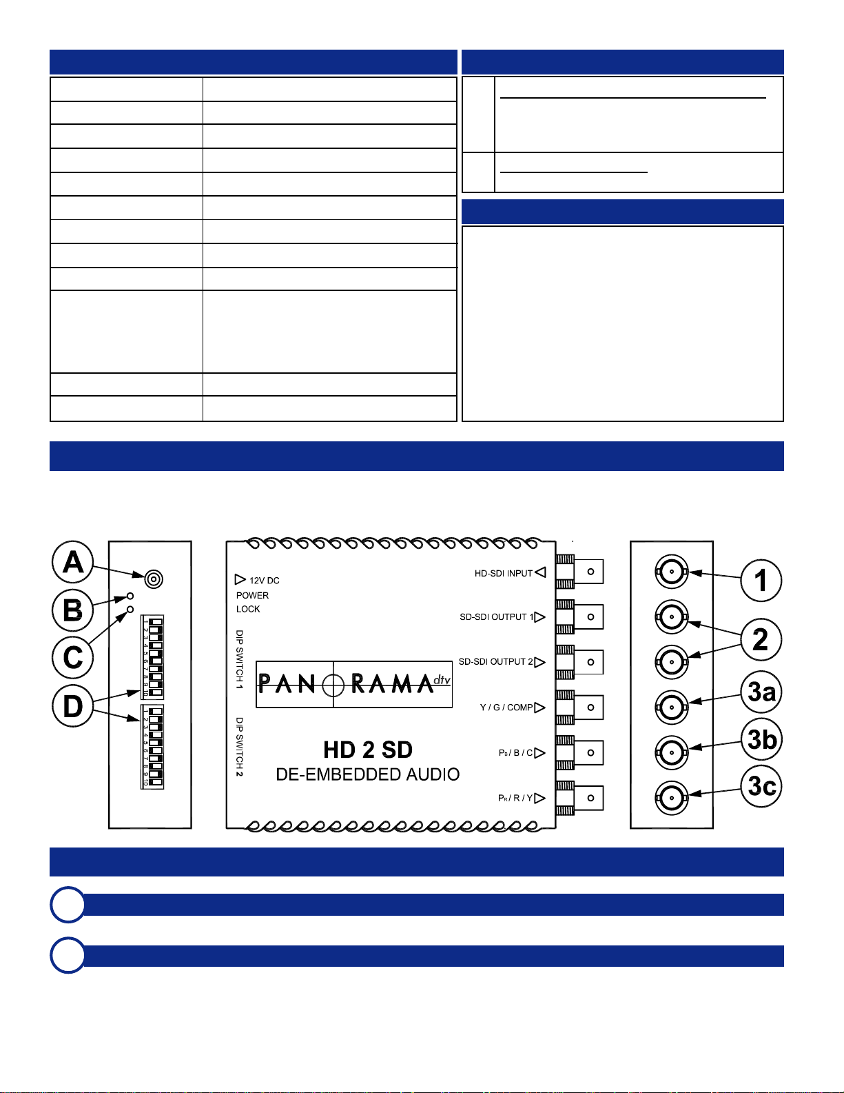
HD/SD-SDI Input
This connector accepts high-definition HD-SDI signals to be down-converted to SD-SDI signals.
SD-SDI Outputs (1 and 2)
Each of these two unbalanced BNC connectors output SD-SDI video signals down-converted from the HD-SDI signal
entering the unit at the input (Item 1). Each connector outputs the same signal. Note that when the unit is set to output
audio test tones, the audio signals are embedded and output from these connectors.
HD2SD Front Panel Features
Please refer to the diagram below to familiarize yourself with the front and rear panel features of the HD2SD unit. The sections
on the following pages describe these features and are referenced, by number for front panel and letter for rear panel, to the
diagram below.
Input Signal:
Input Connector:
Output Signal (digital):
Output Connector (Digital):
Output Signal (Analog):
Output Connector (Analog):
Video DAC:
SD-SDI Over-Sampling:
Audio Pass-Through:
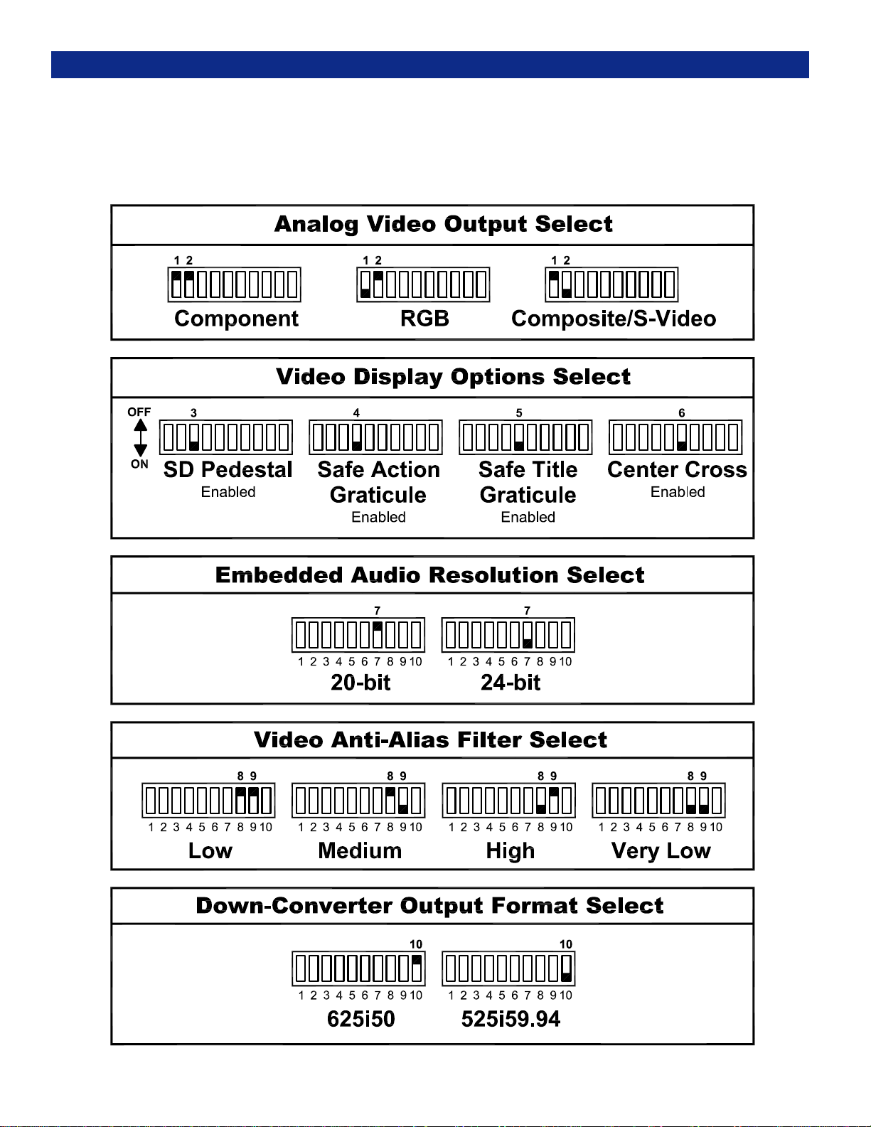
Selectable Parameters
(x2 10-Position DIP
Switch Modules):
Power:
Dimensions:
HD-SDI
x1 female BNC, 75 Ohms
SD-SDI
x1 female BNC, 75 Ohms
Component, RGB, or Composite/S-Video
x3 female BNC, 75 Ohms
10-bit
16x
20-bit or 24-bit
EDH, 4:3/16:9/14:9 safe action/title graticule,
SD pedestal, audio resolution: 20/24-bit, anti-
alias, SD out format: 625i50/525i59.94,
anamorphic/letterbox output, raster/graticule
output aspect ratio, 31 video test patterns,
and audio test tones.
12 VDC external power supply (optional)
4 x 3.4 x 1” (111 x 101 x 27mm)
General Specifications
HD:
SD:
SMPTE 292M/274M/296M @ 1.485and1.435 Gb/s
-1080i @ 60/59.94/50 Hz
-1080p/psf @ 30/29.97/25/24/23.98 Hz
-720p @ 60/59.94/50/30/29.97/25/24/23.98 Hz
SMPTE 259M @ 270 Mb/s
-625i/50, -525i59.94
Supported Video Formats
Video Test Patterns: 100% color bars, 75% color bars, 100% color
bars and red, check-field matrix, 4:3 square, 16:9 square, 5 step
staircase,valid5stepmodulatedstaircase,limitramp, shallow ramp,
multiburst60%sweepwithmarkers,fullfieldline17ITS,convergence,
tartanbars,1fieldin8white,white,black,red,green,blue,magenta,
cyan,staticxfrequencysweeplozoneplate,staticxfrequencysweep
hi zoneplate, static y frequency sweep zoneplate, moving x bars
zoneplate,movingybarszoneplate, moving xy bars zoneplate,static
circular zoneplate, & moving circular zoneplate.
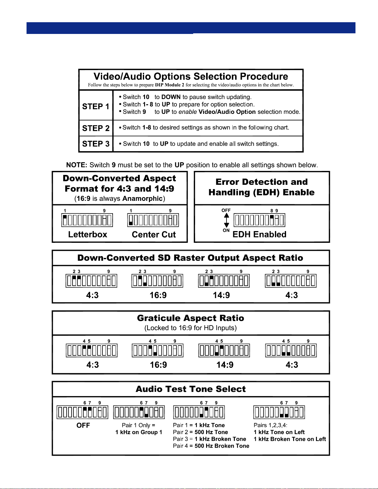
Audio Test Tones: (1 kHz on Pair-1/Group-1) (1kHz on P1,
500HzonP2,1kHzbrokenonP3,500HzbrokenonP4) (1kHz
on left, 1 kHz broken on left for pairs 1/2/3/4)
Video and Audio Tests
HD2SD Front/Rear Panel Features