63062506_201803.indd
Installation instructions
Solar pump assembly 10E / 20E
GB
Installation location The solar pump assembly is to be installed in the solar return line.
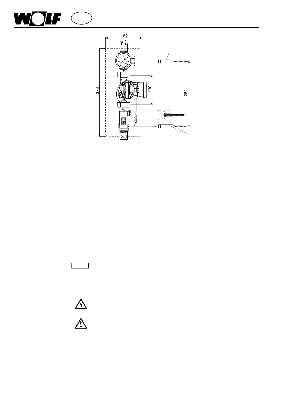
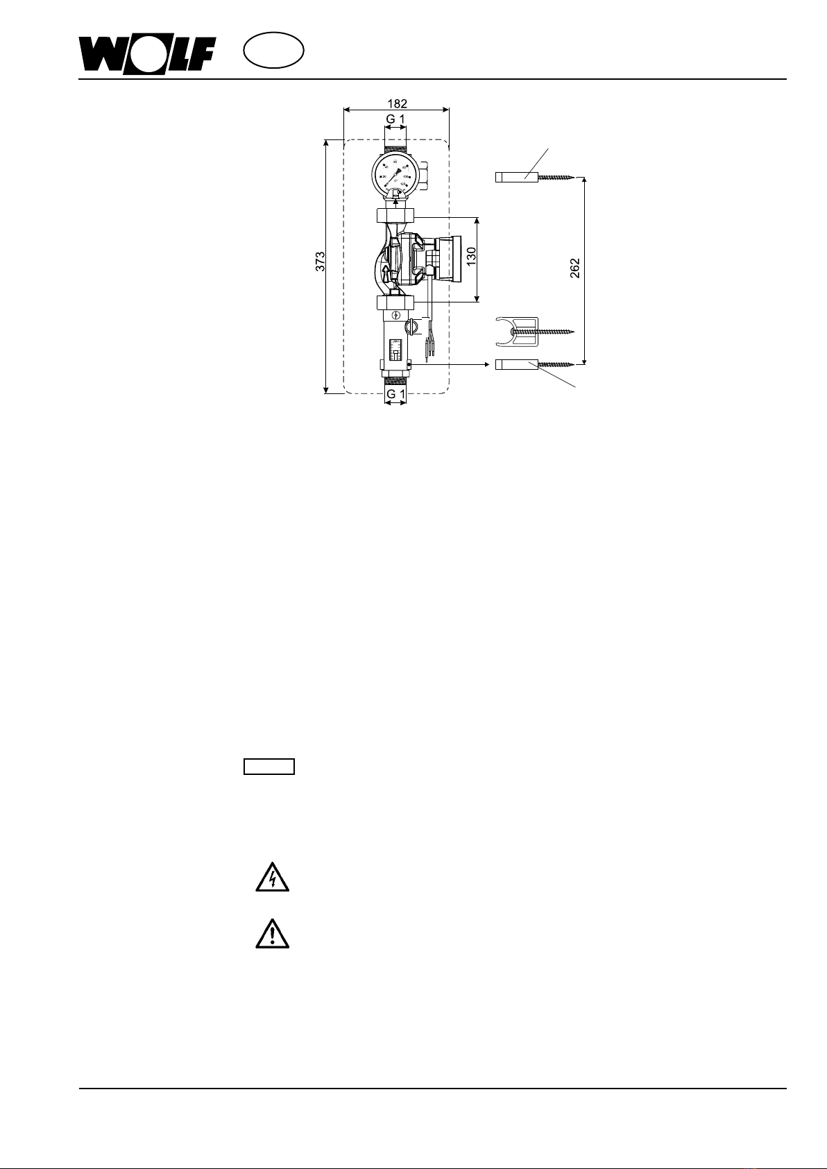
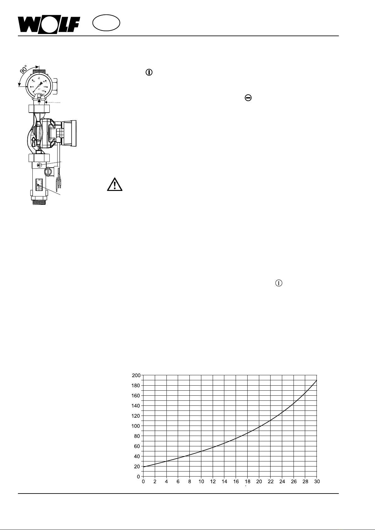
Connection dimensions
installation of the
connecting lines
- Use clamping ring unions to t the pipes of the solar heating system to the upper and
lower connections. Insert the pipe ends, cut off at right angles and deburred, as far
as they will go and use an open-ended spanner to rmly tighten the clamping ring
unions. Counter while tightening.
If copper tubes with a wall thickness of ≤ 1 mm are employed, in particular
soft copper tubes (rolled goods), support sleeves are to be used for additional
stabilisation of the pipes.
Warning
Wall mounting bracket top
Wall mounting bracket bottom
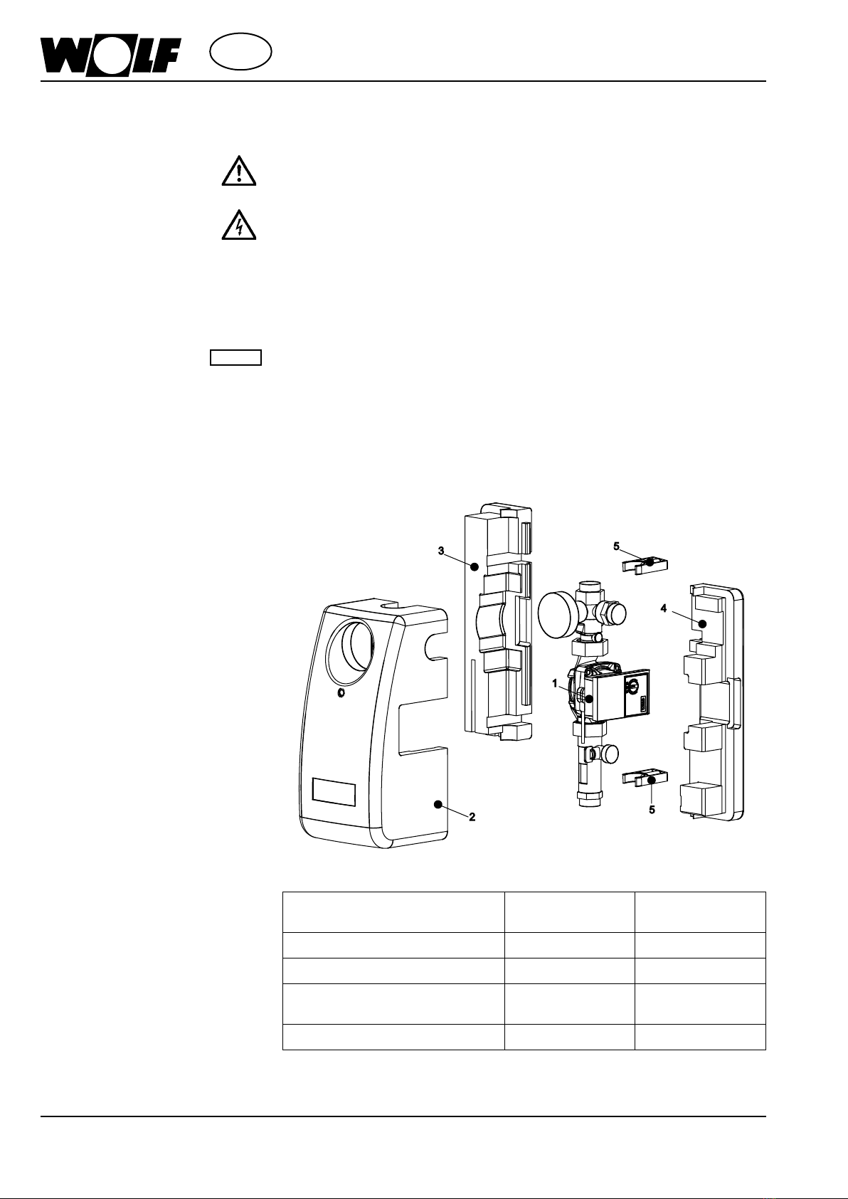
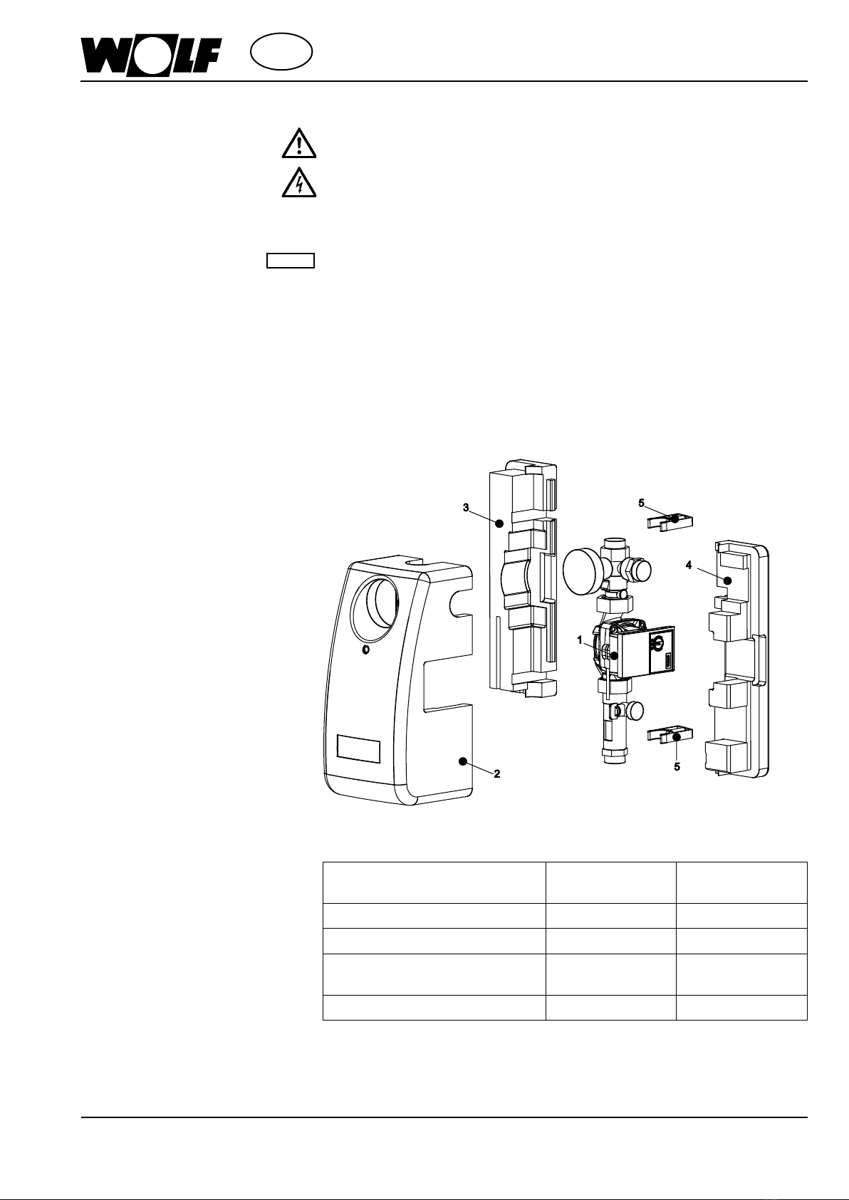
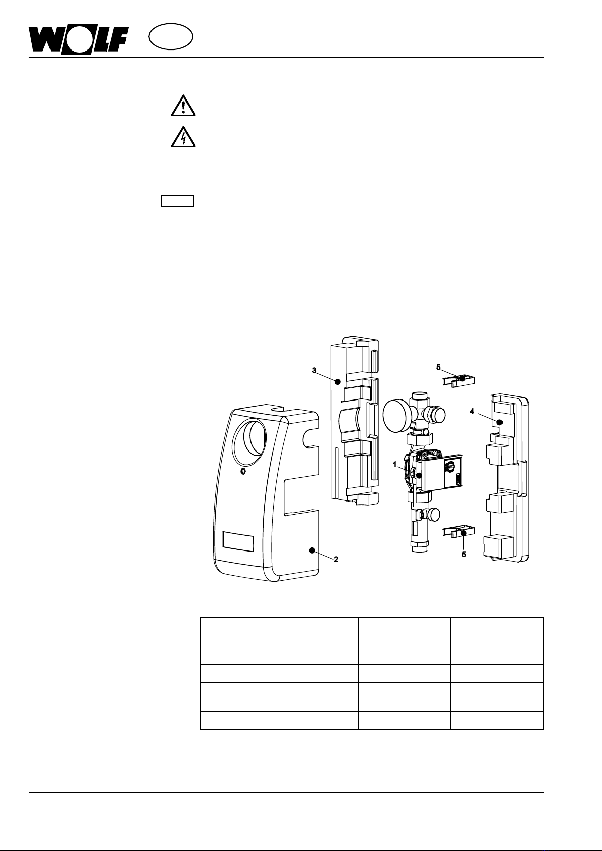
Wall mounting - Take the solar pump assembly out of its packaging and remove the insulating
shells (2, 3 & 4).
- Mark drill holes (spacing between centres 262 mm), drill (Ø 8 mm) and t the
wall plugs.
- Unclip the return branch (1) from the upper and lower wall mounting bracket (5)
- Mount the wall mounting brackets (5) using the screws provided
- Connect the rear insulating shells (3) and (4) together over the wall mounting
bracket
- Clip the return branch (1) back into the wall mounting bracket (6).
Electrical connection
of the circulation pump
- Only specically trained and qualied persons are permitted to work on electrical
components. Pass the connecting cable of the circulation pump through the insulation
and connect as described in the installation instructions for the solar control unit.
There is a possibility of destruction or perilous voltage on the device.
Do not ll the system in strong sunlight, or cover the collectors. There is a risk
of burns! Only use undiluted ANRO to ll the system. The addition of water or
other process media is not permissible. There is a danger of occulation and
protection against frost and corrosion is no longer ensured. This can lead to the
complete failure of the system.
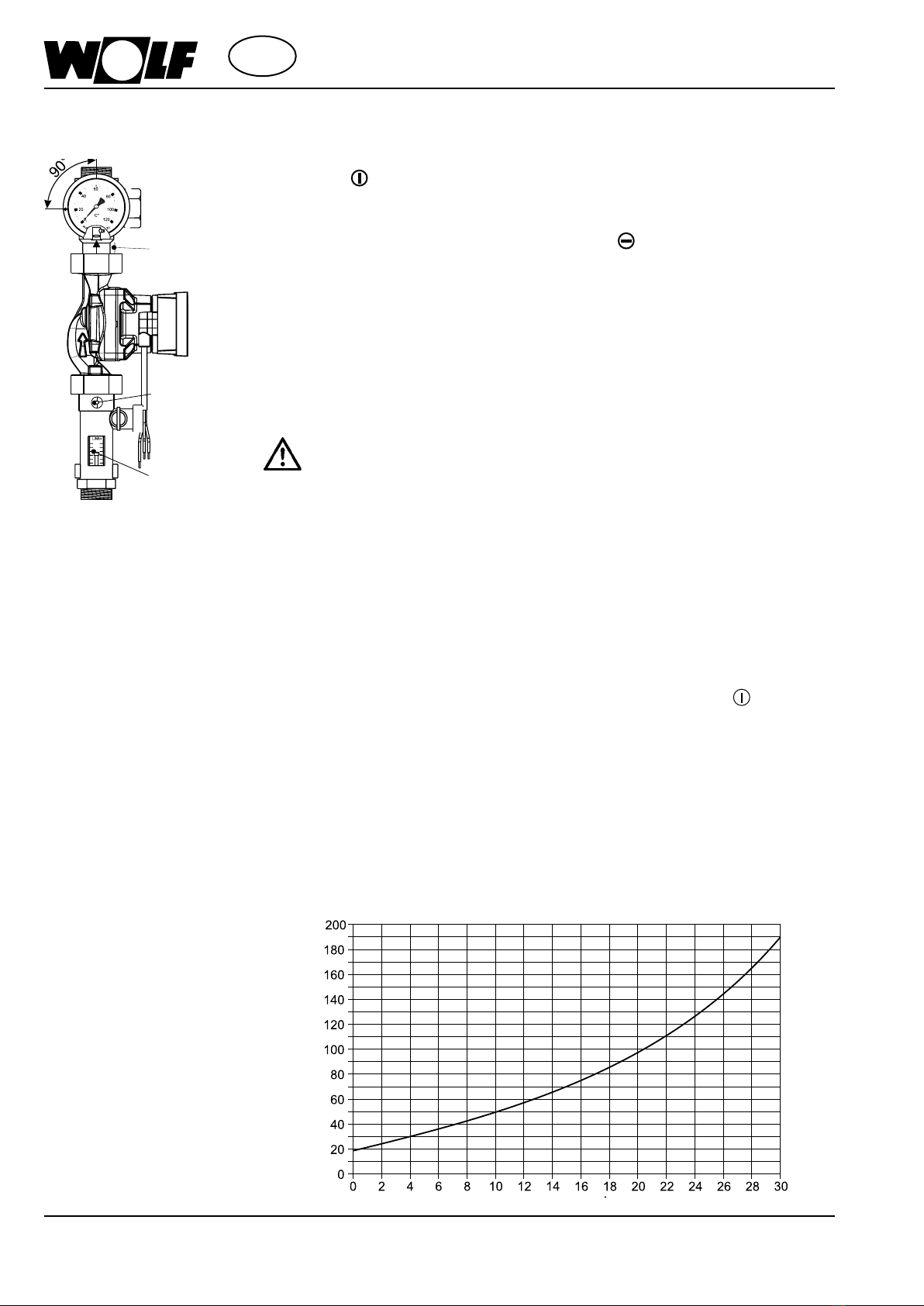
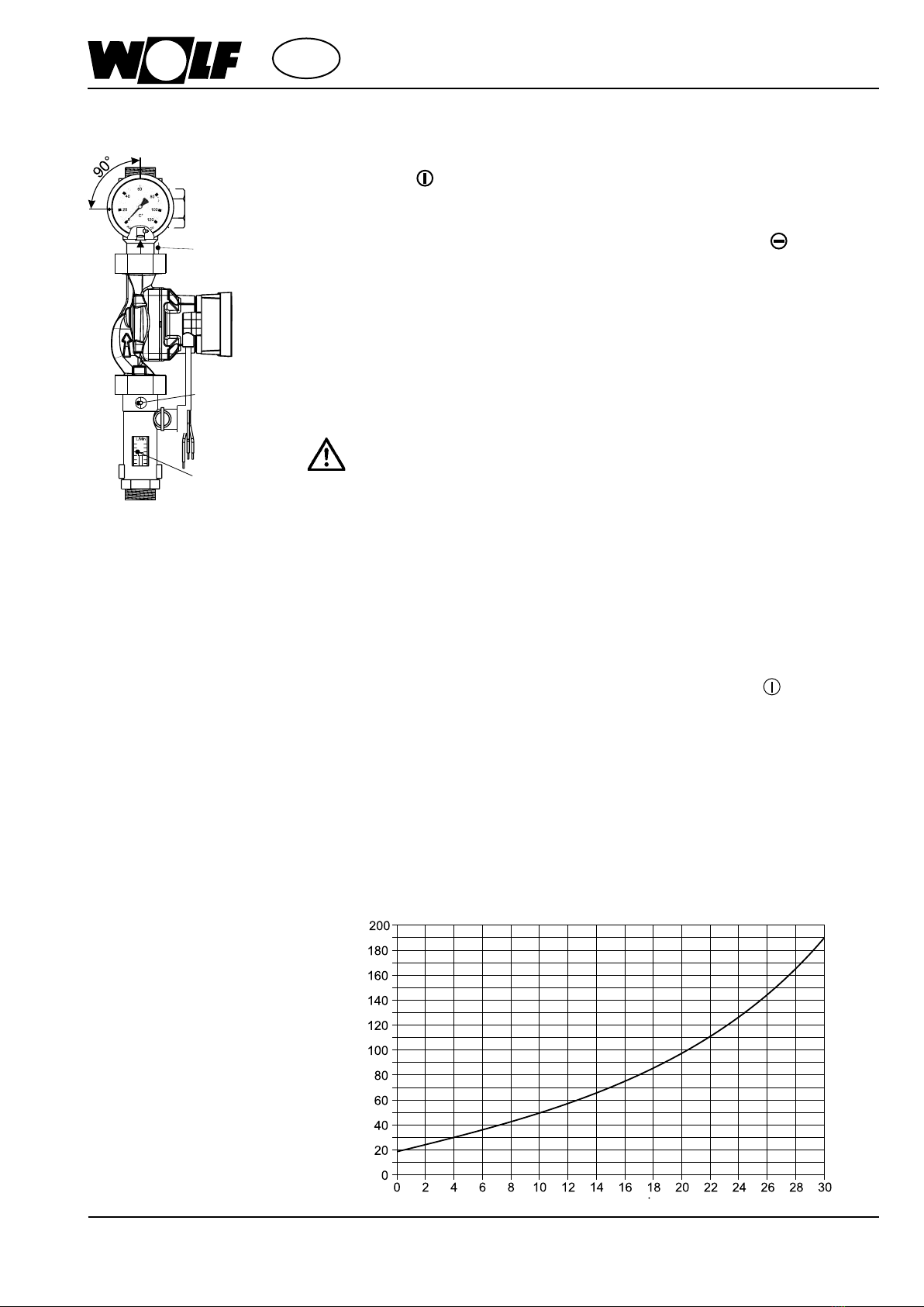
For lling and ushing the solar heating system we recommend the use of a lling and
ushing pump for at least 20 to 60 minutes! The ow velocity must be > 4 m/s in order
to be able to drag along air pockets and contamination. Manual venting can then be
dispensed with.
Filling and ushing the
system