WolfPack HDTVIPH400 User manual

All Rights Reserved
User Manual
Version: HDTVIPH400_2019V1.0
IP Streaming Encoder and Decoder
WolfPack HDTVIPH400

Preface
Read this user manual carefully before using the product. Pictures shown in this
manual are for reference only. Different models and specifications are subject to real
product.
This manual is only for operation instruction, please contact the local distributor for
maintenance assistance. The functions described in this version were updated till
October, 2019. In the constant effort to improve the product, we reserve the right to
make functions or parameters changes without notice or obligation. Please refer to the
dealers for the latest details.
FCC Statement
This equipment generates, uses and can radiate radio frequency energy and, if not
installed and used in accordance with the instructions, may cause harmful interference
to radio communications. It has been tested and found to comply with the limits for a
ClassAdigital device, pursuant to part 15 of the FCC Rules. These limits are designed
to provide reasonable protection against harmful interference in a commercial
installation.
Operation of this equipment in a residential area is likely to cause interference, in which
case the user at their own expense will be required to take whatever measures may be
necessary to correct the interference.
Any changes or modifications not expressly approved by the manufacture would void
the user’s authority to operate the equipment.
IP Streaming Encoder and Decoder

SAFETY PRECAUTIONS
To ensure the best performance from the product, please read all instructions carefully
before using the device. Save this manual for further reference.
Unpack the equipment carefully and save the original box and packing material for
possible future shipment.
Follow basic safety precautions to reduce the risk of fire, electrical shock and injury
to persons.
Do not dismantle the housing or modify the module. It may result in electrical shock
or burn.
Using supplies or parts not meeting the products’ specifications may cause
damage, deterioration or malfunction.
Refer all servicing to qualified service personnel.
To prevent fire or shock hazard, do not expose the unit to rain, moisture or install
this product near water.
Do not put any heavy items on the extension cable in case of extrusion.
Do not remove the housing of the device as opening or removing housing may
expose you to dangerous voltage or other hazards.
Install the device in a place with fine ventilation to avoid damage caused by
overheat.
Keep the module away from liquids.
Spillage into the housing may result in fire, electrical shock, or equipment damage.
If an object or liquid falls or spills on to the housing, unplug the module immediately.
Do not twist or pull by force ends of the optical cable. It can cause malfunction.
Do not use liquid or aerosol cleaners to clean this unit. Always unplug the power to
the device before cleaning.
Unplug the power cord when left unused for a long period of time.
Information on disposal for scrapped devices: do not burn or mix with general
household waste, please treat them as normal electrical wastes.
IP Streaming Encoder and Decoder

Table of Contents
1. Product Introduction...............................................................................................1
1.1 Features .......................................................................................................1
1.2 Package List .................................................................................................1
2. Specification ..........................................................................................................2
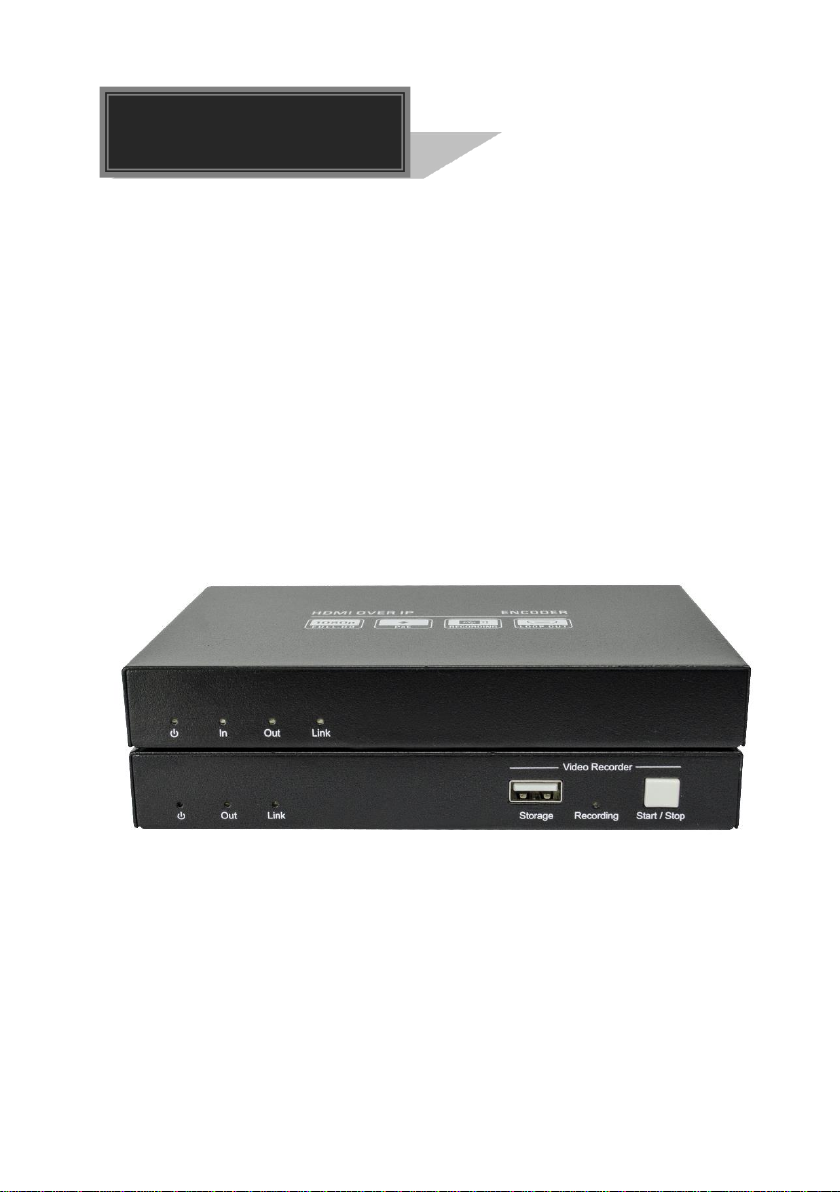
3. Panel Description...................................................................................................3
3.1 IPH400E Encoder..........................................................................................3
3.2 IPH400D Decoder.........................................................................................4
4. System Connection................................................................................................5
4.1 Usage Precaution..........................................................................................5
4.2 Connection Type...........................................................................................5
4.3 System Diagram............................................................................................6
4.4 Hardware Setup............................................................................................7
5. Operation of IP Streaming Management .................................................................8
5.1 General Information.......................................................................................8
5.2 Device Configuration...................................................................................11
5.3 Video Routing Tab.......................................................................................12
5.3.1 Video Switching.................................................................................12
5.3.2 Disconnecting Source from RX...........................................................13
5.3.3 Preset Management...........................................................................14
5.3.4 Multiview Setting................................................................................15
5.4 Audio Routing Tab.......................................................................................16
5.5 RS232 Routing Tab.....................................................................................17
5.5.1 Assign Encoder to all Decoders..........................................................18
5.5.2 Sending RS232 Data from IP Streaming Management to a Device......18
5.6 IR Routing Tab ............................................................................................19
5.6.1 Assign Encoder to all Decoders..........................................................20
5.6.2 Sending IR Data from IP Streaming Management to a Device.............20
5.7 Global Command Options and Settings........................................................21
5.7.1 Decoder (RX) Settings Options ..........................................................21
5.7.1.1. Video Format Setting...............................................................22
5.7.1.2. Device Setting.........................................................................23
IP Streaming Encoder and Decoder

5.7.1.3. Factory Reset .........................................................................25
5.7.1.4. Device Reboot ........................................................................25
5.7.1.5. Firmware Upgrade ..................................................................26
5.7.2 Encoder (TX) Settings Options...........................................................27
5.7.2.1. Device Setting.........................................................................28
5.7.2.2. Video Format Setting...............................................................29
5.7.2.3. Factory Reset .........................................................................30
5.7.2.4. Device Reboot ........................................................................30
5.7.2.5. Firmware Upgrade ..................................................................30
5.8 System Management Tab............................................................................31
5.8.1 Security Settings................................................................................31
5.8.2 System Logs......................................................................................32
5.9 Routing Table..............................................................................................33
6. Panel Drawing .....................................................................................................35
7. Troubleshooting & Maintenance............................................................................36
8. Customer Service.................................................................................................37
IP Streaming Encoder and Decoder

1
1. Product Introduction
transmission with IR&RS232 control signals over IP network. It works with one control
PC (Wake on LAN) and one 1GbE Switch to control a variety of functions.
audio switching, IR&RS232 transmission, video recording, PoE, etc. The control
software “IP Streaming Management” merge all functions for user control the IP
streaming system.
installation, more interoperability and flexibility.
1.1 Features
1080p video over 1G Switch.
Supports resolution up to 1920x1080p.
Supports PoE that the Encoder/Decoder can be powered by IP network.
Supports video recording.
The encoder features HDMI loop out.
Supports audio breakout.
Supports video matrix and multiview.
1.2 Package List
IPH400E
1x IPH400E Encoder (TX)
2x Mounting Ears with 2 Screws
1x 3-pin Terminal Block
IPH400D
1x IPH400D Decoder (RX)
2x Mounting Ears with 2 Screws
1x 3-pin Terminal Block
1x User Manual
Note: Please contact your distributor immediately if any damage or defect in the
components is found.
IP Streaming Encoder and Decoder
The WolfPack HDTVIPH400 is an IP Streaming Encoder/Decoder which is designed for HDMI
The HDTVIPH400 features 1080p HDMI video switching, video matrix, audio de-embedding,
Compares with traditional HDBaseT extender, HDTVIPH400 features low cost, easy

2
2. Specification
Video Input
(1) HDMI In
Video Input Connector
(1) Type-A female HDMI
HDMI Input Resolution
Up to 1080p@60Hz 8bit
Video Output
(1) HDMI Out
Video Output Connector
(1) Type-A female HDMI
HDMI Output Resolution
Up to 1080p@60Hz 8bit
Control
(1) RS232, (1) IR In, (1) IROut, (1) LAN (PoE)
Control Connector
(1) 3-pin terminal block, (2) 3.5mm jack, (1) RJ45
Video Output
(1) HDMI Out
Video Output Connector
(1) Type-A female HDMI
HDMI Output Resolution
Up to 1080p@60Hz 8bit
Audio Output
(1) Audio Out (L+R)
Audio Output Connector
(1) RCA jack
Control
(1) Storage, (1) RS232, (1) IR In, (1) IR Out,
(1) LAN (PoE)
Control Connector
(1) Type-A USB, (1) 3-pin terminal block,
(2) 3.5mm jack, (1) RJ45
General
External Power Supply
Input: AC 100~240V, 50/60Hz, Output: 12V DC 1A;
PoE supported.
Power Consumption
Encoder:4W (Max); Decoder:3.5W (Max)
Operation Temperature
-5℃~ +55℃
Storage Temperature
-25℃~ +70℃
Relative Humility
10%-90%
Dimension (W*H*D)
152.0mm x 21.0mm x 100.0mm
Net Weight
Encoder: 340; Decoder: 345g
IP Streaming Encoder and Decoder
WolfPack HDTVIPH400E
WolfPack HDTVIPH400D

3
3. Panel Description
①POWER LED: The LED illuminates green when power is applied.
②In LED: The LED indicates blue when the encoder detects HDMI source input.
③Out LED: The LED indicates blue when the HDMI Out port is connected to display
device.
④Link LED: The LED illuminates blue when there is a valid LAN link between the
encoder and the decoder.
⑤HDMI In: Type-Afemale HDMI port to connect HDMI video source device.
⑥HDMI Out: Type-A female HDMI port to connect HDMI display device.
⑦RS232: 3-pin terminal block for RS232 routing control. Supports point to point
unicast and point to multipoint broadcast configuration.
⑧IR IN: 3.5mm jack to connect an IR receiver for IR routing control.
⑨IR OUT: 3.5mm jack to connect an IR emitter for IR routing control.
⑩LAN (PoE): RJ45 port to connect directly to the decoder or a network switch using
a CATx cable.
⑪DC 12V: DC port for AC power adapter connection.
IP Streaming Encoder and Decoder
3.1 WolfPack HDTVIPH400E Encoder

4
①POWER LED: The LED illuminates green when power is applied.
②Out LED: The LED indicates blue when the HDMI Out port is connected to display
device.
③Link LED: The LED illuminates blue when there is a valid LAN link between the
encoder and the decoder.
④Storage: Type-A USB to connect U-disk for video recording.
⑤Recording LED: The LED indicates blue when recording video.
⑥Start/Stop Button: Press the button to start or stop video recording.
⑦HDMI Out: Type-A female HDMI port to connect HDMI display device.
⑧Audio Out: RCAjack to connect audio output device.
⑨RS232: 3-pin terminal block for RS232 routing control. Supports point to point
unicast and point to multipoint broadcast configuration.
⑩IR IN: 3.5mm jack to connect an IR receiver for IR routing control.
⑪IR OUT: 3.5mm jack to connect an IR emitter for IR routing control.
⑫LAN (PoE): RJ45 port to connect directly to the encoder or a network switch using
a CATx cable.
⑬DC 12V: DC port for AC power adapter connection.
IP Streaming Encoder and Decoder
3.2 WolfPack HDTVIPH400D Decoder

5
4. System Connection
4.1 Usage Precaution
Make sure all components and accessories are included before installation.
The system should be installed in a clean environment with proper temperature and
humidity.
All of the power switches, plugs, sockets, and power cords should be insulated and
safe.
All devices should be connected before being powered on.
4.2 Connection Type
There are five types of possible applications:
Extender (Point-to-Point)
In a point-to-point configuration, there is no need for a switch. Distribute full,
uncompressed data up to 1080p@60Hz resolution and RS232, IR control signals over
a single fiber cable.
Splitter (One-to-Many)
With only one encoder and one 1G Ethernet switch, anyA/V signal can be flawlessly
and instantly distributed to a near limitless number of decoder and screens, any
number of times.
Matrix Switcher (Many-to-One, Many-to-Many)
The combination of switching and splitting enables a completely scalable matrix
system. Independently route video, audio and RS232, IR control signal from any source
to any endpoint. The IP streaming system allows for on-the-fly upgrading and a virtually
unlimited number of I/O ports.
IP Streaming Encoder and Decoder

6
4.3 System Diagram
The following diagram illustrates typical input and output connections that can be
utilized with the IP streaming encoder/decoder:
IP Streaming System
IP Streaming Encoder and Decoder

7
4.4 Hardware Setup
The IPH400 set you have received include one encoder (TX) and one decoder (RX).
Please follow the steps below to complete the system installation:
1) Connect the video/graphics source device to the HDMI input connector on each TX
unit.
2) (Optional) Connect the video display device to the HDMI output connector on each
TX unit.
3) Connect the video display device to the HDMI output connector on each RX unit.
4) (Optional) Connect audio output device (e.g. speaker or headphone) to the audio
output connector of the RX if you want to test additional audio extension.
5) (Optional) Connect RS232 devices as needed if you want to test RS232 serial
extension between TX and RX units.
6) (Optional) Connect compatible IR emitter modules to the IR output connectors of
any TX or RX.
7) (Optional) Connect compatible IR receiver modules to the IR input connectors of
any TX or RX.
8) Connect a 1G Ethernet cable (Cat-6a recommended) from the 1GbE LAN port
each TX and RX unit to any available 1GBaseT port.
9) Connect the control PC to the LAN port of any IPH400E / IPH400D device or to a
Cat-x port of the 1GbE switch (except the management/console port of the switch).
10) The hardware setup is now complete.
Note that any TX can also be connected directly to a RX without the 1GbE switch in
the middle using fiber cable or Cat-x cable to test point to point functionality.
IP Streaming Encoder and Decoder

8
5. Operation of IP Streaming Management
5.1 General Information
The IP Streaming Management is a demonstration control software used to configure
and control signal extension, routing and switching between TX and RX units.
The IP Streaming Management can be used on any Windows PC using Microsoft .Net
framework 4.0 or later Windows version.
Before proceeding, make sure all IP streaming units are powered ON. Then ensure that
the IP addresses of PC and all units are on the same local area network (LAN).
Username: admin
Password: admin
Please type the username and password, and then click Login.
IP Streaming Encoder and Decoder
Start the application by double clicking on HDTVIPH400.exe file.

9
Upon launch, the IP Streaming Management’s main interface will appear as shown in
the picture below:
After connecting to the LAN, the IP Streaming Management will show discovered
devices as tiles. There are few things to take note of:
The application features many different tabs to control the HDMI routing, as well as
routing of other signals such as analog audio, RS232 control, etc. The default
current tab should be "Video Switching", meaning that the video source displayed
by an RX device (Decoder).
The top area of the user interface is labeled "Decoder (RX)".All RX devices
detected on the network will appear here.
The bottom area of the user interface is labeled “Encoder (TX)". All TX devices
detected on the network will appear here.
IP Streaming Encoder and Decoder
HDTVIPH400D
HDTVIPH400E

10
Click on at the bottom-left corner to enter system setting interface.
In this interface, you can:
Click “LogOut” to exit the current login account.
Select “Auto Login” to save the current login account for auto-sign in next time.
Select “Initial Page” for system operating easily.
Set the log save days.
Select the “Follow video switch”. When switching video, the audio will automatically
follow the video to switch.
IP Streaming Encoder and Decoder

11
5.2 Device Configuration
Before starting the IP Streaming Management application, make sure it is connected
directly to the network switch on one of the devices (TX or RX). Now launch the
application. Upon launch, the IP Streaming Management main window will open up in
the “Video Switching” tab. It will discover all the TX and RX devices on the network and
display them inside the application.
All connected devices on the network will appear as a gray tiles within the application
window.
Each tile will identify the “Hostname” of the device. The default device “Hostname” is
the IPH400E/IPH400D. Note that the “Hostname” can be updated at any time. The “IP
Address” of the device is also indicated within the tile.
If a source device is connected to the video port of the TX, a picture illustrating a
source device will appear within the respective tile along with information about the
video feed. Similarly, if a display device is connected to the RX, an illustration of a
display will appear within the corresponding RX tile. If no device is visible within the tile,
it means that the device is connected and detected but no source (or display) device is
connected to the TX (RX).
TX device tile info
RX device tile info
IP Streaming Encoder and Decoder

12
5.3 Video Routing Tab
The "Video Routing" tab is used to manage signal routing between TX and RX devices.
All RX devices are listed in the top half of the "Decoder (RX)" section. Similarly, all TX
devices are listed in the bottom half, in the "Encoder (TX)" section.
5.3.1 Video Switching
Joining the RX to TX.
a) In the Encoder (TX) section, select a TX by clicking on its associated active tile
using the left mouse button.
b) Hold down the left mouse button and drag the TX tile over the RX tile it is to be
joined with. Then release the mouse button to drop the TX tile onto the RX tile.
c) TX and RX are now joined.
The video source connected to the Encoder (TX) now appears on the display
connected to the respective Decoder (RX).
If the video is not being displayed, please verify the following:
Ensure that the network switch has been properly configured.
Confirm that the display can support the input source resolution.
IP Streaming Encoder and Decoder

13
Verify that the HDMI cable being used is of good quality. This is particularly
important for high-bandwidths of up to 1080p@60Hz resolution, requiring a "HDMI
Premium High Speed" cable.
To assign a different input source to a Decoder (RX), repeat the steps mentioned
above, dragging a different TX over an RX to associate the decoder itself to the new
source device.
5.3.2 Disconnecting Source from RX
To disconnect a Decoder (RX) from an Encoder (TX) source, right click the menu icon
of the respective RX tile and select "Leave Video Channel".
IP Streaming Encoder and Decoder

14
5.3.3 Preset Management
To rename a preset, delete a stored preset or save the current video switching setting,
recall a saved preset by selecting preset #1~9 and click the gear icon to select the
desired option: Rename, Clear Preset, Save Preset, Recall Preset.
IP Streaming Encoder and Decoder

15
5.3.4 Multiview Setting
The system supports multiview setting, and up to 16 screens to display.
All encoders and decoders show on the device list on the right sidebar block.
Drag and drop the desired encoder/decoder unit over the screen block it is to be
displayed.
Click to set full screen, and click to clear the current screen.
IP Streaming Encoder and Decoder
Table of contents