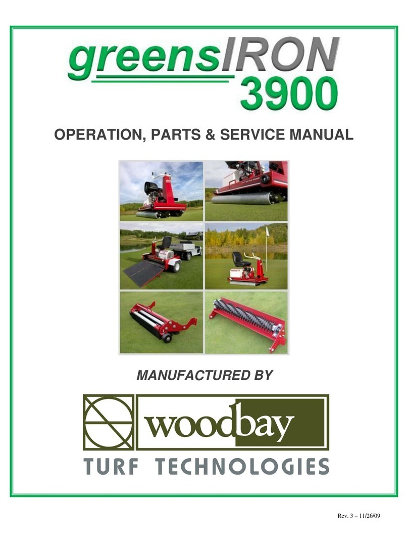
Woodbay greensIRON 6200 User manual

greensIRON 6200
BOWLING GREEN ROLLER
OPERATION, SERVICING & PARTS MANUAL
Manufactured Exclusively by


1
PRESIDENT’S MESSAGE
On behalf of Wood Bay Turf Technologies and your local distributor
of our lawn bowling maintenance products, we welcome you as a new
greensIRON 6200 owner. You are rolling in the right direction.
Introducing a greensIRON into your turf maintenance program will
provide many important benefits. Our engineers who designed the
latest greensIRON were thinking about you. We’ve met the challenge
by working with greens keepers, to smooth their green surfaces for
bowls, to increase green speed, to decrease mowing frequency, to
repair the playing surface after aeration and/or top dressing and to
allow an increase in mowing heights to reduce turf stress.
We urge you to read this manual carefully. The instructions and
recommendations outlined will help assure safe and enjoyable use of
this equipment.
Thank you for choosing the greensIRON 6200.
D. Lyall Adams
President
INTRODUCTION
The purpose of this manual is to provide you with reference information and assistance in setting up,
adjusting and operating your greensIRON 6200 in a safe, effective and efficient manner. It is intended for
turf rollers with a hydrostatic transmission. We hope that it will answer most of your immediate questions,
but we encourage you to contact Wood Bay Turf Technologies on our toll free telephone line (available in
North America at 1-800-661-4942) or the local distributor for further assistance.
The manual alerts you to safety considerations, features of the greensIRON, normal operations including
ironing techniques, adjustments in speeds, servicing, troubleshooting and provides a replacement parts list.
Please note that the information, illustrations and specifications contained in this manual are based on the
latest product information available at the time of printing. Wood Bay Turf Technologies reserves the right to
make changes at any time, without notice, in specifications and models and also to discontinue models. The
right is also reserved to change any specifications or parts at any time without incurring any obligation to
install the same equipment on models manufactured prior to the date of such change.
The illustrations used in this manual may not depict actual models or equipment and are intended as
representative views for reference only.

2
TABLE OF CONTENTS
SECTION PAGE
1 WARNINGS – SAFETY CONSIDERATIONS …………………..…… 3
2 MAJOR COMPONENT DESCRIPTIONS ………………………..….. 4
3 FEATURES……………………………………………………………….. 5
4 OPERATION …………………………………………………..………… 6
BEFORE STARTING ..……………………………..……………… 6
STARTING ENGINE …………………………………..…………… 6
PEDAL CONTROL ………………………………………………… 7
STEERING …………………………………………………..………. 7
LOADING/UNLOADING …………………………………......…… 7
IRONING TECHNIQUES AND PRACTICES …………….…….. 8
5 SERVICING …………………………………………………..…………. 9
6 TROUBLE SHOOTING …………………………………..……………. 10
7 PARTS LIST AND ILLUSTRATIONS ……………………..……….… 11
8 WARRANTY………………………………….……………….………… 27

3
SECTION 1
WARNINGS-SAFETY CONSIDERATIONS
PLEASE OBSERVE ALL WARNING STICKERS ON THE EQUIPMENT.
WARNING INDICATES A STRONG POSSIBILITY THAT EQUIPMENT DAMAGE OR
PERSONAL INJURY COULD OCCUR.
*
WARNING
Do not use your foot, by dragging it on the turf or pushing it against the ditch
board or fence as a method of braking or slowing down the greensIRON
.
Never use your foot to push off from the edge of a bowling green.
*
WARNING
Know how to stop the engine quickly, and understand the operation of all
controls. Never permit anyone to operate the greensIRON
without proper
instructions.
*
WARNING
Do not over fill the fuel tank. There should be no fuel in the filler neck. If any
fuel is spilled, clean it up completely and allow petroleum vapor to dissipate
before starting the engine. Refuel in a well-ventilated area with the engine
stopped; do not smoke or allow a flame or sparks in the area. Gasoline is highly
flammable and explosive under certain conditions. Close the filler cap securely.
*
WARNING
The exhaust muffler becomes very hot during operation and remains hot for a
period of time after stopping the engine. Be careful not to come in contact with
the exhaust muffler while it is hot.
*
WARNING
Children or passengers must not be allowed to ride on the unit.
*
WARNING
Start and stop the engine from a seated position when possible, and ensure both
pedals are in the neutral position to avoid unexpected movement.
*
WARNING
Be aware of the conditions you are operating under. The greensIRON may
have less traction on wet, or on higher cut turf.
*
WARNING
Ensure that the engine is shut off and disabled prior to servicing any component
under the safety guards, transmission, engine coupler, or the engine itself.
*
WARNING
Wear suitable protective clothing so as to prevent eye or ear impairment or loss.
*
WARNING
Sudden release of a clutch pedal on a hydrostatic model will result in a sudden
stop of the greensIRON.
*
WARNING
Drive the greensIRON up and down ramps carefully on to the bowling green
surface; use the trolley to transport greensIRON to the edge of the green.
*
*
WARNING
WARNING
Do not operate the greensIRON over a plinth board protruding above the
surface of the green.
Do not operate the greensIRON on concrete surfaces.
TO VALIDATE WARRANTY FILL OUT AND RETURN TO WOOD BAY TURF TECHNOLOGIES
THE SAFETY ACKNOWLEDGEMENT AND WARRANTY FORMS (see Page 21).

4
6 7
5
19
4
3
2
1
12
11
8
14
1
9
13 12
greensIRON
5000
10
13
12
16
17
15 1
3 18
SECTION 2
MAJOR COMPONENT DESCRIPTIONS
FRONT
1Throttle Control (on mechanical transmission units only) c/w
Soft Hand Grip
2Steering System (handle bar adjustment lever)
3Honda GX160 HX 5.5 hp Engine
4Manual Recoil Starter
5Engine Switch (ON/OFF) & Oil Alert
6Steering Rollers
7Drive Roller (Super Track Vulcanized Coating)
SIDE
8High Back Adjustable Seat c/w
Drain Hole
9Steering Column Cowling and
Cover
10 Transmission Cover
11 Drive Chain and Sprocket
12 Trolley Lifting Lug
13 Drive Roller Bearing
14 Super Track (disperses water)
TOP
15 Aluminum Non Slip
SafetyDeck Surface
16 Right Direction Pedal
17 Left Direction Pedal
18 Seat Adjustment Lever

5
SECTION 3
FEATURES
♦Engineered for ease of operation from start to finish.
♦Unique steering system allows operator to maneuver with ease across green.
♦High back padded seat with slide adjustment for maximum operator comfort and back support.
♦Handle bar adjustment lever for increased operator steering control.
♦Low maintenance hydrostatic transmission and hydraulic motor.
♦Machined and tapered high carbon steel steering rollers give maximum durability and beautiful
manicured bowling greens.
♦Super Trac vulcanized covered drive roller provides excellent traction and produces a soft touch effect to
turf surfaces and bowl roll.
♦Industrial bearings, with easy access to grease ports.
♦Honda GX160 HX 5.5 hp engine with oil alert.
♦greensIRON trolley for transporting the roller from the storage building to the edge of the green.
♦Easy access to hydrostatic transmission and drive chain adjustments.
♦Oil drain hose for convenient servicing of Honda motor.
♦Tiny Tach hour / RPM meter to assist in maintaining accurate maintenance schedules.
♦Three year warranty on parts and labor – “Best in the Industry”.
♦ENGINEERED FOR DURABILITY; BUILT TO LAST!
Having a greensIRON 6200 is rolling in the right direction!

6
SECTION 4
OPERATION
BEFORE STARTING YOUR greensIRON 6200 TURF ROLLER
Refer to your Honda engine, and Hydro-Gear hydrostatic pump owner’s manuals for startup and break-in
recommendations.
Check oil level in engine and transmission reservoir (oil tank).
Check oil type and level in hydrostatic transmission reservoir sight glass and ensure that the fluid is not
discolored and that only Mobil 1 Synthetic 15/30 SAE oil is used.
Check fuel level (unleaded fuel is recommended).
Check drive chain adjustment. Chain may require adjustment (eg., tightening) after initial use.
Check on both sides of the greensIRON to ensure there are no obstructions (eg., gravel/stones) that could
impact on the roller covering.
STARTING ENGINE
Turn the fuel switch to the ON position.
Turn the engine switch to the ON position.
Engage the choke switch if required.
Pull the starter recoil handle (it is recommended that the operator start the engine while seated on the
greensIRON). Keep feet off foot pedals.
Once the engine is running, shut off the choke switch and adjust the throttle speed.
Set the throttle speed with the manual throttle lever located on the engine.
To shut down the engine, switch motor to OFF
position, and shut OFF the fuel switch.
1Fuel switch
2Choke
3Manual throttle lever
4Engine switch
5Pull start handle

7
greensIRON
5000
SECTION 4 (con’t)
PEDAL CONTROL
•Depress the foot pedal for desired direction of travel; left pedal for left travel; right pedal for right travel.
For increased speed, press the pedal down further.
•When stopping, ease back on the foot pedal. CAUTION: Sudden foot pedal release will result in an
IMMEDIATE stop, which could bruise the green. When both pedals are in neutral, the roller will not
move.
•Do not “jam” a foot pedal down quickly to start the turf roller in motion. This will cause the drive roller
to abruptly start and potentially “burn” the turf.
STEERING
Pushing the left handle bar away from the operator will pivot the front of
the steering rollers away from the deck. This will cause the greensIRON
to commence a turn to the right when rolling in that direction, or to the
left when moving in the opposite direction.
Pushing the right handle bar away from the operator will pivot the back of
the steering rollers away from the deck. This will cause the greensIRON
to commence a turn to the left when rolling to the right, or to the right
when rolling to the left.
Avoid over steering to prevent the possibility of bruising the turf.
Always have the greensIRON 6200 in motion when undertaking
turning maneuvers to prevent unnecessary turf damage (bruising the
grass).
LOADING AND UNLOADING
•To transport the greensIRON 6200, hook the
trolley arms under the trolley lift lugs located on
both sides of the deck and press downward on the
trolley handlebars to raise the greensIRON off
the ground. Maneuver in the direction desired.
•Avoid taking the trolley on to a bowling green
surface as the tires may damage the turf surface.
If the trolley must be taken on to the bowling
green, avoid making sharp turns.
•Ensure the transport trolley is removed away from the greensIRON before starting up the engine.
•Ideally, to eliminate the need for taking the trolley on to a bowling green, the operator should use a
shallow sloping ramp suitably fixed to the back boards and then carefully drive the greensIRON 6200 on
to and off the playing surface.

8
SECTION 4 (con’t)
IRONING TECHNIQUES & PRACTICES
•The most efficient rolling pattern requires the operator to
make the first pass straight up the bowling green along
one edge of the plinth board, then return on the second
pass at a slight angle with the front end of the roller
coming to the place where the back end of the roller had
previously been at the start of the first pass. This
procedure should then be repeated until the entire green
has been rolled in this fashion.
•A recommended practice is to alter the rolling pattern
from one day to the next so that the rolling paths cross
over each other (i.e., if the pattern was run longitudinally
on the green one time, it should be run laterally on the
green the next time). Roll the green in the opposite
direction of play.
•When operating on turf that is wet, accelerate with
caution to avoid spinning the drive roller and damaging
the turf.
•Optimum rolling effect will be obtained at a rolling speed of about 1,000 square feet per minute (3 to 5
MPH).
•Always have the greensIRON in motion when undertaking turning maneuvers (not stationary).
•DO NOT REFUEL THE greensIRON WHILE ON THE GREEN SURFACE.
•DO NOT TAKE THE TROLLEY ON TO THE PLAYING SURFACE IF AT ALL POSSIBLE.
•DO NOT LEAVE THE greensIRON SITTING ON THE TURF FOR AN EXTENDED PERIOD
OF TIME (rollers will leave marks).

9
SECTION 5
SERVICING
PRIOR TO SERVICING YOUR greensIRON 6200, SHUT OFF ENGINE.
CAUTION: GASOLINE AND OIL SPILLED OR TRACKED ON TO TURF SURFACE
MAY CAUSE SEVERE DAMAGE.
ENGINE AND CRANKCASE
•Refer to your Honda owner’s manual.
TRANSMISSION
•Refer to your Hydro-Gear hydrostatic transmission owner’s manual.
DRIVE CHAIN ADJUSTMENT
•WARNING: Before opening transmission cover, ensure engine is shut off.
•The idler sprocket can be adjusted in the direction needed to increase or reduce the chain tension. The
chain should have a 3/8” to 1/2” deflection on the bottom under normal operating conditions.
•If it is no longer possible to tighten the chain as needed, remove a half link or a full link to shorten the
chain.
THROTTLE LEVER (on the Honda Engine)
•Check that the lever remains in the chosen speed position when set, and tighten setting if needed.
GREASE FITTINGS
•All bearings have been pre-packed with grease. If necessary, bearings should only be greased sparingly.
STEERING ROLLERS AND HANDLE BARS
•Check periodically the steering roller/handle bar lever for correct alignment.
•Steering rollers must be aligned parallel with the right deck edge. The handle bar in neutral or driving
position must be at right angles (90°) to the steering rollers. The handle bar alignment can be adjusted by
increasing or decreasing the length of the steering rod arm connector assembly under the deck. Making
an adjustment requires disconnecting of at least one rod end, releasing the jam nut, and turning the rod
end toward or away from the other rod end on the connector assembly.
ROLLERS
•Inspect the rollers for any dirt or grass clippings and clean them prior to operating the unit on the green.

10
SECTION 6
TROUBLE SHOOTING
TROUBLE SHOOTING SUGGESTIONS
SYMPTOM PROBABLE CAUSE SOLUTION
Engine runs rough.
Choke on.
Dirty air filter.
Intermittent spark.
Improper fuel mixture.
Switch off.
Clean or replace.
Clean or replace spark plug.
Readjust—see engine manual.
Engine cuts out when changing
throttle speed.
Oil level low.
Fuel level low.
Fill to correct level—see engine manual.
Fill fuel tank.
No movement left or right when
pedals are depressed.
Chain is broken.
Replace chain. Adjust as explained in
Section 5.
Jerky motion or chain is jumping.
Not enough tension in chain.
Adjust chain tension as explained in
Section 5.
Pedal movement is either too free
or is difficult to depress.
Tension on nylock nuts for the
linkage arms may need adjustment.
Adjust tension on nylock nuts until a
comfortable pedal motion is obtained.
Rattling, grinding type of noise
from under deck when turf roller
is moving.
Chain may be loose.
A steering or drive roller bearing
may be failing.
Bolts may be loose on moving parts.
If chain is rubbing, ensure it is tightened
and properly aligned.
Tip roller deck on edge and hand turn
rollers to check for noise; grease and/or
replace bearings as needed
Check and tighten bolts as needed on:
•Drive roller pillow blocks
•Pedal linkages
•Steering roller end bolts / housings
•Stopper bolts on top of steering
frame
Roller continues travelling after
release of foot pedals to the
neutral position.
Foot pedal return springs require
adjusting under the deck.
See transmission manual and Section 9
Transmission is running extra hot,
shortly after start up.
Fluid has lost its viscosity (oil has
become dark in color), or the wrong
type or transmission fluid has been
used.
Drain the fluid from the hydrostatic pump
and fill with Mobil 1 Synthetic 15W50
SAE oil.

11
SECTION 7
PARTS LIST AND ILLUSTRATIONS
Trolley Components – Section J
ITEM DESCRIPTION QUANTITY PART NUMBER
1. Trolley Frame Assembly 1 50 N72 190
2. Wheel and Hub Assembly 1 50 N79 194
3. Rest for Trolley 2

12
SECTION 7 (con’t)
Clutch Components - Section K
Item
Description
Quantity
Part #
1
.
Clutch Pedal: Left
1
39 K01 101
2.
Clutch Pedal: Right
1
39 K01 102
3.
Key (3/16” x 1 1/4”)
1
39 Y02 187
4.
Transmission Rocker Arm
1
39 K01 105
5.
Foot Pedal Linkage
2
39 K01 104
6.
Clutch Pedal Bushing
2
39 K01 103
7.
Bearing and Housing (2 hole: 5/8”)
2
39 K02 108
8.
Carriage Bolt (5/16” x 1”)
2
39 Z02 208
9.
Flat Washer (5/16”)
2
39 Z02 203
10.
Lock Washer (5/16”)
2
39 Z02 204
11.
Nut (5/16”) NC
2
39 Z02 205
12.
Rod End (3/8” NF: Female RH)
2
39 Y02 183
13.
Jam Nut (3/8” NF RH)
2
39 Y02 185
14.
15.
16.
17.
18.
Rod End (3/8” NF: Female LH
Jam Nut (3/8” NF LH)
Bolt (3/8” x 1 1/4
” NC)
Lock Washer (3/8”)
Nut (3/8” NC)
2
2
4
4
4
39 Y02 184
39 Y02 186
39 Z02 194
39 Z02 196
39 Z02 197

13
SECTION 7 (con’t)
Body Components
- Section O
Item
Description
Quantity
Part #
1.
Decal Package: Caution
1 set
39 O01 111
2.
Decal Package: Identification
1 set
39 O01 112
3.
Decal Package: Striping
1 set
39 O01 113
4.
Serial Number Plate
1
39 O01 110
5.
Deck (not shown)
1
39 O01 109

14

15
SECTION 7 (con’t)
Steering Column Components - Section P
Item
Description
Quantity
Part #
1.
Handle Bar
1
39 P01 118
2.
Steering Hand Grip
2
39 P02 119
3.
Steering Shaft
1
39 P01 120
4.
Handle Bar Clamp
1
39 P01 121
5.
Handle Bar Adjustment Lever
1
39 P02 122
6.
Steering Arm for Under Deck (welded)
1
39 P01 123
7.
Steering Rod Arm (3/8" x 4 1/4" NF)
1
39 P01 124
8.
Rod End (3/8" Female NF)
2
39 Y02 183
9.
Jam Nut (3/8" NF)
1
39 Y02 185
10.
Bearing and Housing (4-bolt 1.0")
1
39 P02 125
11.
Bearing and Housing (2-bolt 1.0")
1
39 P02 126
12.
Bolt (5 1/6” x 1” Allen Head)
1
39 P02 127
13.
Bolt (3/8" x 1 1/2" NC)
4
39 Z02 194
14.
Lock Washer (3/8”)
7
39 Z02 196
15.
Nut (3/8" NC)
6
39 Z02 197
16.
Flat Washer (3/8”)
1
39 Z02 195
17.
Carriage Bolt (3/8" x 1 1/2" NC)
2
39 Z02 198

16

17
SECTION 7 (con’t)
Steering Roller Components - Section Q
Item
Description
Quantity
Part #
1.
Steering Roller Frame
1
39 Q01 128
2.
Steering Roller
2
39 Q01 129
3.
Stub Axle
4
39 Q01 130
4.
Steering Roller Bearing Plate Spacer
1
39 Q01 131
5.
Flange and Bearing (4-bolt c/w 1" Bearing)
1
39 Q02 132
6.
Bearing (1" c/w set screw collar)
4
39 Q02 133
7.
Pressed Flange (3-bolt)
8
39 Q02 134
8.
Snap Ring (1")
1
39 Q02 135
9.
Bolt (3/8" x 1 1/2" NC)
4
39 Z02 193
10.
Flat Washer (3/8")
8
39 Z02 195
11.
Lock Washer (3/8")
8
39 Z02 196
12.
Nut (3/8" NC)
4
39 Z02 197
13.
Bolt (5/16" x 3/4" NC)
12
39 Z02 202
14.
Flat Washer (5/16")
12
39 Z02 203
15.
Lock Washer (5/16")
12
39 Z02 204
16.
Carriage Bolt (3/8" x 1 1/2" NC)
4
39 Z02 198

18
Table of contents
Other Woodbay Lawn And Garden Equipment manuals
Popular Lawn And Garden Equipment manuals by other brands

EINHELL NEW GENERATION
EINHELL NEW GENERATION NVK 1601 operating instructions

Snapper
Snapper FM7300 Safety instructions & operator's manual

Billy Goat
Billy Goat MV650SPH owner's manual

Agrimate
Agrimate AM-MPT-9D user manual

Hitachi
Hitachi CG40EK owner's manual

SNOWJOE
SNOWJOE SJBLZD-ECM-LED-2 instruction manual