woodmizer MD400 Guide

WARNING! Read and understand this
manual before using this machine.
!
MD400, MD500 Chip Extractor:
Safety, Operation,
Maintenance, and Parts Manual
MD400EA3U MD400EA3U-SYS
MD400EB3U MD400EB3U-SYS
MD500EB5U MD500EB5U-SYS
REV B1.00 - Current
Safety is our #1 concern!
Form #2358-US

Active Patents assigned to Wood-Mizer, LLC
Wood-Mizer, LLC has received patents that protect our inventions which are a result of a dedication to
research, innovation, development, and design. Learn more at: woodmizer.com/patents
©2020 Wood-Mizer LLC
Printed in the United States of America, all rights reserved. No part of this manual may be reproduced in any form by
any photographic, electronic, mechanical or other means or used in any information storage and retrieval system with-
out written permission from
Wood-Mizer, LLC
8180 West 10th Street
Indianapolis, Indiana 46214
&DOLIRUQLD
3URSRVLWLRQ:DUQLQJ
:$51,1*%UHDWKLQJJDVGLHVHOHQJLQHH[KDXVWH[SRVHV\RXWRFKHPLFDOVNQRZQWR
WKH6WDWHRI&DOLIRUQLDWRFDXVHFDQFHUDQGELUWKGHIHFWVRURWKHUUHSURGXFWLYHKDUP
$OZD\VVWDUWDQGRSHUDWHWKHHQJLQHLQDZHOOYHQWLODWHGDUHD
,ILQDQHQFORVHGDUHDYHQWWKHH[KDXVWWRWKHRXWVLGH
'RQRWPRGLI\RUWDPSHUZLWKWKHH[KDXVWV\VWHP
'RQRWLGOHWKHHQJLQHH[FHSWDVQHFHVVDU\
)RUPRUHLQIRUPDWLRQJRWRZZZ3ZDUQLQJVFDJRY
:$51,1*'ULOOLQJVDZLQJVDQGLQJRUPDFKLQLQJZRRGSURGXFWVFDQH[SRVH\RXWR
ZRRGGXVWDVXEVWDQFHNQRZQWRWKH6WDWHRI&DOLIRUQLDWRFDXVHFDQFHU$YRLGLQKDOLQJ
ZRRGGXVWRUXVHDGXVWPDVNRURWKHUVDIHJXDUGVIRUSHUVRQDOSURWHFWLRQ
)RUPRUHLQIRUPDWLRQJRWRZZZ3:DUQLQJVFDJRYZRRG

Table of Contents Section-Page
Table of Contents MD400, MD500 4/14/21 iii
SECTION 1 INTRODUCTION
1.1 About This Manual ................................................................................1-1
1.2 Getting Service....................................................................................... 1-1
SECTION 2 GENERAL SAFETY
2.1 Safety Symbols ...................................................................................... 2-1
2.2 Safety Instructions.................................................................................. 2-1
SECTION 3 SPECIFICATIONS
3.1 Specifications of MD400 and MD500 chip extractors ..........................3-1
3.2 Overall dimensions ................................................................................ 3-3
SECTION 4 SETUP
4.1 Attaching the Chip Extractor ................................................................. 4-1
4.2 Optional Cyclone Twin Bag Collector Assembly.................................. 4-1
SECTION 5 OPERATION
5.1 General Use............................................................................................ 5-1
5.2 Site Preparation...................................................................................... 5-1
5.3 Extractor Operation................................................................................5-1
5.4 Collection System Operation ................................................................. 5-1
SECTION 6 TROUBLESHOOTING GUIDE
6.1 General Troubleshooting........................................................................ 6-1
6.2 Extractor Optimization........................................................................... 6-2
SECTION 7 GENERAL INFORMATION
7.1 How To Use The Parts List.................................................................... 7-1
7.2 Chip Extractor, 3kW 230v Single Phase, 3kW 230v Three-Phase........7-2
7.3 Chip Extractor, 3kW 230v Three-Phase ................................................ 7-3
7.4 Motor/Fan Drive, 3kW, Single-Phase.................................................... 7-4
7.5 Motor/Fan Drive, 3kW, Three-Phase.....................................................7-5
7.6 Motor/Fan Drive, 5.5kW Three-Phase................................................... 7-6
7.7 Motor Starter.......................................................................................... 7-7
7.8 3x4", 1x5" Inlet ...................................................................................... 7-8
7.9 5x4" + 1x5" Inlet.................................................................................... 7-9
7.10 10" Inlet................................................................................................7-10
7.11 8" Outlet ............................................................................................... 7-11
7.12 2x8" Outlet ........................................................................................... 7-12
7.13 10" Outlet ............................................................................................. 7-13
7.14 Mounting Feet...................................................................................... 7-14
7.15 Bagging System ................................................................................... 7-15
7.16 Bag Clamp............................................................................................ 7-17

Table of Contents Section-Page
iv MD400, MD500 4/14/21 Table of Contents

Wood-Mizer® LLC
Limited Product Warranty
Wood-Mizer LLC (“Warrantor”), an Indiana corporation with its principal place of business at 8180 West Tenth Street, Indianapolis, IN 46214-2400 USA, warrants to the purchaser (“Purchaser”) that
for the time periods specifically stated herein and subject to the terms, conditions and limitations stated herein, the equipment manufactured by the Warrantor will be free from defects in material and
workmanship attributable to Warrantor so long as, during the warranty periods stated herein, the equipment is installed, operated and maintained in accordance with the instructions provided by
Warrantor.
* Warranty on Options will match the warranty on the primary equipment when purchased on same invoice.
Exclusions from 90 Day, Limited One Year and Two Year Warranty
Warrantor shall have no responsibility under this warranty for any wear components, including, but not limited to: belts, blade guides, blades, electric motor brushes, drum switches, filters, fuses,
hoses, bearings (excluding cylindrical drive bearings), bushings, cable carriers, and spark plugs. All wear components are furnished “as is”, without any warranty from Warrantor. This limited
warranty does not cover any defects caused by misuse, negligence, alterations, damage due to overload, abnormal conditions, excessive operation, accident, or lack of performance of normal
maintenance services.
Several components which are used in the manufacture of the equipment but not manufactured by Warrantor such as cant hooks, power plants, laser sights, batteries, tires, and trailer axles have
warranties provided by the original equipment manufacturer (written copies available upon request). Warrantor does not separately warrant such items. Components or equipment manufactured by
third parties are not covered by this warranty. Warrantor, however, will provide reasonable assistance to the Purchaser to make claims against any warranties applicable to such component parts as
provided by such original equipment manufacturers. Components or equipment manufactured by third parties are not covered by this Warranty.
Five Year Limited Chassis Warranty
The limited five year chassis warranty described above, DOES NOT extend to (a) any damage stemming from accident, improper towing, overload, abuse, misuse, abnormal conditions, negligence,
excessive operation, or lack of maintenance, (b) rust caused by exposure to corrosive atmospheric conditions, or (c) the sawmill head, carriage, axle, brakes, or any hydraulic or electrical components
attached to the chassis.
Warrantor’s Obligations as To Defects
In the event that the equipment fails to perform due to defective materials or workmanship attributable to Warrantor under normal use and service within the established warranty period, Purchaser’s
sole and exclusive remedy and Warrantor’s sole liability shall be to replace or repair, in Warrantor’s sole and subjective discretion, any defective part at Warrantor’s principal place of business without
cost to the Purchaser if such defect exists. The determination of whether a product is defective shall be made by Warrantor in Warrantor’s sole and subjective discretion. The Purchaser must notify
Warrantor prior to shipping any defective part. Warrantor, at its sole discretion, may cover expenses incurred in shipping the defective part to Warrantor for evaluation; provided, however, that
Warrantor will not be responsible for labor, travel time, mileage, removal, installation or incidental or consequential damages. However, any part in excess of 140 pounds must be returned by the
Purchaser, to the Warrantor’s nearest authorized facility at the Purchaser’s expense, if return is requested by Warrantor. Warrantor shall have a reasonable time within which to replace or repair the
defective part. If Warrantor determines that the product is not defective under the terms of this warranty in Warrantor’s sole and subjective discretion, then Purchaser shall be responsible for any
expenses incurred by Warrantor in returning the equipment to the Purchaser.
Limitations and Disclaimers of Other Warranties
EXCEPT FOR THE EXPRESS WARRANTY PROVISIONS STATED ABOVE, WARRANTOR DISCLAIMS ALL WARRANTIES, EXPRESS AND/OR IMPLIED, INCLUDING WITHOUT
LIMITATION, THE IMPLIED WARRANTIES OF MERCHANTABILITY, AND FITNESS FOR A PARTICULAR PURPOSE, NONINFRINGEMENT AND TITLE. No representation or other affirmation
of fact by representatives of Warrantor, whether verbal or in writing, including photographs, brochures, samples, models, or other sales aids, shall constitute a warranty or other basis for any legal
action against Warrantor. There are no other representations, promises, agreements, covenants, warranties, guarantees, stipulations or conditions, express or implied, by Warrantor except as
expressly set forth herein. THE ORIGINAL PURCHASER AND ANY INTENDED USER OR BENEFICIARY OF THIS EQUIPMENT, SHALL NOT BE ENTITLED TO RECOVER ANY INDIRECT,
SPECIAL, PUNITIVE, EXEMPLARY, CONSEQUENTIAL, SPECIAL, OR INCIDENTIAL DAMAGES OR LOSES, INCLUDING BUT NOT LIMITED TO, DAMAGES OF LOST PRODUCTION, LOST
REVENUE, LOST PRODUCT, LOST PROFITS, LOST BUSINESS, LOSS OF USE, LOSS OF GOODWILL, OR BUSINESS INTERRUPTION, FROM WARRANTOR FOR ANY REASON
WHATSOEVER INCLUDING WITHOUT LIMITATION WARRANTY OR DEFECT IN THE PRODUCT REGARDLESS OF THE SOLE, JOINT AND/OR CONCURRENT NEGLIGENCE, BREACH
OF CONTRACT, BREACH OF WARRANTY, STRICT LIABILITY IN TORT OR STATUTORY CLAIMS OR OTHER LEGAL FAULT OR RESPONSIBILITY OF EITHER WARRANTOR OR
PURCHASER OR ITS EMPLOYEES OR AGENTS. Warrantor does not warrant that its equipment meets or complies with the requirements of any particular safety code or governmental
requirements.
Defective items replaced under the terms of this warranty become the property of Warrantor.
Design Changes
Warrantor reserves the right to change the design of its products from time to time without notice and without obligation to make corresponding changes in or to its products previously manufactured.
Rights of Purchasers
The validity and effect of this limited warranty as well as its interpretation, operation and effect, shall be determined exclusively by the principles of law and equity of the State of Indiana, USA. This
limited warranty gives Purchaser specific legal rights. Purchaser may also have other rights, which may vary from state to state. Some states may not allow limitations as to the duration of implied
warranties or to the exclusion or limitation of incidental or consequential damages, so some of the limitations and exclusions detailed set forth above may not apply. In the event that any one or more
of the provisions of this warranty shall be or become invalid, illegal or unenforceable in any respect, the validity, legality and enforceability of the remaining provisions of this warranty shall not be
affected thereby.
Interpretations
This Warranty constitutes the entire warranty agreement between Warrantor and Purchaser and supersedes any prior understandings or agreements pertaining to the same subject matter. This
warranty cannot be amended except in writing which refers to this warranty which is signed by both Warrantor and Purchaser.
© 2020 Wood-Mizer LLC – 8180 West 10th Street, Indianapolis, IN 46214 FORM#1814ENG
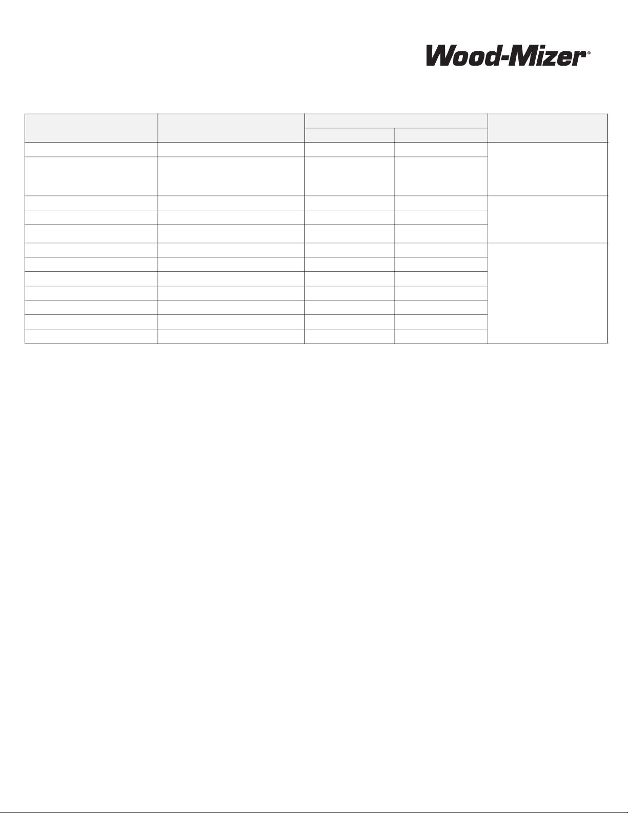
PRODUCT MODEL CLASS LENGTH OF WARRANTY EFFECTIVE DATE
USA & CANADA NON USA & CANADA
Portable Sawmills, Resaws, Edgers LT, LX, HR, EG Two years One year
Date of purchase
Portable Sawmills with Chassis LT28, LT35, LT40, LT50, LT70, LX450
Two years, excluding
the chassis, which chas-
sis shall have a five year
warranty
One year
Industrial Sawmills, Resaws, Edgers WM, HR, EG, TVS, SVS One year One year Date of purchase or date of
installation / training (if applica-
ble), whichever occurs first, not to
exceed 6 months from date of
purchase
TITAN Industrial WB, TV, HR, EG, EA, MR One year One year
Material Handling TWC, IC, TD, LD, GC, CR, CB, CC One year One year
Blade Maintenance Equipment BMS, BMT, BMST One year One year
Date of purchase
Options and Accessories Various One year* One year*
Moulders, Extractors, Kilns MP, MD, KS, KD One year One year
Slab Flattener MB Two years One year
Pallet Equipment PD, PC One year One year
Log Splitters FS One year One year
Replacement Parts Various 90 days 90 days


Introduction
About This Manual 1
Introduction WM doc 4/14/21 1-1
SECTION 1 INTRODUCTION
1.1 About This Manual
This manual replaces any previous information received on your Wood-Mizer® equipment.
The information and instructions in this manual do not amend or extend the limited warranties for the equipment
given at the time of purchase.
1.2 Getting Service
For contact information, sales, service, parts, and additional manuals, sign into your account on https://wood-
mizer.com.

Introduction
Getting Service
1
1-2 WM doc 4/14/21 Introduction

General Safety
Safety Symbols 2
General Safety WM doc 4/14/21 2-1
SECTION 2 GENERAL SAFETY
2.1 Safety Symbols
The following symbols and signal words call your attention to instructions concerning your personal safety. Be sure
to observe and follow these instructions.
DANGER! indicates an imminently hazardous situation which, if not avoided, will result in
serious injury or death.
WARNING! suggests a potentially hazardous situation which, if not avoided, could result
in serious injury or death.
CAUTION! refers to potentially hazardous situations which, if not avoided, may result in
minor or moderate injury or damage to equipment.
NOTICE indicates vital information.
2.2 Safety Instructions
OWNER/OPERATOR'S RESPONSIBILITY
The procedures listed in this manual may not include all ANSI, OSHA, or locally required safety procedures. It is
the owner/operator’s responsibility and not Wood-Mizer LLC to ensure all operators are properly trained
and informed of all safety protocols. Owner/Operators are responsible for following all safety procedures when
operating and performing maintenance to the equipment.
Observe ALL Safety Instructions
NOTICE Read the entire Operator's Manual before operating this equipment.
Note all safety warnings throughout this manual and those posted on the machine.
Be able to access this manual at all times while operating this equipment.
Read additional manufacturer’s manuals and observe their applicable safety instructions.
Only persons who have read and understood the entire operator's manual should operate
this equipment.
This equipment is not intended for use by or around children.
It is the owner/operator's responsibility to comply with all applica-
ble federal, state, and local laws, rules, and regulations regarding
the ownership, operation, and transporting your equipment.
Operators should become thoroughly familiar with and comply with
these applicable laws for operating and transporting equipment.

General Safety
Observe ALL Safety Instructions
2
2-2 WM doc 4/14/21 General Safety

Specifications
Specifications of MD400 and MD500 chip extractors 3
Specifications WM doc 4/14/21 3-1
SECTION 3 SPECIFICATIONS
3.1 Specifications of MD400 and MD500 chip extractors
Wood-Mizer chip extractors nomenclature is given in the table below.
MD400 Overview:.
Chip Extractor Model MD400EA3U MD400EB3U MD500EB5U
Motor Type Electric Motor Electric Motor Electric Motor
Rated Voltage 1x230 V 3x230 V 3x230 V
Mass
Rated power 3 kW 3 kW 5.5 kW
Flow rate 2350 CFM (4000 m3/h) 2350 CFM (4000 m3/h) 2940 CFM (5000 m3/h)
FIG. 3-1

Specifications
Specifications of MD400 and MD500 chip extractors
3
3-2 WM doc 4/14/21 Specifications
MD500 Overview:
When using a collection system, keep in mind:
Check your local waste disposal codes before designing your chip collection sys- tem.
Design access to your chip collection bins so that they can be easily emptied.
Short hose runs and smooth-walled hoses reduce suction loss within the system.
Locate the chip collector near the planer moulder.
Collection systems are loud; use ear protection.
If you are operating this machine in a climate-controlled building and blowing the chips outside, the vacuum
created by the chip collector can quickly empty your building of its heated or cooled air.
If blowing the chips to an indoor bin, an air filter will be necessary to prevent wood dust from reducing the air
quality inside of your building.
If selling chips for use with livestock, do not use harsh chemicals for cleaning or lubricating machinery
FIG. 3-2
Output port
Input port
10" Outlet (537890-US)
2x8" Outlet (310-501)
10" Inlet (537899-US)
5x4" + 1x5" Inlet (310-010-US)
3x4", 1x5" Inlet (537853-US)
TD-MD500-01

Specifications
Overall dimensions 3
Specifications WM doc 4/14/21 3-3
3.2 Overall dimensions
The overall dimensions of both MD400 and MD500 chip extractors and the bagging system are shown below (all
dimensions in foot-inches).
MD 400 Layout
MD500 Layout
FIG. 3-3
FIG. 3-4

Specifications
Overall dimensions
3
3-4 WM doc 4/14/21 Specifications
Bag Collector Assembly Layout
FIG. 3-5

Setup
Attaching the Chip Extractor 4
Setup WM doc 4/14/21 4-1
SECTION 4 SETUP
4.1 Attaching the Chip Extractor
NOTICE Do not use your Chip Extractor if flexible hoses are not attached to it.
All unused ports must be securely blocked off. Do not run your Chip Extractor with open
ports.
The Chip Extractor is attached to external units by means of flexible hoses. The ports fit within the hose, and are
fastened with conventional hose clamps. No special accommodations are required.
4.2 Optional Cyclone Twin Bag Collector Assembly
Tools needed for the assembly are a 6mm hex key and a 13mm open end wrench. A power drill is recommended.
1. Unpack your Cyclone Twin Bag Collector and check that all parts are present:
(2) Collection bags
(2) Bag locks
(3) Legs (no cutouts)
(1) Frame
(14) Short 6mm hex screws
(14) Flat washers
(14) 13mm nuts
(2) Bag bands
(4) Steel rods
(1) Leg (with cutout)
(1) 8” Hose adapter
(6) Long 6mm hex screws
(6) Lock washers
FIG. 4-1

Setup
Optional Cyclone Twin Bag Collector Assembly
4
4-2 WM doc 4/14/21 Setup
2. Attach the hose adapter to the frame with 4 of the long screws with lock washers. Use the lower 4 holes.
3. Position the leg with the cutout on the corner by the hose adapter as shown below:
4. Use short bolts with flat washers and nuts in top two leg holes as shown below:
5. Finish tightening all six long screws with lock washers in the hose adapter and the leg.
FIG. 4-2
FIG. 4-3
FIG. 4-4

Setup
Optional Cyclone Twin Bag Collector Assembly 4
Setup WM doc 4/14/21 4-3
6. Attach the remaining 3 legs with the short screws, flat washers and nuts.
7. Insert the rods into the bag bands as shown below:
8. Place the bag bands with rods into the bags as shown below:
9. Stand the frame and legs upright.
FIG. 4-5
FIG. 4-6

Setup
Optional Cyclone Twin Bag Collector Assembly
4
4-4 WM doc 4/14/21 Setup
10. Place bag locks over the frame openings as shown below:
11. Place the bags over the frame openings by inserting the rods into the mounting holes as shown above:
12. Tuck the bag between the frame openings and the bag locks.
13. Lock the bag locks by closing the latch, as shown below:
14. Install the trash bags under the frame openings.
FIG. 4-7
FIG. 4-8

Setup
Optional Cyclone Twin Bag Collector Assembly 4
Setup WM doc 4/14/21 4-5
15. Swing the square trash bag bracket down by unclipping two latches holding the bracket.
16. Place the trash bag through the bracket as shown below:
NOTE: Ensure that the trash bag full covers the bracket or leakage may occur.
17. Refasten the trash bag clips to seal the trash bag to the frame, as shown below:
18. Attach 8” hose to the inlet port with a standard hose clamp.
Assembly complete.
FIG. 4-9
FIG. 4-10

Operation
General Use
5
5-1 WM doc 4/14/21 Operation
SECTION 5 OPERATION
5.1 General Use
Always be sure that all safety decals are clean and readable. Replace all damaged safety decals to prevent per-
sonal injury or damage to the equipment. Contact your local distributor, or call your Customer Service Representa-
tive to order more decals.
Always properly dispose of all by-products, including debris as wood shavings and dust, coolant and oil.
The chip extractor should only be used for removing sawdust and chips from the processing of wood.
Check your chip extractor as soon as you receive it. Report any transport damage to the transport company imme-
diately.
Spare parts should be sourced through Wood-Mizer.
All electrical installation, service and/or maintenance should be performed by a qualified electrician.
5.2 Site Preparation
WARNING! Have a qualified electrician install the power to your machine. Failure
to follow this may result in serious injury or death.
CAUTION! Improper voltage will cause damage to the motor and electronic components.
Have a qualified electrician install the power supply to the Chip Extractor.
IMPORTANT! The power supply must meet the motor specifications concerning
wire size, fused disconnect, and voltage, which are provided in the motor’s
faceplate. The electrical installation must also meet local codes.
5.3 Extractor Operation
CAUTION! Do not turn on extractor until the unit has been fully assembled. This includes
inlet hoses or caps, as well as outlet hoses and collection systems. Failure to do so may
result in damage to the machine.
1. Secure one end of flex hose to chip extractor inlets with hose clamps. Unused inlet ports must be blocked off. Fail-
ure to do so may result in machine damage and reduced airflow
2. Secure the other end of the flex hose to the unit producing chips.
3. Secure outlet hose to the outlet port with hose clamps. Outlet hose must go to either a chip collection system, chip
container, or vent directly outside.
4. Start motor by pressing the green start button on the control box.
5. On units with multiple outlet ports, while the extractor is off and disconnected from power supply, adjust the inside
baffle of the (optional bagging system) as needed to divert flow equally between the two outlet ports.
5.4 Collection System Operation
CAUTION! Before operation, ensure both the top filter bags and bottom collection bags
are installed and secure. Replace any damaged filters or collection bags.
NOTE: Use only clean or lightly used filters. Dirty filters must be cleaned routinely for opti-
mal airflow.
!
This manual suits for next models
7
Table of contents
Popular Ventilation Hood manuals by other brands

Smeg
Smeg KSET62T Instruction on mounting and use

Schweigen
Schweigen CL8815S installation guide

GUTMANN
GUTMANN SOMBRA EM 68 installation instructions

Miele
Miele DA 424 V EXT Operating and installation instructions

NODOR
NODOR MIRAGE 1425 Manual for the installation, use and maintenance

ROBLIN
ROBLIN Cube 900 Centrale Dimensional drawing