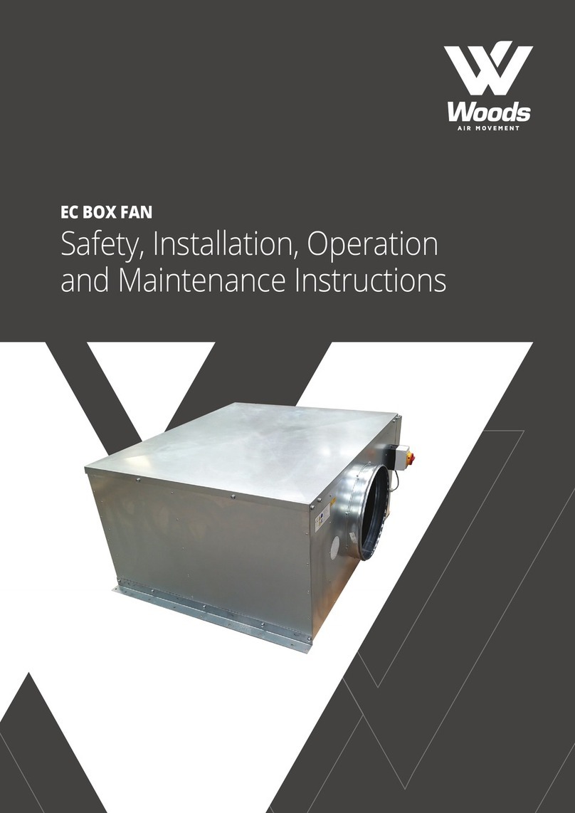
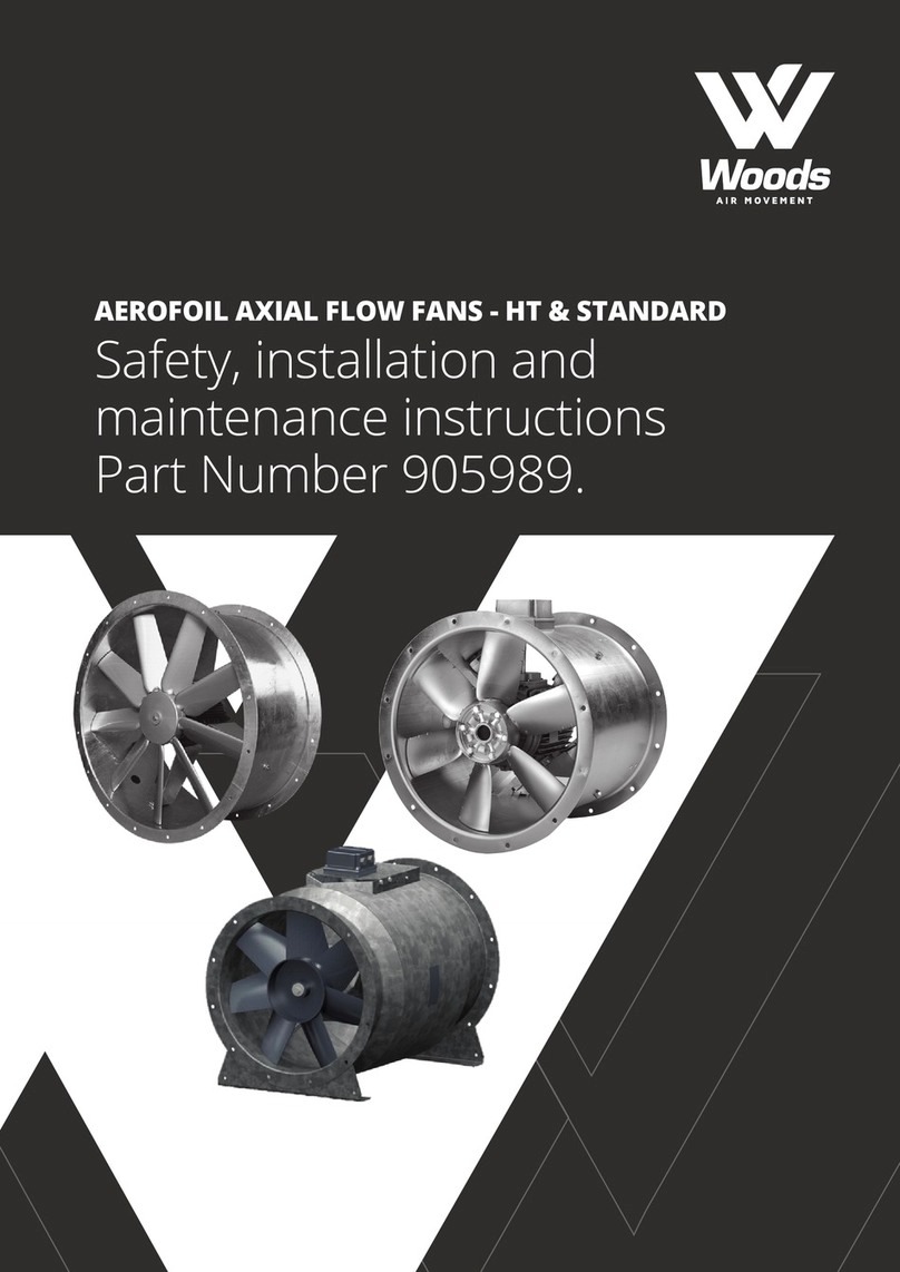
Woods SMHA-031 User manual

SMOKE EXTRACT FAN SMHA HATCH
Installation and
maintenance instructions

CONTENTS PAGE
1. SAFETY NOTES ................................................................................................................................................................................... 3
2. INTRODUCTION & PURPOSE ........................................................................................................................................................ 3
3. SITE STORAGE, SUPPLY, INSTALLATION ................................................................................................................................... 3
4. OPERATING CONDITIONS ............................................................................................................................................................. 4
5. PRODUCT DESCRIPTION ................................................................................................................................................................ 4
5.1 DESIGN ............................................................................................................................................................................................... 3
5.2 SPECIFICATION .................................................................................................................................................................................. 4
5.3 CABLE .................................................................................................................................................................................................. 5
5.4 DIMENSIONS ..................................................................................................................................................................................... 5
6. TRANSPORT ........................................................................................................................................................................................ 6
6.1. TRANSPORT INSPECTION .............................................................................................................................................................. 6
6.2. TRANSPORT SAFETY ....................................................................................................................................................................... 6
6.3. IMMEDIATE STORAGE .................................................................................................................................................................... 6
7. LIFTING ................................................................................................................................................................................................ 7
8. INSTALLATION .................................................................................................................................................................................. 8
8.1. PRODUCT INSTALLATION ............................................................................................................................................................. 8
8.2. SAFETY REGULATIONS .................................................................................................................................................................. 8
8.3. ELECTRICAL CONNECTIONS ....................................................................................................................................................... 9
8.4. WIRING DIAGRAM .......................................................................................................................................................................... 10
9. COMMISSIONING ........................................................................................................................................................................... 11
9.1. PREPARATION ................................................................................................................................................................................ 11
9.2. SAFETY CHECKING ........................................................................................................................................................................ 11
9.3. TEST RUN ........................................................................................................................................................................................ 11
10. MAINTENANCE ............................................................................................................................................................................. 12
10.1. WARRANTY .................................................................................................................................................................................. 12
10.2. MAINTENANCE ........................................................................................................................................................................... 12
10.3. REPLACING THE MOTOR AND IMPELLER ............................................................................................................................. 13
10.4. FINAL INSPECTION ...................................................................................................................................................................... 14
10.5 MECHANICAL OPENING OF THE DOOR .................................................................................................................................. 13
11. FAULTS .............................................................................................................................................................................................. 14
12. SPARE PARTS ................................................................................................................................................................................... 15
13. PRODUCT CODE ............................................................................................................................................................................. 15
14. DECLARATION OF PERFORMANCE .......................................................................................................................................... 16
32
STANDARD VENTILATION FANS
1. SAFETY NOTES
Warning and safety information relevant to specic operations are contained within each section. The following
warning or advice categories are used:
DANGER! Failure to follow these instructions may result in serious injury or death to the user in
addition to serious damage to the equipment.
WARNING! Failure to follow these instructions may result in minor injury or damage to the equipment.
CAUTION! Failure to follow these instructions may result in malfunction or damage to the equipment.
DANGER!
This product contains rotating parts and electrical connections which can be a danger and cause injury.
It is of paramount importance for any fan that is required to function in emergency conditions, that the
installer and user must follow all relevant instructions contained within this leaet which is supplied with
this product. Failure
To ensure that fans will operate continuously during a high air temperature emergency, the electrical system must
have been designed and installed to accommodate the specic emergency conditions of temperature and duration.
A maintenance procedure must be put in place and a record of the activities that have been performed must be kept.
2. INTRODUCTION & PURPOSE
Woods Air Movement SMHA Smoke Exhaust fans comply with the requirements for EN 12101-3 standard and health
and safety of the EC Machinery Directive.
All fans leave the factory after being subjected to testing.
These instructions are intended for use by professional service sta. The installation, commissioning and operation of
the fans must be carried out by professional sta, who are familiar with the safety regulations.
Tools and protective equipment necessary for preventing accidents from occurring while installing and operating the
fan must be used / worn in accordance with the local safety regulations.
All personnel involved with the product must carefully study this operation manual and diligently comply with all notes
and instructions.
Woods does not accept responsibility for any damage that can be attributed to non-compliance of these instructions.
The warranty issued by the manufacturer will be forfeited if any changes to the product are made without the
manufacturer’s consent, please only use approved genuine spare parts.
If ever in doubt, please refer to Woods Air Movement UK (Colchester Oce).
3. SITE STORAGE, SUPPLY, INSTALLATION
WARNING!
When fans are stored (prior to installation), please ensure that access by un-authorised persons is
prevented, by using guards, barriers or secure premises to ensure that fan impellers (which may be
rotating) do not present a hazard.
These instructions relate to all fans rated up to and including 400°C for 2 hours which are designed to be mounted
onto a roof, outside the re zone.

54
4. OPERATING CONDITIONS
Under emergency conditions, these fans are suitable for the temperature/time capability stated on their name plate or in
accompanying documentation. e.g. “HT300/2” or “Ff300 (120)” denotes that a fan is suitable for a single use at an emergency
condition of 300°C for 2 hours (120 minutes). If the emergency air temperature exceeds 400°C, a means of ducting hot
air away from the motor compartment to a safe location must be provided. In addition, a means must also be provided
to force ventilate the motor compartment, in order to supply cooling air which is at less than 40°C. Motor cooling fan and
associated ductwork shall be provided by others.
5. PRODUCT DESCRIPTION
5.1 DESIGN
5.2 SPECIFICATION
The SMHA HATCH product is a mechanical smoke exhaust unit which is designed to be roof mounted. The
equipment is an axial fan with casing designed for the use as an exhaust fan in high temperature emergency
conditions. The product is not designed to be used for normal ventilation.
Our SMHA HATCH product has two JMHT fan temperature variants available: Ff300 (300°C) or F400 (400°C),
both capable of extracting hot smoke for a duration of 120 minutes, as tested and certied in accordance with
EN 12101-3:2015. These product variants are designed for a smoke exhaust duty only. The core range uses IE2
eciency grade motors, but IE3 will be available soon. The hatch and fan are integrated to be one certied unit.
The hatch or lid tted to the top our SMHA unit has been tested to open under a snow load condition of SL 500
(tested in accordance with EN 12101-2). The fan itself should be started 30 seconds after the hatch motors have
been started.
The door is also equipped with a mechanical cable opening mechanism. The mechanism is intended for situations
where it is desired to open the door without electricity.
The standard direction of the smoke exhaust is upwards.
SPECIFICATION OVERVIEW
Product SMHA, Hatch fan
Fan Type HT JM axial fan
Fire Resistance Class Ff300 / F400 for 120 mins
Certifying Body Eurons / BSI
Certicate No 0809-CPR-19001010 / 2797-CPR-474778
Motor eciency Grade Standard: IE2, with IE3 as an option
Between the hatch and casing is sealing material.
Both the hatch and casing have isolation material between metal sheets which makes them thermally insulated.
1. Opening Hatch
2. JMHT fan and re rated motor
3. Safety Mesh
4. Mechanical cable opening opening mechanism
5. Linear motor
6. Limit switch
7. Safety switches
4
5
6
7
1
2
3
5.3 CABLE
Suitable re-resistant cable must be used between the main supply, starter controls and the fan. The mains
supply must be from a guaranteed or separately maintained source, to enable the fan to continue running under
emergency conditions. Duct-mounted terminal boxes for all HT fan specications are designed to accommodate
MICC supply cables.
5.4 DIMENSIONS
E (internal)
G
20
A B 90°
J
K
M
L
D
I
C
F (internal)
H
Diameter
of fan
Fan
Code
Fan
Diameter A B C D E F G H I J K L M
Total
Weight
(KG)*
031 315 1065 1165 1010 315 800 900 980 1080 1245 1135 1935 900 375 192
040 400 1065 1165 1010 400 800 900 980 1080 1245 1135 1935 900 375 192
050 500 1065 1165 1010 500 800 900 980 1080 1245 1135 1935 900 375 230
080 800 1265 1365 1010 800 1000 1100 1180 1280 1445 1335 2135 900 375 353
090 900 1465 1565 1010 900 1200 1300 1380 1480 1645 1535 2335 900 375 389
100 1000 1465 1565 1010 1000 1200 1300 1380 1480 1645 1535 2335 900 375 540
125 1250 1715 1815 1210 1250 1450 1550 1630 1730 1895 1785 2785 1100 575 730
All dimensions are in mm except weight and fan code.
* Complete Weight includes SMHA casing with fan tted (with maximum size fan motor).

76
6. TRANSPORTATION
6.1 TRANSPORT INSPECTION
Check the fan immediately after you receive it and make sure that it has not been damaged during transport.
If you discover any damage, get in touch with the transportation company without delay.
• Check the information on the fan rating plate.
• Proper procedures must be followed when transporting the product.
• Faulty conditions in transporting may result in serious damage on the product.
6.2 TRANSPORT SAFETY
• Loading must be carried out as instructed.
6.3. IMMEDIATE STORAGE
If the fan is to be stored before or in between uses, the following needs to be taken in account:
• Original packaging is to be used.
• If the storage conditions require it, additional protection may be added.
• The hatch of the product must be closed during the storage.
• During long term storage, indoor premises must be used.
7. LIFTING
The SMHA should be lifted to the roof with straps along with a pallet at the bottom of the product. Steel binding
bands used to retain the unit onto its pallet must not be cut before lifting. Lifting strops should be placed under
the pallet so that they are outside the pallet cross/base timbers. Never place strops on the inside of these cross/
base timbers, as this may cause the unit to become unstable and slip.
Once the product has been placed on the roof, on its pallet, the steel retaining bands can be cut. The unit cover
(lid) can then be freely opened, as there isn’t a locking device. The product features lifting lugs, which are only
designed for short transfer lifts from the shipping pallet to the roof surface. Lifting chains can be attached to them.
Keeping the lid open while lifting is ensured
by stringing another chain through the hook
on the inside of the lid.

98
8. INSTALLATION
8.1 PRODUCT INSTALLATION
As with natural ventilation smoke hatch units, our powered SMHA HATCH product can be installed onto a roof
or a car park deck in one lift, as the product is pre-assembled. It can be mounted directly onto a concrete slab or
a similar surface, or onto a specially designed base (builders upstand or suitable metal upstand). Ideally, a at
surface is required for installation.
Integration of the roof structure and the Hatch product, including thermal and water insulation, is carried out in
accordance with the instructions of the structural engineer of the site. If our product is to be used for extracting
smoke from wet rooms, measures must be taken to prevent build-up of condensation. If the unit needs to draw
in air freely from the space below, the product should be equipped with an inlet safety guard. In this case, the
product can be mounted directly onto a at surface. If the fan is to be connected to ductwork, it can be delivered
with an inlet counter ange to facilitate easy connection to ductwork.
Fig. 1 Fig. 2
16
7
5
9
3
4
2
8
1. Opening hatch
2. JMHT fan
3. Impeller
4. Motor
5. Safety guard / counter ange
6. Hatch motors, 2 pcs.
7. Safety guard on the outlet
8. Roof structure
9. Roof Installment Options - see gure 1 and 2.
10. Fan safety switch
11. Safety switch for hatch motors
12. Limit switch
Angle brackets should be xed to the unit’s base with a minimum
of four 5x40 screws or to the roof structure with a minimum of
four screws as follows:
- 4 to 6 HILTI HPS-1 screws 6/5x30 for concrete
- 4 to 6 wood screws 5x50 for wood
- 4 to 6 self-drilling screws 5.5x25 for steel-reinforced concrete
1
7
5
9
8
2
6
4
3
Figure 1
Attachment to the roof
directly by the unit’s
anged base
Figure 2
Attachment to the roof
structure with angle
brackets
8.2. SAFETY REGULATIONS
DANGER! Where the unit hatch is open for maintenance work, there is a risk of falling through the fan
opening, especially where the fan has been removed from the product. Special care should
be taken to prevent falling during the maintenance work.
8.3. ELECTRICAL CONNECTIONS
WARNING! All electrical connections must be wired by authorised personnel only.
The necessary electrical and safety precautions in this instruction manual must be followed.
The unit is equipped with 2 safety electrical isolator switches, one for the fan motor and one for the opening
motors. The product is equipped with a limit switch, which provides information on the opening or closing of the
hatch. Electrical connections as shown in the diagram below (see diagram under heading 8.4 Wiring Diagram).
The cable connection from fan terminal box to the fan motor must be made using a re-resistant cable. Cable
entries in the casing must be sealed with reproof sealant.
It is advisable to only use the hatch limit switch to provide a signal as an indication that the “hatch is closed”
(for information only). A motor start signal should be provided by a separate control circuit. To ensure correct
operation, the control logic must ensure that the fan starts at least 30 seconds after the linear actuator motors
(which open the hatch or lid) have been energised.
WARNING! Linear motors must not be exposed to the control voltage!
NOTE! The approximate hatch closing time is 3 minutes, after which the
power must be turned o.
Safety switch
Viewed from the hinged side of the hatch, the safety
switches are on the right-hand side of the casing.
Safety Switch

1110
Limit switch
Installed on site
Factory installation
Linear motor Linear motor
Smoke extract
fan motor
Safety switchSafety switch
Max 3 min run time
Black (L-OPEN)
Blue (N)
Yellow (DATA A)
Green (DATA B)
Brown (L-CLOSED)
The cable connection from fan terminal box to the fan motor must be
made using a re resistant cable. Cable entries in the casing must be
sealed with reproof sealant.
It is advisable to only use the hatch limit switch to provide a signal as an
indication that the “hatch is closed” (for information only). A motor start
signal should be provide by a separate control circuit. To ensure correct
operation, the control logic must ensure that the fan starts at least 30
seconds after the linear actuator motors (which open the hatch or lid)
have been energised.
NOTE!
The approximate hatch closing time
is 3 minutes, after which the power
must be turned o.
8.4. WIRING DIAGRAM 9. COMMISSIONING
9.1. PREPARATION
Open the hatch and connect the motor rods to the fastenings. Connect the mains to the motors to close the hatch
NOTE! Make sure that it is also possible to open the hatch after using a
temporary power supply (eg disconnect linear motor shafts after
test run).
9.2. SAFETY CHECKING
Make sure that the fan motor and hatch motors are disconnected from the mains. Rotate the shaft and check that
the impeller can move freely. Make sure that there are no foreign objects in the fan or in the ducting. Also check
that there is no unusual noise in the fan. Check that the installation work has been carried out in accordance with
the relevant regulations. All necessary protective devices must be installed.
Check also, that the unit design airow is being met. Ensure that all other regulations related to re safety are
followed.
The fan may only be commissioned after all proper procedures have been followed and all necessary inspections
have been carried out.
9.3. TEST RUN
Briey switch on the power supply to the motor to check whether the fan impeller rotates in the correct direction.
Operate the fan for at least 30 minutes. If the impeller is rotating in the correct direction shown with the arrow, the
fan may be switched on. Check that no abnormal mechanical sound and no performance surging occurs, if so, turn
it o immediately.
NOTE! During the test run, please ensure that the fan has an adequate supply of replacement air.
During the installation process, it is important to check that the air velocity (across the hatch opening) does
not exceed 10 m/s. If the air velocity does exceed this value, this could result in damage to the door hinge and
actuation mechanisms.

1312
10. MAINTENANCE
10.1 WARRANTY
A precondition of the warranty is that regular maintenance has been carried out. Defects under warranty must
immediately be notied to the manufacturer or the importer. The warranty does not cover service work or indirect
damages.
10.2 MAINTENANCE
10.2.1 BEFORE MAINTENANCE
Switch o the power supply to the fan and hatch actuator motors at the safety isolating switches. Note: the hatch
(lid) stays open when the unit isolator switches are used to disconnect it from the mains electrical supply. However,
make sure that hatch cannot fall and close during maintenance.
10.2.2 INSPECTION INTERVALS
Inspection intervals can be dened by local authorities. If this is not dened, the fan must be tested according to
the intervals in table below, at least once a year. The annual inspection must be done by authorised personnel
only. Also follow the separate JMHT fan operation manual instructions for maintenance on the fan inside the
casing.
Pos Description Introduction 6 months 12 months
1Check that the hatch opens properly and the supply of
replacement air is ensured. x x x
2Check that the fan motor starts 30s after the hatch
opening motors x x x
3Check that the hatch motor is de-energised after
3 min. start-up x
4Check that the fan rotates properly
(and in the right direction) x x x
5Check that all warning/alarm lights are OK x x
6Check that all labels are correct and visible x x
7Visual inspection of fan motor and hatch opening motors x x
8Test run of the fan x x
9The entire product has been inspected for damage x x x
10 Make an inspection report x
11 Make a maintenance report x x
Fan motor
1During the test run, check the bearings for abnormal noise x
2If needed, lubricate the bearings x
3Check that the impeller rotates properly x
4Perform a visual inspection. x x
10.2.3. CHECKING THE MOTOR BEARINGS
The fan motor should be operated during test runs, maintenance or in emergency conditions only. The motor
bearings need to be lubricated and serviced in accordance with the instructions that accompany the motor.
As motors are designed for use in a Fire Safety product, they should not be repaired by local repair Engineers.
The complete motor or fan/motor unit should be replaced.
10.2.4. IMPELLER
CAUTION! The impeller must be clean.
10.3. REPLACING THE MOTOR AND IMPELLER
The fan will have to be disconnected from the unit before the motor can be replaced.
SMHA-031,040,050,080,090
1. Check that the fan motor and hatch motors are disconnected from the mains.
2. Remove outlet safety guard.
3. Remove the impeller from the motor shaft by loosening the locking screws from the shaft end.
4. Remove the hub from the shaft. Please take care and ensure it does not fall through the casing.
5. The motor rotor can be lifted so that the bearings can be checked or replaced.
SMHA-sizes 100-125
1. Check that the fan motor and hatch motors are disconnected from the mains.
2. Remove outlet safety guard.
3. Remove the complete fan and lift it outside the casing for maintenance.
4. Follow the maintenance instructions for the JMHT fan.

1514
10.4 FINAL INSPECTION
Check that:
• The impeller is mounted for the correct direction of rotation.
• All screws and nuts have been tightened to the corrrect torque values.
• No foreign objects have been left in the casing or in the ducting.
• The mechanical opening of the hatch works.
10.5 MECHANICAL OPENING OF THE DOOR
The mechanical opening of the hatch is intended for emergency situations where the door has to be opened when
the electrical supply has been disrupted/turned o.
The door can be opened mechanically by pulling the wires under the hatch. There are two wires, and they are
located on both sides of the linear motors. Pulling on the wire requires some force, so you must use an aid, such as
a steel rod, formed into a hook (see picture for example).
After mechanically opening the lid, re-attach the linear motor shafts to the mounting lugs and make sure that the
cover seals are intact.
11. FAULTS
If any faults occur during inspection which cannot be repaired by maintenance personnel, please contact the
service department at Woods Air Movement.
Examples of faults can include the following issues:
• Foreign bodies inside the fan
• Corroded items (xings etc.) which are located inside the casing
• High vibrations
• Maintenance negligent
• Hatch not opening
Possible problems generated:
• Bearing damage
• Corrosion damage
• Excessive vibration generated damage
12. SPARE PARTS
Only use genuine spare parts supplied and accepted by Woods Air Movement. If any other spare parts are used,
then the warranty and EN-certication are no longer valid.
Spare parts:
• Fan motor
• Hatch motor
• Impeller
• Safety switches
13. PRODUCT CODE
Smoke extract fan SMHA – AAA – BBB – CD – EF – PA
Fan Size
031, 040, 050, 080, 090,100, 125
Motor rating
048 = 4.8 kW.,etc.
C – Product Version
1 = Current version
D – Installation Accessories #1
E - Hatch casing colour / nish #2
F - High Temperature Category #3
PA – Fan pitch angle
NOTES:
Note #1 INSTALLATION ACCESSORIES (on fan inlet)
1 = Safety mesh (at guard)
2 = Matching Flange
Note #2 HATCH CASING COLOUR / FINISH Options
1 = Galvanised
2 = Tele Grey 1 RAL 7045
3 = Window Grey RAL 7040
4 = Graphite Grey RAL 7024
5 = Jet Black RAL 9005
6 = White Aluminium RAL 9006
7 = Special Colour
Note #3 HIGH TEMPERATURE CATEGORY Options
3 = Ff300 (300°C/2 hours)
4 = F400 (400°C/2 hours)

1716
14. DECLARATION OF PERFORMANCE
FG_DC_10750GB_SMHA_F300_DOP_20220930_R0
DECLARATION OF PERFORMANCE
No. 022CPR2022-09-30
1. Unique identification code of the product-type:
Powered smoke and heat exhaust ventilator SMHA with accessories
2. Type, batch or serial number or any other element allowing identification of the construction product as required
under Article 11(4):
Powered smoke and heat exhaust ventilator SMHA F300, Ff300 (120)
3. Intended use or uses of the construction product, in accordance with the applicable harmonised technical
specification, as foreseen by the manufacturer:
Powered smoke and heat exhaust ventilator
4. Name, registered trade name or registered trademark and contact address of the manufacturer as required
pursuant Article 11(5):
FläktGroup Finland Oy, Rydönnotko 1, 20360 Turku, Finland
5. System or systems of assessment and verification of constancy of performance of the construction product as set
out in Annex V:
System 1
6. Eurofins Expert Services Oy, Finland, Nr. 0809
Performed determination the product type on the basis of type testing; initial inspection of the manufacturing
plant and of factory production control; continuous surveillance, assessment and evaluation of the factory
production control (FPC) under system 1and issued: Certificate of constancy of performance 0809-CPR-
19001010.
7. Declared performance:
8. The performance of the product identified in points 1 and 2 is in conformity with the declared performance in point
7. This declaration of performance is issued under the sole responsibility of the manufacturer identified in point 4.
Signed for and on behalf of FläktGroup by:
Jari Hokkanen, R&D Manager Turku 30.09.2022
…………………………………………...........
Essential characteristics
Harmonized
technical
specification
Response delay:
- opening under wind load
- opening under snow load
Sizes 031 - 100 / Size 125
Operational reliability:
- Application categories
- Motor rating
Effectiveness of smoke / hot gas extraction
Gas flow and pressure maintenance during
smoke and heat extraction test
Resistance to fire:
Ability to open under environmental conditions:
- Opening under wind load
- Opening under snow load
Sizes 031 - 100 / Size 125
Durability of operational reliability
Performance
≤ 30 s
SL 1250 / SL 800
EN 12101-3:2015
Smoke extraction
Class H / Class F
-10 % ≤ Flow ≤ +25 %
F
300
, F
f300
(120)
≤ 30 s
SL 1250 / SL 800
Class H / 105K
FG_DC_10700GB_SMHA_F400_DOP_20220930_R1
DECLARATION OF PERFORMANCE
No. 019CPR2022-09-30
1. Unique identification code of the product-type:
Powered smoke and heat exhaust ventilator SMHA with accessories
2. Type, batch or serial number or any other element allowing identification of the construction product as required
under Article 11(4):
Powered smoke and heat exhaust ventilator SMHA F400 (120)
3. Intended use or uses of the construction product, in accordance with the applicable harmonised technical
specification, as foreseen by the manufacturer:
Powered smoke and heat exhaust ventilator
4. Name, registered trade name or registered trademark and contact address of the manufacturer as required
pursuant Article 11(5):
FläktGroup Finland Oy, Rydönnotko 1, 20360 Turku, Finland
5. System or systems of assessment and verification of constancy of performance of the construction product as set
out in Annex V:
System 1
6. Eurofins Expert Services Oy, Finland, Nr. 0809
Performed determination the product type on the basis of type testing; initial inspection of the manufacturing
plant and of factory production control; continuous surveillance, assessment and evaluation of the factory
production control (FPC) under system 1and issued: Certificate of constancy of performance 0809-CPR-
19001010.
7. Declared performance:
8. The performance of the product identified in points 1 and 2 is in conformity with the declared performance in point
7. This declaration of performance is issued under the sole responsibility of the manufacturer identified in point 4.
Signed for and on behalf of FläktGroup by:
Jari Hokkanen, R&D Manager Turku 30.09.2022
…………………………………………...........
Essential characteristics
Harmonized
technical
specification
Response delay:
- opening under wind load
- opening under snow load
Sizes 031 - 100 / Size 125
Operational reliability:
- Application categories
- Motor rating
Effectiveness of smoke / hot gas extraction
Gas flow and pressure maintenance during
smoke and heat extraction test
Resistance to fire:
Ability to open under environmental conditions:
- Opening under wind load
- Opening under snow load
Sizes 031 - 100 / Size 125
Durability of operational reliability
Performance
≤ 30 s
SL 1250 / SL 800
EN 12101-3:2015
Smoke extraction
Class H / Class F
-10 % ≤ Flow ≤ +25 %
F
400
(120)
≤ 30 s
SL 1250 / SL 800
Class H / 105K

Woods Air Movement delivers smart and energy
efficient Air Movement and Fire Safety solutions to
support every application area. We offer our customers
innovative technologies, high quality and outstanding
performance. The widest range of Air Movement and
Ventilation products in the market, and strong market
presence with over 100 years of experience and
manufacturing of products, guarantees that we are
always by your side, ready to deliver Excellence in
Solutions.
Contact our friendly sales team today
for more information
Call: +44 (0) 1206 222 555
Email: [email protected]
www.woodsairmovement.com
WAM_DC_00046GB_Standard Roof Fans_OM_20210927_R0_.pdf
This manual suits for next models
4
Table of contents
Other Woods Fan manuals
Popular Fan manuals by other brands

Progress Lighting
Progress Lighting AirPro P2540 installation manual

climacity
climacity PUR LINE VENTY WA 55 user manual

BLAUBERG Ventilatoren
BLAUBERG Ventilatoren ISO-RB Series user manual

Panasonic
Panasonic FY-E15PM1 operation instruction

ebm-paps
ebm-paps K3G560-PB31-03 operating instructions

Sunforce
Sunforce SOLAR VENT 1000 user manual

NuTone
NuTone 754RBNT instructions

Carrier
Carrier FX4D series installation instructions

Clarke
Clarke Air CBF20 Operation & maintenance instructions

Brink
Brink Air Comfort Installation regulations

Hunter
Hunter 21101 Manual de Installatión y Operatión

Vallox
Vallox 252 D Series Instructions for use and maintenance