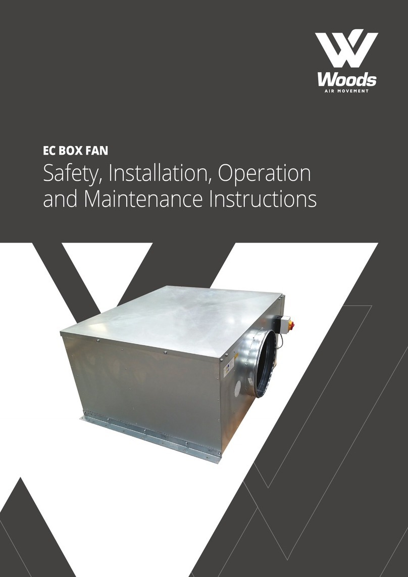
Woods EC BOX FAN Instruction Manual

WOODS EC TWIN AND SINGLE BOX FANS (1PH)
Safety, Installation and
Maintenance Instructions

1. INTRODUCTION
Designed for internal applications, the Woods EC Twin & Single box fan range encompasses models of direct driven
centrifugal fan units with airow duties up to 3.5m3/s. Not suitable for outdoor applications.
Motor windings are tted with an auto-reset thermal cut-out.
Motors are pre-wired to an external terminal box speed controller, auto-changeover & isolator.
2. GENERAL CONSTRUCTION
Casework is manufactured from 0.9mm to 1.2mm thick galvanised sheet steel with an ‘O’ class foam / barrier mat
insulation to provide acoustic insulation. Access is via a removable top cover. Fitted backdraught shutters prevent
recirculation via inoperative fan.
Discharge via optional bird-mesh protected cowl.
3. INSPECTION UPON RECEIPT OF GOODS
Immediately upon receipt of any goods, a careful inspection should be undertaken to ensure neither damage has
occurred nor parts missing.
Particular attention should be paid to the fan impeller, motor shaft, anti-vibration mounts, exible connection, coil
connection & casework.
In the event of such damage or loss having occurred, inform supplier WITHIN 3 WORKING DAYS of the delivery
date, giving the serial number which can be found on the nameplate. After this period we will be unable to
entertain any claim for loss or damage.
4. HANDLING
Units being craned into position must be handled with care to avoid damage.
5. INSTALLATION
When installing our equipment, the following instructions below must be observed.
6. SAFETY
It is the responsibility of the installer to ensure that the installation complies with the legal regulations and the
current HEALTH AND SAFETY AT WORK ACT.
7. AMBIENT TEMPERATURES
The range of units covered by this manual are designed for use in an environment where the ambient air
temperature is unlikely to exceed 50oC.
8. MOUNTING
These units must be mounted in the horizontal plane. Bottom access can be accommodated if advised at time
of order. These fans are not suitable for inverted mounting on to the ceiling.
CONTENTS PAGE
1. INTRODUCTION ............................................................................................................................................................ 3
2. GENERAL CONSTRUCTION .......................................................................................................................................... 3
3. INSPECTION UPON RECEIPT OF GOODS ................................................................................................................... 3
4. HANDLING ..................................................................................................................................................................... 3
5. INSTALLATION .............................................................................................................................................................. 3
6. SAFETY ........................................................................................................................................................................... 3
7. AMBIENT TEMPERATURES .......................................................................................................................................... 3
8. MOUNTING ................................................................................................................................................................... 3
9. POSITIONING ................................................................................................................................................................ 4
10. DUCT CONNECTIONS ................................................................................................................................................... 4
11. ACCESS ........................................................................................................................................................................... 4
12. ELECTRICAL WIRING ..................................................................................................................................................... 4
13. MAINTENANCE .............................................................................................................................................................. 4
14. FAN WIRING ................................................................................................................................................................... 5
15. CONTROLS FUNCTIONALITY ....................................................................................................................................... 6
16. GENERAL DESCRIPTION ............................................................................................................................................... 6
17. INSTALLATION .............................................................................................................................................................. 6
18. OPERATION ................................................................................................................................................................... 6
18.1 DIAGNOSTIC ........................................................................................................................................................... 6
18.2 RUN MODES ........................................................................................................................................................... 7
18.3 FAN SPEED CONTROL ............................................................................................................................................ 7
18.4 BMS ......................................................................................................................................................................... 7
19. LED’S ............................................................................................................................................................................... 7
20. TEST MODE .................................................................................................................................................................... 7
21. DECLARATION CERTIFICATE ....................................................................................................................................... 8
32

9. POSITIONING
All units should be mounted on a completely at base.
Mounting brackets are provided with the units.
10. DUCT CONNECTIONS
Adjoining ductwork should always be independently supported to avoid undue stress on the unit casing. Impellers
are statically and dynamically balanced, anti-vibration mounts and fast clamps are available to suit.
11. ACCESS
All units are designed with easily removable components for maintenance purposes. Sucient room should be
kept to allow components to be withdrawn.
12. ELECTRICAL WIRING
Electrical supply must be fully isolated before attempting to aect any work on the unit.
All wiring should be carried out by a competent electrician and should comply fully with the current I.E.E. Wiring
regulations.
The electrical supply must be as stated on the nameplate.
When the wiring is complete, check for free & correct rotation of the fan impeller.
13. MAINTENANCE
HALF YEARLY
The fan impeller should be carefully cleaned with a brush. This will prevent the impeller from becoming unduly
dirty and become unbalanced.
ANNUAL
The security and integrity of all fastenings should be checked. Particular attention should be paid to the impeller
xing onto the fan shaft
54
14. FAN WIRING

76
18.2 RUN MODES
• The controller is intended to operate the unit as duty-share auto-changeover - NORM
o Duty-share time period (1-12 hours) is dened by pot - C/O TIME
o Auto-changeover activated upon failure of running fan
• Either fan can be forced to run continually, bypassing the duty-share & auto changeover operations, if required –
OVERIDE
• Both fans can be forced to run continually, bypassing duty-share auto changeover operation, in duplex mode if
required - OVERIDE
18.3 FAN SPEED CONTROL
TRICKLE V – Trickle speed 0% - 100%
BOOST V – Boost speed 0% - 100%
RUN ON TIME – Boost run-on time 0 – 20 minutes
18.4 BMS
• VFC Enable – shipped linked
• VFC Boost – Fan will run at Trickle set-point until the link is closed. Fan will continue to run at Boost set-point
as long as the link is closed or for the duration of the run-on time. Boost LED remains solidly illuminated when
activated, and ashes during run-on period.
• Remote Speed – A 0-10V signal can remotely vary the fan speed between the Trickle & Boost set-points as
minimum and maximum limits
• Fault Relay – To prevent false positives, a continual fault of 30 seconds is required before a fault condition is
reported. Upon a fault condition the relevant fan LED will ash and relay will switch to fault condition. Faults are
reset upon a power cycle. Relay rated for 12A / 250Vac
19. LED’S
POWER – Solid illumination when controller has power applied
FAN1 – Solid illumination when active, ashing when in fault
FAN2 – Solid illumination when active, ashing when in fault
BOOST - Solid illumination when active, ashing when in run-on period
20. TEST MODE
All unit are test run before dispatch to conrm correct operation of the above functions.
There is a factory test mode to aid troubleshooting. Contact us if assistance is required with troubleshooting.
15. CONTROLS FUNCTIONALITY
Suitable for single phase fan motors, for a 230V 50Hz single phase mains supply
16. GENERAL DESCRIPTION
• IP65 rated enclosure
• Fascia isolator
• Individual fan motor fuses
o MCB for 3 phase fan motors
• Illuminated Indication
o Panel live indicator
o Fan run indicator
o Fan fault indicator
o Boost indicator
• Customer connections
o VFC BMS enable
o VFC BMS boost
o Fan fault BMS link
o Remote 0-10V speed control
17. INSTALLATION
The controller is supplied tted to the unit, pre-wired to fan motors and mains isolator and is suitable for internally
& externally mounted units.
The enclosure is opened with a at-head screwdriver to release the hinge, and 2 Philips head screws beneath the
open hinge.
18. OPERATION
18.1 DIAGNOSTIC (FOR TWIN FAN)
• On initial power-up the fault relay will be energized into the normal “No Fault” condition.
• Fan 2 will run for 30 seconds to allow the control to monitor the correct running of the fan.
• If no fan fault is detected the control will switch from Fan 2 to Fan 1
• If Fan 2 is found to be faulty the control will go into fault mode and Fan 1 will run

8
21. DECLARATION CERTIFICATE
Declaration of Conformity - CE
As defined by the EC Machinery Directive 2006/42/EC
Manufacturer Woods Air Movement
Axial Way
Colchester CO4 5ZD, GB
Herewith we declare that the machine:
Designation of the machine Model or Type of machine Since year of manufacture
Woods EC Box fan (Single & Twin) EC Box fan 2021
Meets the basic requirements of the guidelines:
•ISO 9001-2015
•ISO 14001-2015
•QMS Cert No: 374622021
The following harmonized standards are applied:
EN 60204-1: 2018 EN ISO 12100:2010 EN ISO 13857:2008 EN 61000-3-2:2014
EN 60950-1:2006 EN 61000-3-3:2013
The specific technical documentation in accordance with Appendix VII B has been written and is available in its
entirety. The specific documentation will be transmitted to the official authorities on justified request through
electronic means, on data carriers or on paper.
Name of the representative for documentation:
Address of the nominated person: see manufacturers address
EC-Declaration of Conformity was issued:
Colchester, 31-Aug-22
Place, Date Simon Chapman
R&D Director Woods Air Movement
9

Woods Air Movement delivers smart and energy
efficient Air Movement and Fire Safety solutions to
support every application area. We offer our customers
innovative technologies, high quality and outstanding
performance supported by more than fifty years of
accumulated industry application experience.
The widest range of Air Movement and Ventilation
products in the market, and strong market presence
with over 100 years of experience and manufacturing
of products, guarantees that we are always by your
side, ready to deliver Excellence in Solutions.
Contact our friendly sales team today
for more information
Call: +44 (0) 1206 222 555
Email: [email protected]
www.woodsairmovement.com
WAM_DC_00053GB_EC Box Fan 1Ph_OM_2021104_R0_.pdf
Other manuals for EC BOX FAN
1
Table of contents
Other Woods Fan manuals
Popular Fan manuals by other brands

Pro-Elec
Pro-Elec PEL00305 instruction manual

Mylek
Mylek MY146 User instructions

S&P
S&P HTB-75 RC Installation manual and operating instructions

KDK
KDK 20AUH Service manual

Town & Country Fireplaces
Town & Country Fireplaces TCVT.SSWTA Installation and operating instructions

Field Controls
Field Controls AB-1 Specifications

AirTechnic
AirTechnic AIR-10S user manual

Greenheck
Greenheck XG-FCI Installation, operation and maintenance manual

Hinkley
Hinkley 60" Hover instruction manual

Vent-Axia
Vent-Axia eMF Series Installation and wiring instructions

UFESA
UFESA SF1410 alize instruction manual

Soleus Air
Soleus Air AIR301HF W quick start guide