Woody Valley Crest User manual


CREST - User Manual
2
ENG
Congratulations on your purchase of a WOODY VALLEY product.
We would like to remind you that all our products are the result of
meticulous research in constant collaboration with pilots from all
over the world. That’s why your opinion is so important to us. Your
experience and collaboration help us constantly improve our har-
nesses, to always get the best out of every Woody Valley creation.

CREST - User Manual
3
ENG
MANUFACTURER INFORMATION:
WOODY VALLEY s.r.l.
via Linz, 23 - 38121 Trento - ITALY
Tel +39 0461 950811 - Fax +39 0461 950819
Web: www.woodyvalley.eu
E-mail: [email protected]
DATA CONTAINED ON THE
HARNESS LABELS
Manufacturer infor-
mation
Harness name
Approved load
Production
batch
Size
Approval
code
Barcode
Serial number
Reference standard
for harness certica-
tion
Dealer-distributor
information
Date of sale of the
harness

CREST - User Manual
4
ENG
THANK YOU
We would like to thank you for choosing a Woody Valley product. We invite
you to please carefully read this important document, the harness user
manual and to take special account of the two most important paragraphs
concerning:
INSERTING THE RESERVE PARACHUTE
The reserve parachute is a life-saving piece of equipment. It must be insert-
ed so that it works correctly when required, whether this happens in two
days’ time or two years from now.
ADJUSTING THE HARNESS
The harness is the connecting point between the pilot and the paraglid-
er and it is a necessary component for optimising ight performance and
pleasure. A bad harness that is well adjusted may enable you to y well, but
a good harness that is incorrectly adjusted may put you off ying altogeth-
er.
We are condent that this harness will give you great comfort, control, per-
formance and enjoyment in ight. We are well aware that reading a user
manual may not be the most exciting thing to do. However, please remem-
ber that this product is not a simple citrus juicer or a mobile phone and that
correct use of the harness helps reduce the risk of ying accidents. This
manual contains all the information necessary to assemble, adjust, y and
store your harness. Thorough knowledge of your equipment will improve
your personal safety and your ying potential.
The Woody Valley Team
SAFETY NOTE
By purchasing Woody Valley equipment, you are responsible for being a
certied paraglider pilot and you accept all risks inherent with paragliding
activities including injury and death. Improper use or misuse of equipment
greatly increases these risks. In no case shall Woody Valley or Woody Val-
ley equipment resellers be held liable for personal or third party injuries or
damages under any circumstances. If any aspect of the use of our equip-
ment remains unclear, please contact your local reseller or Woody Valley
directly.

CREST - User Manual
5
ENG
CONTENTS
1- GENERAL INFORMATION
1.1 - Concept
1.2 - Protection and safety
1.3 - S.O.S label
1.4- RECCO system
2 - BEFORE USING
2.1 - Reserve parachute
2.1.1 - Refolding the reserve parachute in the deployment bag
2.1.2 - Connecting the reserve parachute to the harness
2.1.3 - Inserting the reserve parachute
2.1.4 - Compatible reserve parachutes
2.1.5 - Extracting the reserve parachute
2.2- Harness adjustments
2.2.1 - Back adjustment
2.2.2 - Shoulder-pad adjustment
2.2.3 - Chest strap adjustment
2.2.4 - Seat height adjustment
3- FLYING WITH CREST
3.1 - Preight checks
3.2 - Pockets
3.3 - Camel-bak
3.4 - Tandem ying
3.5 - Flying over water
3.6 - Winch launch bridle attachment
3.7 - Landing with CREST
3.8 - Disposing of the harness
3.9 - Regulations for behaviour in natural environments
4 - REFOLDING THE HARNESS
stowing the glider and using the rucksack
5 - CHARACTERISTICS AND INSTALLATION OF THE SPEED SYSTEM
6 - MAINTENANCE AND REPAIR
7 - WARRANTY
8 - APPROVAL CERTIFICATES
9 - TECHNICAL DATA

CREST - User Manual
6
ENG
1- GENERAL INFORMATION
This manual is an integral part of the CREST harness and should be stored
in a safe place for future reference.
For further information, please contact your dealer or Woody Valley direct-
ly.
The pilot is advised to read this manual carefully before using the harness.
Declaration of conformity
The manufacturer WOODY VALLEY Srl hereby declares that its products
comply with standard UNI EN 1651- LTF 91-09
This equipment must contain:
- Harness
- Snap-hooks
- Dedicated emergency container with attached handle
- 2 reserve elastic loops for closing the reserve parachute
- Two step light speed-bar
- “V” bridle (red and white)
- Rucksack
The main options available are:
- Concertina light
- Radio poket
Back
adjustment
Snap-hooks
Chest strap
adjustment
Should strap
fastener
Shoulder
strap
adjustment
Leg strap
closing loop

CREST - User Manual
7
ENG
1.1- Concept
CREST is designed to be used as a harness for sport paraglider ying with a
maximum weight of 120 kg.
CREST is designed for placement in the Hike & Fly category. In less than 2 kg,
we have created a revolutionary reversible harness with high performance
airbag thanks to the use of new construction materials and systems.
The innovative geometry of the strap system and the GET UP safe leg strap
closing system has been designed for easy donning of the harness and for
precise, smooth handling, in addition to being extremely lightweight.
The original reversibility system makes it possible to totally detach the
rucksack from the harness, depending on user preference.
Painstakingly designed in every detail, CREST offers excellent in-ight com-
fort and can be adapted to novice or experienced pilots by adjusting the
length of the chest strap.
1.2- Protection and safety
CREST uses a shape-retaining airbag, plus it has a new frontal air inlet that
ensures good ination.
Thanks to the use of Nitinol (highly resistant and super elastic metallic wire)
inserted in the lower edge of the airbag, the CREST airbag is able to obtain
60% of the protective capacity before complete ination which takes place
in ight. The ination valve has also been completely redesigned to guaran-
tee airow in the airbag regardless of leg position. The new valve improves
airbag performance and aesthetics.

CREST - User Manual
8
ENG
Harness Impact Pad Report
Inspection certificate number: PH_347.2021
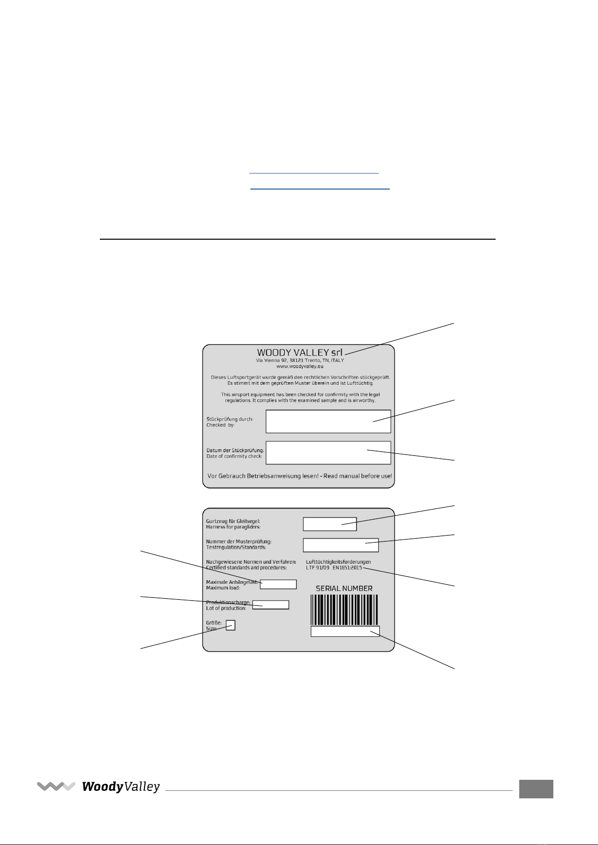
Manufacturer data: Sample data:
Manufacturer name: WoodyValley srl Name impact pad: n/a
Representative: Simone Caldana Impact pad intgrated: Yes
Street: Via Vienna 92 Impact pad type: Airbag
Post code place: 30121 Trento Weight of sample [kg]: n/a
Country: Italy Serial number: n/a
Date of test: 27.09.2021
Harness model: Crest M
Atmosphere AGL:
Temp.
[C°]
22
R.H. [%] 54
Press. [hPa]
1008
Summary of Impact pad test (1)
Test id
_
Max Peak of
Impact [g]
(3)
Duration at 38 [g]
in [ms]
(4)
Duration at 20
[g] in [ms]
(5)
Diff. of test 1
and 2 [%]
(6)
Result
PV
19.79 0.00 0.00 17.59 POSITIVE
PR V19.23 0.00 0.00 6.34 POSITIVE
Manufacturer Instrument Type no S/N
Burster/MTS Accelerometer 100 g 89010-100 1263567
JDC elec Geos n°11 Skywatch Geos n°11 Unit11
This declaration must not be reproduced in part without the written permission of AIR TURQUOISE SA.
The validation of this test report is given by the signature of the test manager on the Inspection Certificate no 94.20
Test sample attached to dummy in flying
position, without emergency parachute
Test sample attached to dummy in flying
position, Including emergency parachute
Test configuration
(2)
(1) Calculated values in tests reports include the value minus the uncertainty (on safe side) / The uncertainty stated is the expanded uncertainty obtained by multiplying the standard
uncertainty by the coverage factor k = 2. The value of the measurand lies within the assigned range of values with a probability of 95%.
(3) Maximum peak of impact should be less or equal to 50 [g], (4) If any, the maximum duration in at 38 [g] should be less or equal to 7 [ms], (5) If any, the maximum duration in at 20 [g]
should be less or equal to 25 [ms].
(6)
The test should be done twice, and the 2nd test the maximum peak should not differe more than 20% from the first test, maximum peak.
(2) The dummy is lifted minimum up to 1.65 m, and impact pad is mounted on. Where the impact occurs, measure distance from bottom of impact pad to ground.
Validity Calibration
23.01.2024
18.06.2025
Air Turquoise SA
, having thoroughly assessed the sample mentioned above, declares it was found conform with all requirements defined by the following norms:
Airworthiness Requirements NfL 2-565-20 - European Standard EN1651 :2018
Rev 06 I 25.08.2021 Page 1 of 2 ISO 94.22
Inspection certificate number:
PH_347.2021 Name impact pad: n/a
Test results of Impact pad test
P1 P2 PR1 PR2
Maximum peak of impact [g]
16.83 19.79 18.08 19.23
Impact duration at +38 [g] in [ms]
0.00 0.00 0.00 0.00
Impact duration at +20 [g] in [ms]
0.00 0.00 0.00 0.00
Uncertainty k=2 [g]
0.97 1.14 1.04 1.11
Diff. between test 1 and 2 [%]
100.00 117.59 100.00 106.34
without emergency parachute
including emergency parachute
-10.00
10.00
30.00
50.00
6.80 7.00 7.20 7.40 7.60 7.80 8.00 8.20
[g]
Time [s]
P1 20g 38g
-10.00
10.00
30.00
50.00
8.00 8.20 8.40 8.60 8.80 9.00 9.20 9.40 9.60 9.80 10.00
[g]
Time [s]
P2 20g 38g
-10.00
10.00
30.00
50.00
25.40 25.60 25.80 26.00 26.20 26.40 26.60 26.80 27.00
[g]
Time [s]
PR1 20g 38g
-10.00
10.00
30.00
50.00
33.55 33.75 33.95 34.15 34.35 34.55 34.75 34.95
[g]
Time [s]
PR2 20g 38g
Rev 06 I 25.08.2021 Page 2 of 2 ISO 94.22

CREST - User Manual
9
ENG
1.3 - S.O.S label
This red label with white lettering is clearly visible in a pocket on the pad-
ding of the right shoulder strap. On the back of this label, you can write
any information that you think should be given to rescue workers in case
of an accident.
1.4 - RECCO system
CREST is equipped on the left shoulder strap with a RECCO reector, a de-
vice that allows you to search for anyone in trouble in open areas.
Thanks to the RECCO system, very large areas can be searched quickly and
therefore search times can be signicantly reduced.
The system works by means of a radar signal that is transmitted by the
detector during a search. This signal is picked up and sent by the reector,
which is a passive transponder, to the detector, which in turn converts it
into an acoustic signal, thus directing rescuers.
More information can be found at: https://recco.com/

CREST - User Manual
10
ENG
2- BEFORE USING
2.1- Reserve parachute
The reserve parachute housing was designed with a maximum volume of
5.2 L suitable for containing the most lightweight, latest generation re-
serve chutes.
The container is tted under the seat and you must use its specic de-
ployment bag with the deployment handle that came with the harness.
No other type of deployment bag and/or deployment handle can be used.
2.1.1 - Refolding the reserve parachute in the deployment bag
CREST comes with a deployment bag with a deployment handle attached.
Fold the reserve parachute to t the dimensions of the deployment bag.
Refold the reserve parachute cords on the side opposite the deployment
handle. Close the deployment bag aps.
ATTENTION:
Ask a ight instructor or a qualied person for help refolding the reserve
parachute in the deployment bag.

CREST - User Manual
11
ENG
2.1.2- Connecting the reserve parachute to the harness
There are three different methods for attaching the reserve parachute bri-
dle to the harness bridle.
First system:
Use a screw-lock snap-hook with a breaking strength of at least 2,400 kg. In
this case, the bridles should be held in position within the snap-hook using
elastic bands, to prevent the snap-hook from rotating and taking the strain
laterally instead of vertically. The snap-hook’s screw-lock should be tightly
screwed shut to avoid any possibility of it opening accidentally.
This type of connection can absorb a higher opening shock than the second
system, and for this reason this is without doubt the recommended system.
Second system:
The harness bridle should pass through the reserve parachute bridle loop.
Next, the reserve parachute should be passed through the large loop of the
harness bridle.
The result is a connection that should be tightened as much as possible
to prevent dangerous friction between the two cables during emergency
opening shock.

CREST - User Manual
12
ENG
Third system:
If you are using a reserve parachute with a double-riser bridle, it can be
connected to the harness using the two loops positioned at the base of the
harness bridle, near the padded shoulder straps. In this case, the harness’s
reserve parachute bridle will not be used and so it should be folded, fas-
tened using two elastic bands, and positioned under the cover behind the
pilot’s neck.
The two connections should be made using screw-lock snap-hooks with
a breaking strength of at least 1,400 kg. It is important to make sure that
the bridle is long enough to position the reserve parachute inside the har-
ness pocket and that there is sufcient room to take the parachute out of
the pocket without causing the reserve parachute deployment bag itself to
open during extraction.
ATTENTION:
To prevent abnormal side loads, the bridle must be hooked to both loops on
their respective shoulder straps.
Do not put any objects inside the bridle container.

CREST - User Manual
13
ENG
2.1.3- Inserting the reserve parachute
Insert the parachute in the harness container with the handle visible to-
wards the outside and with the ropes facing downward.
Position the handle in its specic place and ensure that the Velcro sewn on
the handle attaches to the Velcro on the harness.
Insert a thin rope (such as paraglider line or strimmer cord) into each elas-
tic loop, which you will use to help close the container. Insert the elastic
loops into the smallest of the eyelets under the handle.
Take the bridle cover zip slider and the second zip slider that closes the
other end of the container to their start point under the reserve parachute
handle.
Close the zip on both sides about 20 cm.
Close the external part of the container, taking care while doing so that none
of the zips open. Insert the two plastic yellow pins into the elastic loops and
then under the cover arranged between the two.

CREST - User Manual
14
ENG
After having closed all container parts, it is advisable to check that the two
zips under the opening system have been closed correctly.
The cord must be removed at the end of this process, and must be extract-
ed slowly in order to avoid damaging the elastic loops due to excessive fric-
tion between the parts.
Finally, the two zips should be completely closed until the zip sliders are
inserted under their covers at the opposite ends.
ATTENTION:
Each new combination of reserve parachute and harness that is assembled
for the rst time must be inspected by an ofcial harness or reserve chute
dealer or a ight instructor to verify that it can be effectively deployed.
Checks should be carried out by hanging in a ight simulator. Deployment
of the reserve chute must be possible from the normal ying position.
The paragliding harness and reserve parachute unfolding system is not
suitable for use in free fall and during strong shocks.
Its bearing structure has been designed, tested and certied to withstand
reserve parachute opening shock in accordance with standard paragliding
requirements.
This does not exclude the possibility that other parts of the harness may be
damaged by the shock resulting from the opening of the reserve parachute.
This is true whether it occurs due to actual need in the event of an accident
or if it occurs voluntarily, for example during a safety course.
2.1.4 - Compatible reserve parachutes
The volume of the reserve parachute must be no more than 5.2 litres.

CREST - User Manual
15
ENG
2.1.5 - Extracting the reserve parachute
It is important to periodically check the position of the reserve parachute
handle during normal ight so that the reaction movement to grab it is in-
stinctive in the event of an emergency.
In the event of an emergency situation, the launch procedure is as follows:
•Look for the reserve parachute handle and grasp it rmly with one
hand.
• Pull the handle outwards in order to extract the reserve parachute
from the harness container.
•Look for a clear area and, in a continuous motion, throw the reserve
parachute away from yourself and the glider.
•After opening, keep the paraglider from interfering with the reserve
parachute as follows:
- If the leading edge is facing upward, pull the “D”risers or
the brakes and deate your paraglider.
- If instead the leading edge of the glider is facing down-
ward, pull one of the “D” risers or one brake to make the glider rotate with
the leading edge upward and then pull both brakes or both “D” risers to help
deate your paraglider.
•On landing, assume an upright position and be prepared to perform
a “parachute landing fall” to minimise the risk of injury.
2.2 - Harness adjustments
CREST offers the option of adjusting the back inclination, the chest width
and the shoulder height in order to guarantee an optimum pilot position.
Some time is needed to nd this optimum position, but the time spent will
be well rewarded in exceptional ying comfort.
CREST is supplied pre-adjusted to a standard ergonomic setting, apart
from adjustments required for pilot height. Therefore, for the rst ight
we recommend adjusting the harness for height alone, leaving the other
settings unchanged, because they have proved to be satisfactory for the
vast majority of pilots. If you wish to change the other settings, remember
that you can always return to the factory settings by using the red marks on
all adjustment straps as reference.

CREST - User Manual
16
ENG
The reserve parachute must be inserted before making any adjustments.
To nd the optimum position, we recommend hanging with the harness,
simulating ight position and conditions. Therefore it is best to place all the
material which you normally take into ight with you in the rear pocket.
2.2.1 - Back adjustment
This adjustment lets you select the inclination of the torso with respect
to the vertical ight axis.
2.2.2- Shoulder-pad adjustment
Adjustment of the shoulder pads compensates for the variation in pilot
height. The adjustment buckle is located at the top. The shoulder pads also
bear part of the weight of the torso for improved comfort.
We recommend adjusting the shoulder pads so that they t against your
shoulders without being too slack or too tight.
Back position
adjustment
Section 2.2.1
Shoulder-pad adjustment
Section 2.2.2
Chest strap adjustment
Section 2.2.3
Seat height adjustment
Section 2.2.4
2
2
3
3
1
1
4
4

CREST - User Manual
17
ENG
2.2.3- Chest strap adjustment
The chest strap controls the distance between the two snap-hooks, which
can vary from 35 to 45 centimetres. For the rst ight, we suggest setting
the chest strap to around 40 cm and then locating the preferred length in
ight by means of gradual adjustment.
Stability is greater when the chest strap is shorter and tighter. An excessive
distance between the snap-hooks does not improve glider performance
and tightening the chest strap excessively may exacerbate the ‘‘twist’’ ef-
fect that may follow an asymmetric collapse of the glider.
At shoulder strap height, there is a small hook that acts as a shoulder strap
fastener and prevents the shoulder straps from sliding off the shoulders
during take-off. The plastic coupling also holds a practical whistle which
can be helpful in the event of an emergency.
ATTENTION:
Each adjustment must be carried out symmetrically on both sides.
2.2.4 - Seat height adjustment
This adjustment varies the angle between the legs and the back (seat
depth), distributing the loads between the seat and the lumbar area, there-
by providing the pilot with greater comfort.

CREST - User Manual
18
ENG
3 - FLYING WITH CREST
3.1- Preight checks
For maximum safety, use a valid and complete preight inspection method
and repeat the same mental sequences on every ight.
Check that:
- The reserve parachute handle is fastened in its correct position, and
the pins are rmly inserted
- The pockets and zips are closed
- All the buckles are closed
- The paraglider is correctly attached to the harness on the main snap-
hooks, which must be fully tightened by means of the closing mechanism
- The speed-bar is attached correctly to the glider
After careful assessment that the weather conditions are favourable for
ying, put on the harness by simply fastening the "GET-UP" strap, so hook
the loops of the leg straps on the snap-hooks on both the right and left
sides. This simple operation must be performed and checked carefully for
safe ight.

CREST - User Manual
19
ENG
ATTENTION:
When you are wearing CREST, the snap-hooks may inadvertently loop
around the shoulder straps and the main strap, twisting them. Therefore,
check that the straps are fully extended and not twisted before you take
off.
3.2- Pockets
In ight conguration, CREST has a spacious rear pocket in which a ruck-
sack for transport can be stowed. You can place clothing and a camel- bak
in the space left over. There are two elastic mesh pockets with safety loops
on the sides of the harness where you can secure your items with a zip.
The rucksack has three pockets made of elastic Lycra, two slanted side
pockets and a large central one. There is also a small pocket with a zip for
storing keys, wallets or other objects.
3.3- Camel-bak
CREST is designed for camel- bak or similar hydration system installation.
Before taking off, place the camel-bak inside the rear pocket, pulling the
hose through the plastic oval on the top of the pocket and running it un-
der the two elastic straps on the left shoulder pad, as in the photo. During
transport, leave the camel-bak inside the rucksack and have the hose come
out from the hole set in between the shoulder straps.
Table of contents
Other Woody Valley Aircraft manuals