World Chemical YD-25NSF User manual

YD-25NSF
YD-40NSF
YD-50NSF
Version: WCA.0202
INSTRUCTION MANUAL
SELFREE
SEALLESS & VALVELESS SELF-PRIMING PUMP
NON-METALLIC CARBON FIBER REINFORCED POLYPROPYLENE

TABLE OF CONTENTS
i
PREFACE
Thank you very much for purchasing World Chemical’s sealless and valveless self-
priming pump, SELFREE.
The pump is ideal for environments where general specification chemical liquids of
ordinary temperatures are used (i.e. non-electrolytic plating). The standard model is a
maintenance free pump that has no mechanical seal or bearing. This manual will
explain how operate and maintain your pump properly. Please read it to effectively use
your pump for an extended period.
HANDLING UPON RECEIPT
PREFACE …………………………………………………………………………..
……………………………………………………..
FEATURES
21
THE PRINCIPLE OF SELF-PRIMING
EXAMPLES OF USE
SPECIFICATION AND PERFORMANCE CURVES
DIMENSIONAL AND PARTS DRAWING
PRECAUTIONS IN HANDLING THE SELFREE
INSTALLATION AND PIPING
ORDER OF ASSEMBLY
ORDER OF DISASSEMBLY
…………………….……………………...
……………………………………………………………….
……………………………………….
………..……………………..
………………………………………………………...
…………………………………………………..…
………….………………..
…………………………………………………….
WARRANTY PERIOD AND COVERAGE …………………………………….....
REPAIR ……………………………………………………………………………...
MODEL DESIGNATION …………………………………………………………….
……………………………………….……………….………………..
21
17
10
9
8
5
4
3
2
1
1
1
i
CONTACT INFORMATION
TROUBLESHOOTING …………………………………………………………….. 18
SAFETY PRECAUTION ………………………………………………………….. ii

ii
SAFETY PRECAUTION
The following procedures are intended to protect you from personal injury and/or
property damage.
The types of rules to be observed are classified and explained under the following
symbols. (The following are examples of picture displays.)
The following symbols classify the degree of danger and explain the damages that
could occur when its contents are ignored and the pump is used erroneously.
Please turn the power off.
Carrying out the procedure while the power is on risks an electric shock. When
performing the procedure, power must be turned off and the pump or device
stopped.
Warning: Non-compliance can lead to fatal or serious injury.
Precaution: Non-compliance can lead to some injury and/or property
damage.
This symbol indicates a warning or precaution.
This symbol indicates a required action.
This symbol indicates a prohibited action.
Do not use any power source other than that specified.
Breakdowns, fire or electric shock may occur as a result of using a voltage other
than what is indicated on the nameplate. Do not use any power source other than
the one specified.
Please discontinue the operation.
When sensing any danger or irregularity during an operation, please suspend the
operation and start from the beginning.
Avoid contact with water.
Spilling liquid on the motor or wiring may lead to fire or electric shock. Please install
the pump at a place where it will not get wet.
In case of a damaged pump
A damaged pump has the potential risk for a short circuit or electric shock. Never
use a damaged pump.

iii
SAFETY PRECAUTION
The pump must be grounded.
There is a risk of electric shock if the ground wire is not properly attached. The
ground wire must be attached.
Do not use the pump for purposes other than that indicated.
Using the pump for purposes other than that specified may cause injury or damage.
Please use the pump in accordance to its specifications.
Do not damage, modify or stretch the power cord.
Heating or placing heavy objects on the cord will damage it, causing fire and/or
electric shock.
Do not modify the pump.
Modifying a pump is dangerous. Never modify the pump. The manufacturer will not
be responsible for any injury or damage resulting from an unauthorized modification.
(continued)
Wear protective gears.
Direct contact with chemicals or liquids may be hazardous. Please wear protective
gears during operation.

1
MODEL DESIGNATION
HANDLING UPON RECEIPT
Inspect the following before use:
Check for any damaged or missing parts. Visually inspect or hand-check the unit for
any accidental damage or bolts that may have loosened during shipment.
Make certain the product is what you have ordered. Make sure the model type,
discharge output, pump height and voltage specified on the nameplate are as ordered.
Note: For any defect, question or concern, please contact the distributor with whom you
placed the order.
High quality resin construction (CFR PP, CFR PVDF)
The entire pump and its component parts are flawless molded with an all resin
construction. The pump’s stability and quality are assured even in the harshest
conditions.
FEATURES
All necessary measures taken for thermal expansion
Because the resin is resistant to high temperatures and is constructed to absorb
thermal expansion, the pump is capable of handling high temperature solutions and
chemicals.
Maintenance free
Constructed with no consumable parts (such as mechanical seals), the pump is free
from problems such as leaks, wear and tear, and excess heat. This makes
maintenance and inspection an incredibly easy task with very low maintenance
costs.

2
FEATURES
Valveless
This patented VALVELESS feature has been a World Chemical trademark since
1971. Because of this unique priming mechanism, this pump does not require any
foot valves. Also, the built-in check valve reduces backflow velocity to retain
maximum liquid in the priming chamber at pump shutdown.
(continued)
Uniquely resistant to high temperatures
Our originally engineered design has the unique capability of constantly and smoothly
self-priming and suctioning even in temperatures as high as 184 °F (70 °C ).
Resistant to wide range of chemicals
Parts such as the pump base and the motor bracket that come in contact with
chemical solvents are constructed with a high resistant resin. Thus the pump will not
erode from chemicals or atmospheric gases, and can also be used with hard-to
handle chemicals such as sulfuric acids, nitric acids, caustic sodas, hydrofluoric acids
and electro-less nickel plating solutions.
THE PRINCIPLE OF SELF-PRIMING
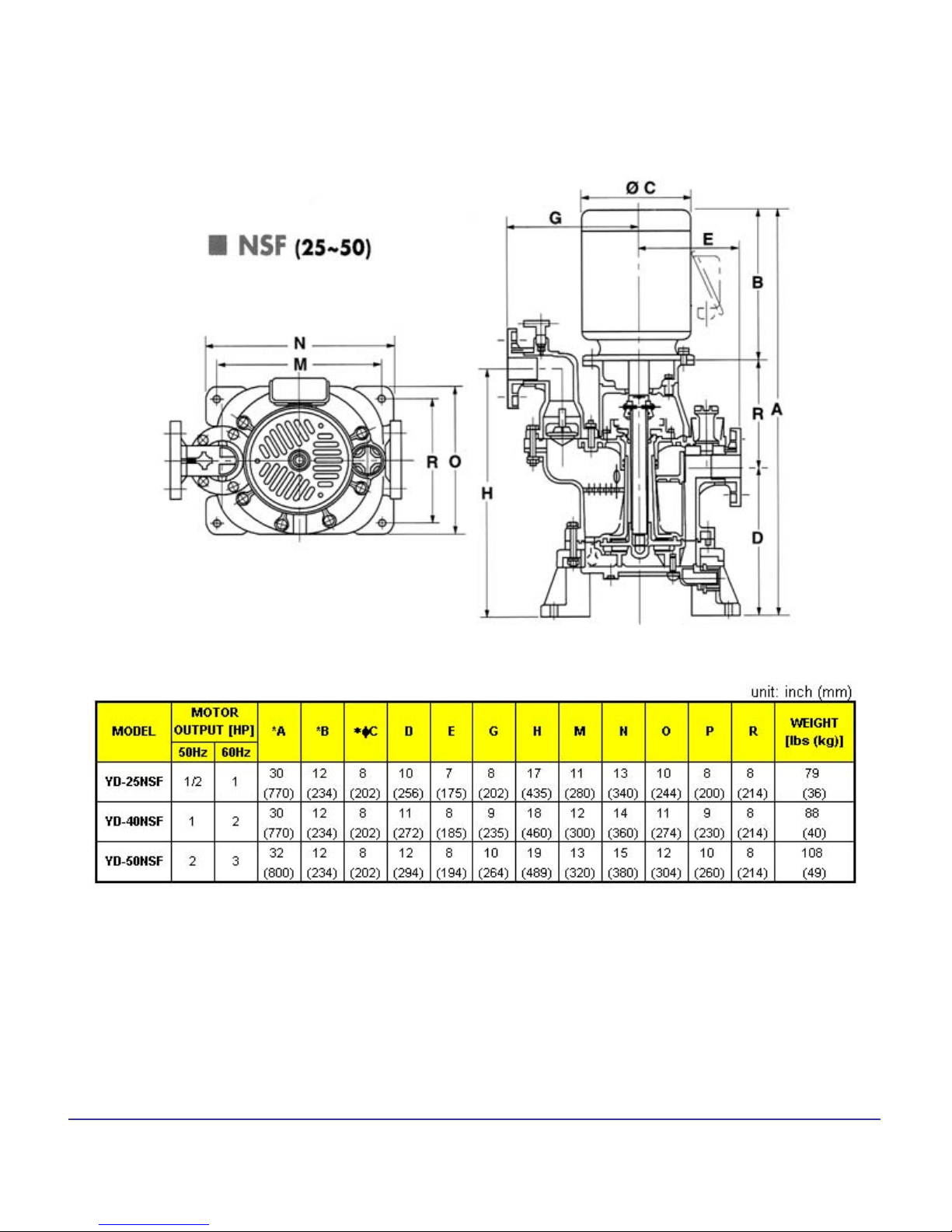
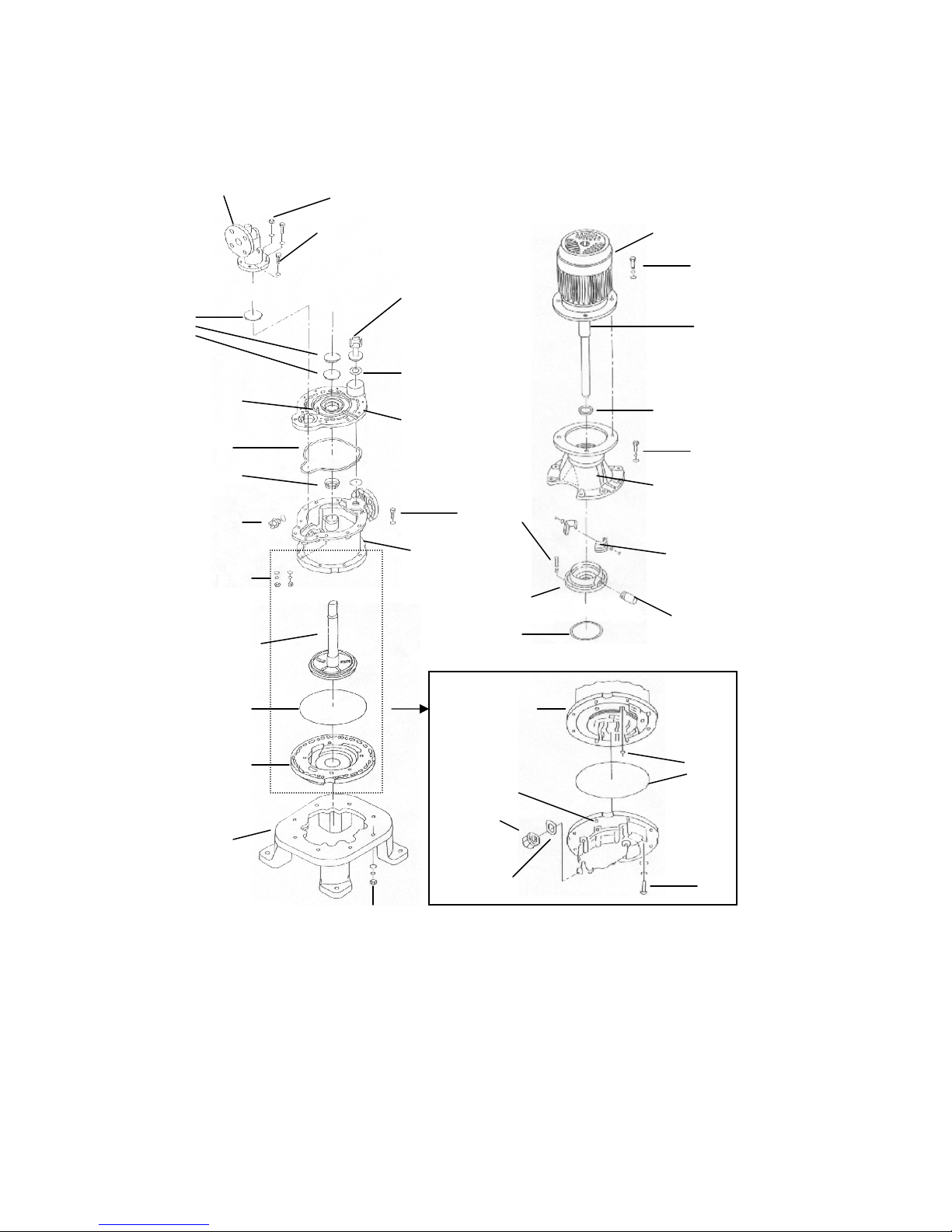
The NSF/SF series is a uniquely developed sealless and valveless self-priming
centrifugal chemical pump. The primed water that fills the whole interior of the pump
moves to the self-priming chamber guided by the impeller after the pump is turned on.
In the self-priming chamber, the air and water separate as they rotate. The water is
propelled into the impeller as it leaves the self-priming rotational outlet located on the
bottom of the pump, and continues its repetitive cycle of self-priming. Air from the
shaft is sealed by the seal blades during self-priming. As an added measure, a
balance hole is constructed on the casing to release air into the self-priming chamber,
ensuring that the self-priming operation is not affected. While the pump is not in use,
the siphon cut hole located on the interior of the self-priming chamber and the suction
chamber blocks the backflow from the siphoning action. Water that is necessary for
the subsequent prime remains in the suction chamber for smooth pumping
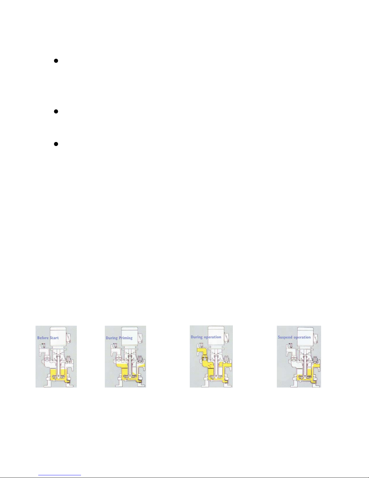
Pump is filled with
water.
Just as the pump is turned on,
the liquid in the suction
chamber is sucked up, as the
rotational movement creates
a stronger vacuum seal.
All of the air in the main body of
the pump is discharged and will
allow normal smooth operation.
Should even a little amount of air
enter, it will be discharged
without causing any operational
difficulty.
When the pump is stopped, the
siphon cut hole will minimize
the liquid backflow and secure
enough liquid in the suction
chamber for the next prime.

3
EXAMPLES OF USE
Pumping, transport from a drainage tank or
a chemical tank
2.
Transferring/circulating high temperature
plating liquid to a filtering tank
1.
!WARNING
THIS USE NOT
APPLICABLE.

4
SPECIFICATION AND PERFORMANCE CURVES

5
DIMENSIONAL AND PARTS DRAWING
Note: Marked (*) dimension varies depending on the motor size.

6
DIMENSIONAL AND PARTS DRAWING (continued)
O-ring
Discharge Elbow
Bolts and Washers
Priming Plug
Packing
Upper Flange
Dry Seal
Impeller with
Sleeve
O-ring
Casing
Assembly
Pump
Base
Motor
Oil Seal
Motor
Bracket
Impeller
Locking
Sleeves
Overflow
Pipe
O-ring
Pump Body
O-ring
Casing
Assembly
Drain Plug
Packing
Pump Body
Seal Case
Hex. Cap
screws
Pump Shaft
Hex. Bolts
Hex. Bolts
Hex.
Bolts
Nut for Stud Bolt
Cleaning
Plug
Hex. Bolts
Hex. Bolts
O-ring
Stud Bolt

7
DIMENSIONAL AND PARTS DRAWING
SUSBolts19
PVCOverflow pipe with PVC hose18
FPMDry seal17
CFRPP + CeramicSeal case16
CFRPPUpper flange15
CFRPPDischarge elbow14
Diallyl PhathalatePump base13
CFRPPCasing12
FPMPacking for drain & priming plug11
CFRPPDrain plug10
CFRPPImpeller with sleeve9
PPSImpeller locking sleeves8
FPMO-ring7
CFRPPCleaning plug6
CFRPPPump body5
CFRPPPriming plug4
SCS40Shaft slit collar*3
SUSMotor shaft*2
Diallyl Phathalate + FCMotor bracket*1
MATERIALPARTS NAMENO.
1,2 and 3 are used for either a MEMA motor or a motor with joint
shaft only.
*
(continued)

8
PRECAUTIONS IN HANDLING THE SELFREE
Remove the blind seals on the outlet and inlet of the pump before attaching pipes to
them.
Do not rotate the motor in the reverse direction. (Except for an instantaneous reverse
rotation to check the rotational direction.)
The pump has a patented structure to retain a certain amount of liquid in the casing
when the pump is stopped.
If liquid that foams easily is primed, it may take much time or make it impossible to
pump liquid, causing problems by generating heat.
If there is excess slurry, it will collect behind the impeller. This will mar the sealing
ability, causing the liquid leakage.
A liquid with a high specific gravity or a high temperature will take more time to prime.
In such cases, it is necessary to take some appropriate measures such as shortening
the length of the suction pipe.
Pumping the liquid with too much air will mar the self-priming ability. If the pump is
operated for extended hours in this condition, the liquid temperature will rise, causing
the pump and casing to be distorted and/or damaged by heat.
To prevent the self-priming capacity from lowering, it is necessary to have a vertical
pipe longer than 3.3 ft. (1 m) attached to the outlet, with a bypass pipe for air exhaust.
At the same time, it is also necessary to keep the pipe length as short as possible on
the suction side to minimize pipe resistance loss.
The height of suction may be decreased depending on the type of liquid used, the
liquid’s specific gravity, and the liquid’s temperature It is recommended to set the
height of suction at a relatively low level to allow for the possible decrease.
To prevent the pump from being distorted by thermal expansion and thereby also
prevent any liquid from leaking, it is imperative that the user equip the piping with
bends and expansions.
When using the pump to transfer waste liquid, it is imperative that the user equip the
suction hole with a strainer to prevent dust and other foreign matter from entering the
pump.
When moving the pump ( for transport or repair), it is necessary for the user to drain
the liquid and wash the pump with water completely to ensure safety.
Handle the pump carefully without any hard impact as its base is constructed of resin.

9
INSTALLATION AND PIPING
The pump can deliver the designed performance if its installation and piping are done
properly. In the case of a self-priming pump, it is especially necessary for air taken in
during self-priming operation to be exhausted smoothly and the primed liquids for the
subsequent operation remain in the pump. Following are installation and piping
guidelines for smooth pump operation:
1.Equip the outlet pipe with a valve and a check
valve.
2.The piping on the outlet should be a vertical
pipe of more than 3.3 ft. (1 m). It should also
be equipped with an air exhaust pipe with a
valve (d).
3.Limit of suction height (for clear water at room
temperature).
Check Valve
Approx.
3.3 ft. (1 m)
d
A
11.5 ft. (3.5 m)YD-50NSF
9.8 ft. (3.0 m)YD-40NSF
8.2 ft. (2.5 m)YD-25NSF
A
3.The limit of the suction height (self-priming
capacity) assumes that the suction pipe is
affixed vertical to the surface of the water
with ambient temperature (68 °F/20 °C). The actual self-priming capacity is
affected by liquid type, temperature, viscosity, and specific gravity. It is also affected
by the type and diameter of the suction pipe, the number of valves used, the mixture
of air from the flange and valves, and other factors. Actual piping should be made
by taking these factors into consideration.
4. It is necessary to provide the piping with two or more bends and expansion joints to
absorb thermal expansion and protect the pump from distortion or damage. Thermal
expansion is caused by the temperature of the liquids.

10
ORDER OF ASSEMBLY
Motor Assembly Pump Body Assembly
Installation of the joint shaft to the
motor
Installation of the motor bracket to
the motor
Installation of the shaft locking
sleeve to the motor
Installation of the o-rings to the
pump flange
Installation of the flange to the pump
body
Installation of the discharge elbow to
the pump body
Installation of the motor assembly to
the pump body
Installation of the impeller to the
pump body
Installation of the o-rings to the
pump body and the casing
Installation of the pump casing to
the pump body
Installation of the pump base, the
priming plug and the drain plug to
the pump
Overview

11
Motor Assembly:Installation of the joint shaft to the motor
ORDER OF ASSEMBLY (continued)
1. Install the joint shaft to the
motor.
2. Adjust the shaft run out by a
hummer.
3. Check the shaft run out by the
dial gauge.
The shaft run out should be
within 50 micrometer. Repeat
step 1 to 3 until the shaft run
out is within 50 micrometer.
As the pictures shown below, install the joint shaft to the motor and check the shaft run out the dial gauge.
Assemble the motor bracket to the motor by bolts. When you install the bracket to the motor, please be
careful about the direction of the bracket and the motor. The terminal box of the motor and the nameplate
should be the same direction.
The terminal box and
the nameplate should be
the same direction.
Fasten the motor and the
motor bracket with bolts.

12
Motor Assembly:Installation of the shaft locking sleeve to the motor
Install the shaft locking sleeves (2 pcs.) on the motor shaft with screw bolts. Do not tighten them at this time.
Rubber
The rubber portion must be
turned.
Pump Body Assembly: Installation of the o-rings to the pump flange
Place the following four o-rings onto each specified place on the pump upper flange.
O-ring for the priming plugPump upper flangeO-ring for the upper flange
ORDER OF ASSEMBLY (continued)
O-rings for the upper flange Please apply grease or some
lubricant when the o-rings for
the upper flange are placed.

13
Pump Body Assembly:Installation of the pump upper flange to the pump body
Pump upper flange
The pump body is put on the pump upper flange with o-rings. Weight the pump body for a certain installation.
When the pump upper flange is installed on the pump body, please be careful about the direction of each part.
Pump body
Pump Body Assembly:Installation of the discharge elbow to the pump body
The pump body is put on the pump upper flange with o-rings. Weight the pump body for a certain installation.
O-ring for the discharge elbow.
Place this o-ring first.
Nut with spring washer and
washer
Bolts with washer and nut with
spring washer and washer
Bolts with washer and nut with
spring washer and washer (at
the back side of the discharge
elbow).
ORDER OF ASSEMBLY (continued)

14
Pump Body Assembly: Installation of the motor assembly to the pump body
Place the pump body onto the motor assembly as a picture shown below.
The impeller and dry seal adjustment
Bolt with washer and nut with
spring washer and washer.
Bolt size: M10x65, Nut sieze:M10
Pump Body Assembly: Installation of the impeller to the pump body
Put the dry seal to the impeller up to a groove scribed on the sleeve.
The direction of
the dry seal
ORDER OF ASSEMBLY (continued)
Tighten the pump body and the motor assembly firmly with hex bolts and nuts.

15
The impeller gap adjustment
Install the impeller with the dry
seal to the pump
Insert the spacer washer on
a step of the motor shaft.
1.
Rotate the impeller until a hole
in the motor shaft appears,
and insert the tool into the
hole to hold the impeller, and
then tighten the impeller.
2. Measure a distance of Yfrom
the top of the impeller to the
top of the body. “Y” measures
as 0.827” (21 mm).
3. Measure a distance of Z
from the top of the casing to
the bottom of the casing. Z
measures as 0.858 “ (21.8
mm)
4.
The GAP calculation between the impeller and the casing
GAP = Z - Y 0.032 “ (0.8 mm)
MUST BE
Note: The gap between the impeller and the casing must be 0.032 “ (0.8 mm). If not, please repeat
step 1 thru 3 until the gap becomes 0.032” (0.8 mm).
Please fasten the impeller locking sleeve with screws after the gap is corrected.
If the gap is incorrect, the impeller might hit the casing or the pump body. It lowers the pump
performance and damages the pump.
ORDER OF ASSEMBLY (continued)

16
Pump Body Assembly: Installation of o-rings to the pump body and the casing
1. Place five o-rings onto the o-
ring grooves around the bolt holes.
2. Place an o-ring onto the o-ring
groove on the casing.
Pump Body Assembly: Installation of the pump casing to the pump body
1. Place the casing with o-rings onto the
pump body and fasten them with slotted
head screws and spring washers.
2. Please be careful about the direction of the casing when
installing it to the pump.
ORDER OF ASSEMBLY (continued)
This manual suits for next models
2
Table of contents
Other World Chemical Water Pump manuals
Popular Water Pump manuals by other brands

Dustcontrol
Dustcontrol DC Storm 500 Translation of the original instructions

Speck
Speck P52/22-600 operating instructions

SCOT
SCOT MOTORPUMP VAE Series Installation

EINHELL
EINHELL ROYAL RBP 18 Assembly and operating instructions

Pontec
Pontec PondoCompact 300 operating instructions

Viking pump
Viking pump 1224A-ASP Series Technical & service manual