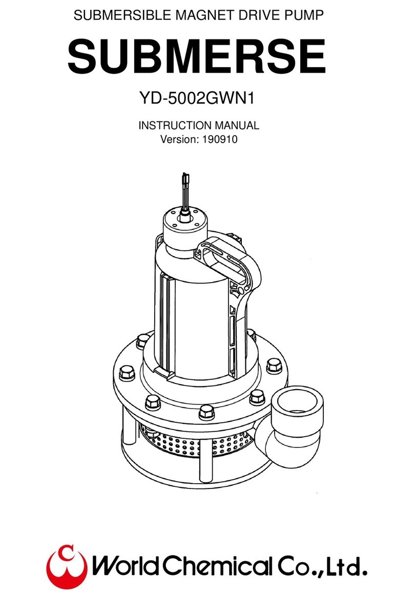
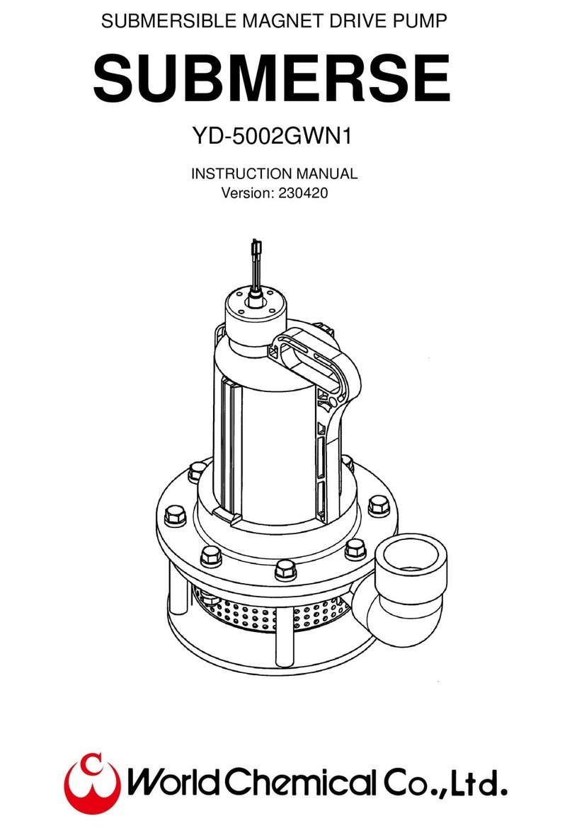
World Chemical SUBMERSE YD-5002GWN1-HP User manual

SUBMERSIBLE MAGNET DRIVE PUMP
SUBMERSE
YD-5002GWN1
INSTRUCTION MANUAL
Version: 171212

1
Preface
Thank you very much for purchasing World Chemical’s submersible magnet drive pump “SUBMERSE”.
To effectively use SUBMERSE for an extended period of time, it is necessary for the user to properly
operate and maintain the pump in accordance with the instruction manual.
Table of contents
Warning ........................................................................................................................................................ 2
Caution......................................................................................................................................................... 3
◼Model description / Specification .......................................................................................................... 4
◼Outline dimension ................................................................................................................................. 5
◼Features / Precautions in handling / Temperature to use..................................................................... 6
◼Minimum liquid level during operation / Example of installation / Model description........................... 7
◼Use........................................................................................................................................................ 8
◼Precautions in operation....................................................................................................................... 9
◼Disassemble / Assemble..................................................................................................................... 10
◼Exploded view......................................................................................................................................11
Troubleshooting.......................................................................................................................................... 12
Warranty / Repair ....................................................................................................................................... 12

2
Warning
When using for dangerous liquid or in atmospheres
When using the pump for dangerous liquid or in potentially explosive atmospheres (only explosion- proof
type), adhere to facility standards determined by law and check no liquid leak daily. If the pump is
operated under abnormal conditions such as liquid leak, it leads to explosion, fire or personal injuries.
Follow the manufacturers’instructions about handling the liquid.
Banning the use of damaged or modified pumps
If using the damaged of modified pump, it may cause personal injuries, electric shock or the pump
damage. They are not covered by warranty.
Caution in transporting and lifting pumps
Use the hoist bolt when lifting a pump. If it does not own the hoist, use a belt sling and lift the pump with
careful attention to the weight balance. Perform it by qualified personnel with the strong enough sling. The
weight of the lightest pump is approx. 23kg at least. Do not carry a pump by hand as much as possible,
because it may cause an accident.
Banning the operation with the power on
Do not check or disassemble a pump or motor while the power on. It leads to personal injuries from
electric shock or getting caught in the rotor. Take the multiple safety precaution such as the switch for
main power supply, the operation switch, and the hand switch for the pump.
Connection of an earth wire
Using the pump without connecting an earth wire may cause electric shock. Perform the connection by a
qualified person according to the electric facility’s technical standards and interior wiring regulations.
Protection of the power supply cord.
If stretching, pinching or damaging the power supply cords or motor lead wires, it causes fire or electric
shock for the damaged cable. Install the cover of the terminal box in its proper position after wiring.
Ground Fault Interrupter (GFI)
If using a pump without a ground fault interrupter device, it may cause electric shock. Prevent the
electric accidents and the pump damages applying circuit breakers, over-current protection devices
and/or other protective devices.
Caution in removing a pump
When removing a pump from pipes, close the suction and discharge pipe valves and check no liquid leak.
If direct contact with liquid, it may cause injury.Always wear protective gear when performing operations.

3
Caution
Banning the unspecified use
Do not use the pump for purposes other than those specified on the nameplate. Connect the pump after
checking the power specification of motor (phase, voltage and frequency). Unspecified use may cause
personal injuries or damages to the pump and peripheral equipment.
Restriction on persons handling a pump
Carry, install, wire, operate and maintain a pump by an expert who has full knowledge of the pump.
Caution in unpacking
Before opening the package, check the up side down.When it is a wooden crate, be careful to avoid injury
yourself from nails and slivers.
Ventilation
Do not obstruct ventilation around the motor to prevent to overheat it. If handling toxic or odorous liquids,
install the pump in a well-ventilated place to prevent symptoms of poisoning.
Repair and return
Contact your supplier or us to repair the damaged pump. When returning the pump by courier, clean up
the inside and outside of the pump by water. Pack it with a plastic bag after checking no liquid.
Plastic parts
The pump is made of plastic. If it receives strong impact, it may damage and lead to personal injuries. Do
no hit and climb on it. Install a piping support to prevent the piping load.
Pump start-up
Check the rotational direction when initially starting up the pump. Open the suction and discharge valves
and check is no liquid leak from the pipe connection. Then, turn on the switch instantly after releasing air
from the pipe and filling the liquid in the pump, and check the rotational direction. For reverse rotation,
switch two of the three phases in the three-phase power supply. Before this, turn off the power supply and
ensure safety.
Disposal of pump
When dispose the used pump, remove adhered liquid and dispose it as the industrial waste in accordance
with the law.
Leak protection
Take appropriate preventative measures in consideration of possible leakage for the pump and pipe
damage.

4
◼Model description / Specification
Model: YD-5002GWN1
YD-5002GWN1-HP (High pressure type, Only 60Hz)
Type: Chemical Submersible Magnet Drive Pump
Name: SUBMERSE
◼Specification
Total head Capacity
5002GWN1 60Hz 8.3m (27ft)
200L/min
(52gpm)
5002GWN1-HP 60Hz 11.9m (39ft)
100L/min
(26gpm)
23kg
(50lbs)
Weight
200/220V/460V
60Hz
Standard performance
50mm (2")
1.1kW
Model
Frequency
Output
Power
Discharge
bore
Dry three phase
induction motor
H
1.1kW (1.5HP)
3
Maximum 2
Standard
Maximum
Standard
Outline
Height
lbs Direct
58F
Starting
current
Rated
current
Rated
voltage
Pole
200/220V/460V
60Hz
Attached cable
Thermal protector
CFR PP
50A (2")
5002GWN1
5002GWN1-HP
Incorporated in the motor
Liquid temperature
(Max)
Rotating
speed
1.25 m㎡x 10m (0.049 x 32ft)
2PNCT 4 cores
23kg (50lbs)
Main material
Bore
Model
Frequency
Weight
ft
gpm
Inch
Capacity
Total
head
Motor
Method of starting
Pump
Type
Insulation
Rated output
Phase
Dimension
Others
15" x 9.8" x 16"(H)
60Hz
11.5
8.3
330
200
60Hz
47
39
79
26
60Hz
3370min-1
60Hz
4.75A/4.38A
60Hz
23.03A/22.73A

5
◼Outline dimension
No. Parts name Reference No. Parts name Reference
1 Motor FC 15 Set bolt 92 CFR PP
2 Motor magnet Ferrite 16 Set bolt 52 CFR PP
3 Motro magnet key SS 17 Nut for set bolt CFR PP
4 Motor magnet nut SS 18 O-ring for set bolt FPM / EPDM
5 Cabtyre cable 2PNCT 19 Floating washer
PTFE (Only Ceramic
bearing)
6 Motor cover CFR PP 20 Stand bolt HT, PVC
7 Impeller CFR PP 21 Strainer PP
8 Impeller magnet Ferrite 22 Sludge fence PP
9 Front bearing PTFE / Ceramic 23 Bottom plate PP
10 Rear bearing PTFE 24 50A Valve socket PVC
11 Separating board Ceramic
12
O-ring
for separating board
FPM / EPDM
13 Casing CFR PP
14 Shaft SiC
* When the temperature of the liquid is high (55 degrees and more), do not use No. 24: Valve socket
(PVC). If using a valve socket, HT-PVC valve socket is recommended.
A-A
Elbow: Thread
Strainer
φ3

6
◼Features / Precautions in handling / Temperature to use
SUBMERSE is constructed of Carbon Fiber Reinforced Polypropylene and a corrosion resistant ceramic
shaft. Additionally, the structure is a magnet drive type which does not require a shaft seal. It makes the
submersible pump use for strong acids and alkalis that the pump did not use to be used for.
1. All wet kit parts are made of corrosion resistant resin and ceramic.
2. The pump can be used for strong acids and alkalis.
3. It is a magnet drive structure which does not require a shaft seal. The liquid enters into the motor.
4. There is little consumables and it is easy to replace parts.
5. Operation of the pump is as simple as lowering it into a tank. It is also possible to operate with
hanging.
6. The pump has a handling for carrying and be suitable for emergency use.
7. There is a ceramic plate between the motor and pump chamber to be resistant to heat and chemical.
8. A thermal protector is incorporated. If overload occurs from any cause, the motor is stopped by the
thermal protector.
◼Precautions in handling
1. Slurry accelerates the bearing worn. Especially when the pump is used in a settling tank, mount the
pump to prevent slurry entering or clear slurry. (Replacement of the bearing is easy and use the
ceramic bearing for liquid with slurry.)
2. Completely submerge the pump to use. Operation in air causes the pump damage.
3. Operation with the check valve at the discharge pipe leads dry running not to release air. Install the
air release pipe beneath the check valve and always release air.
4. If the pump is exposed from liquid, the motor resin cover may be damaged because the motor is not
cooled.
5. It may cause dry running for the failure of the liquid level gauge. Check it before use.
6. Make sure to put the strainer to prevent dirt and always clean it not to be clogged. If it is clogged, the
pump may burn not to pump.
7. When extending the electric wire, consider the diameter to prevent to decrease the voltage.
8. The temperature of the liquid is high (55C/131F degrees and more), change the material of the valve
socket (PVC) at the discharge outlet. (HT-PVC is recommended.)
9. Do not use the pump for highly concentrated sulfuric acid (50% and more).
◼Temperature to use
YD-5002GWN1: 70C/158F degrees (MAX.) Cable material: 2PNCT

7
◼Minimum liquid level during operation / Example of installation / Model description
Minimum liquid level during continuous operation is 400 mm.
Keep the liquid depth during operation that the whole pump is submerged.
Operation under the liquid level of the continuous operation for dead head operation is within 5 minutes.
Do not short operation repeatedly.
⚫The thermal protector may work to protect the motor according to conditions in the operation and
the pump may stop. In this case, stop the operation for a while. Ensure the liquid level is properly
and start the operation after checking whether the pump is normal.
Minimum liquid level during operation is 130 mm.
⚫Even if the operational liquid level is correct, the operation error may occur to the air entering by the
condition of the liquid level.
⚫If the impeller is operated in the air, the rotating parts may be damaged.
◼Example of installation
◼Model description
YD –50 02 GWN1 –CP –A D 6 2 –HP - V
(1) (2) (3) (4) (5) (6) (7) (8) (9)
(1) Bore: 50 = 50A
(2) Motor output: 02 = 1.1kW = 1.5HP
(3) Cover main material: CFR PP
(4) Bearing material: R = PTFE A = Alumina Ceramic
(5) O-ring material: E = EPDM D = FPM
(6) Frequency: 5 = 50Hz 6 = 60Hz
(7) Specific gravity: 1 = 1.1 3 = 1.3 5 = 1.5
(8) Impeller: No mark = Standard type HP = High pressure type
(9) Special mark: (Ex.) V = Non-standard voltage Z = With PVC tube
* When the special mark is suffixed, it means the special material required by customer or special
specification with some modification.
Pressure gauge
Sluice valve
Check valve
Air release pipe
(Open slightly)
Min. liquid level
during continuous
operation
Operational min.
liquid level

8
◼Use
1. For pumping liquid and waste liquid from a deep or narrow pit or tank.
2. For pumping up easy bubbling liquid.
3. For pumping up chemical liquid from a sealed tank.
4. For circulating liquid in a tank.
5. For mixing liquid in a tank or an equipment.
6. For pumping and transferring liquid in emergencies.
Sample of use
Pumping liquid from a
deep tank
Pumping easy bubbling
liquid from a shallow tank
Pumping liquid from a
narrow and deep tank
Scrubber system
(Washing system)
Using for a truck
For mixing

9
◼Precautions in operation
1. Electric wiring
Before starting operation, check the rotational direction. When U (red), V (white), W (black), and earth
(green) are connected, the pump starts. Checking the rotational direction is as follows.
1-(1) In case of the inverse rotation, the capacity is only 30% of the forward rotation.
1-(2) When turning on the switch with lifting the pump in water, a counterclockwise back action is in
the forward direction.
Note: In case of the inverse rotation, switch two of three cables (Rec, White, Black).
2. Precautions in electric wiring
⚫Make sure to connect a green earth wire to a polar plate or bar before connecting the cable to
prevent electric shock.
⚫When it is necessary to be the instantaneous operation to check the rotational direction, never
test the pump in air. Heat makes the pump may deform and causes the failure.
⚫Install a circuit breaker to prevent unexpected problems.
Note: To prevent electrical shock or fire, the user is obligated to provide a leak breaker
according to the industrial safety and Health Regulation and Electric Equipment Technical
Standard. (Japan)
Red –U
<Cable side> White –V <Motor cable side>
Black –W
Green –Earth
3. Voltage during operation
When the voltage is low, the current increases. In this case, the thermal protector works as the
temperature of the stator is raised. The low voltage causes the performance failure. Use the pump
with the voltage within the specified range.
Note: The applicable voltage for this pump is within ±10%of the rated voltage.
4. Thermal protector (Protection Instrument)
When the temperature of the motor coil is near burning temperature for electrical or mechanical
causes, the burn protection function works and stops the motor by cutting off the electrical circuit. At
this time, carefully check the operated cause of the thermal protector, and remove it before resuming
operation.
Note: Make sure to turn off the power before check. The thermal protector automatically
restart.
Positive rotation
Inverse rotation

10
◼Disassemble / Assemble
1. Remove 4 pcs of the set bolt 52 (16) from the stand bolt (20) to fix the casing (13).
2. The bottom board (23) with the stand bolt (20) and the strainer (21) are separated.
3. After removing the other set bolts (15) (16), place the entire pump horizontally and pull the casing
(13) to separate. The impeller (7) is secured to the motor cover (6) through the separating board.
4. Remove the O-ring for separating board (12) and move the impeller attached to the driving side
magnet (2) outward to remove.
⚫Do not disassemble the motor (including the cable). When an overhaul of the motor is required,
contact your supplier.
◼Assemble
1. Place the O-ring for separating board (12) in the grove of the motor cover (1) and put the separating
board (11) on the motor cover (6).
2. Slide the impeller (7) from the edge of the separating board (11) to the center. In this case, do not to
slide the impeller quickly to the center. The impeller (7) may be pulled toward the motor magnet (2) by
magnetic force and make an impact to the separating board (11). Then, the separating board (11)
may be damaged.
3. Set the stand bolt (20) on the bottom board (23), put the strainer (21) and put the casing (13) on. In
this case, install the O-ring for set bolt (18) to the stand bolt (20).
4. Install the O-ring for separating board (12) in the casing (13) and put the assembling 1 & 2 on.At that
time, insert the bearing of the impeller (7) with the outer diameter of the pump shaft (14).
5. Finally, fix it with set bolts (15) & (16).
In this case, set the O-ring for set bolt (18) to the nut for set bolt (17). When setting, fix the nut or set
bolt (17) firstly and fix the stand bolt (20).
⚫When tighten the set bolts (15) & (16), the torque is 8N・m.

11
◼Exploded view
6
6

12
Troubleshooting
1. Unable to pump or insufficient pumping
2. Motor overheats
3. Pump vibrates
WORLD CHEMICAL USA (“WCUSA”)
Unable to pump or insufficient pumping
Insufficient discharge volume
and pressure
Unable to pump even after opening
Discharge valve
Unable to pump even after pouring
priming liquid into the pump
Pump
rotates in
reverse
Air in the
suction pipe
Resistance
in the
discharge
pipe
Air enters
from the
suction
pipe/connecti
on section
Magnet
coupling
loses
Lack of
priming
liquid
Foreign
object in the
suction pipe
Replace
motor wiring
Inspect the
piping
Remove the
foreign
object and
inspect any
damage of
piping
Inspect the
connection
section and
liquid surface
in a tank
Inspect no
foreign
object in the
pump
and
estimate
whether it is
overload or
not
Pour
priming
water and
eliminate all
air in the
pump
Clean the
suction pipe
Motor overheats
Overheat
Inspect to see if the correct specific
gravity and viscosity are used
Verify to see if the correct voltage
and frequency are used for the
motor
Operating temperature is high
Turn down the operating temperature
Pump vibrates
Unstable
installation
place
Looseness
bolts for
pump
installation
Foreign
object in the
suction pipe
Worn
bearing of
the pump
Damaged
shaft
Contact
between
impeller and
stationary
Worn
bearing of
the motor
Re-install
the pump
Tight bolts
Remove the
foreign
object and
clean up
Replace the
part
Replace the
part
Replace the
part
Replace the
bearing or
the motor
Min. liquid level is low
Increase the min. liquid level

13
STANDARD ONE-YEAR LIMITED WARRANTY
FOR SALES MADE ONLY IN THE UNITED STATES, CANADA
This limited warranty completely replaces the warranty issued by World Chemical Co., Ltd.
relating to the below described Pumps.
WCUSA warrants its Magnetic Drive Pumps, Self-Priming Pumps, Oil Skimmer Systems, Vertical
Pumps and Submersible Pumps (“Pumps”) against defects in materials and workmanship for one
year from the date of WCUSA’s invoice to you for the affected Pump. This warranty requires you
to return the Pump to WCUSA.
If there is a manufacturing defect, WCUSA will replace or repair the Pump with new or rebuilt parts
at no charge to you. Please return the Pump to: World Chemical USA, 30 Hughes, Ste 203, Irvine,
CA 92618.
When returning the Pump, include your name, address, daytime telephone number, and a description
of the problem. No warranty work can be performed without this information.
Properly pack the Pump (preferably in the original carton) to prevent damage to the Pump in transit.
The repaired or replaced Pump will be warranted for a period equal to the remainder of the original
one-year warranty.
All replaced Pumps, parts and components, shall become the property of WCUSA
This Limited Warranty does not cover: (a) defects or damage resulting from accident, misuse,
abnormal use, abnormal conditions, improper storage, exposure to dirt, neglect, or unusual physical,
electrical or electromechanical stress; (b) scratches, dents and cosmetic damage, unless caused by
WCUSA; (c) Pump that has the serial number removed, defaced, damaged, altered or made illegible;
(d) ordinary wear and tear; (e) defects or damage resulting from the use of Pump in conjunction or
connection with other equipment not furnished or approved by WCUSA; (f) defects or damage
resulting from improper testing, operation, maintenance, installation, service, caused by the use of
unauthorized parts of service; (g) defects or damage resulting from external causes such as collision
with an object, fire, flooding, dirt, windstorm, lightning, earthquake, exposure to weather conditions,
or improper use of any electrical source; (h) irregularities or breakdowns due to chemical or
hydrodynamic corrosion by liquid. We do not warrant the chemical resistance of the Pump to any
chemical or to corrosion.
You will be responsible for paying for your own shipping costs for delivering the Pump to us. If we
determine the Pump is covered by this warranty, we will return the new or repaired Pump to you at
our expense. If we determine that the Pump is not covered by this warranty, we will return it at
your expense.

14
WCUSA does not warrant accessory components, including, but not limited to, Impeller (including
mouth ring and bushing), Rear Casing set (include shaft), O-Ring for Casing and other consumable
parts.
REPLACEMENT OR REFUND OF THIS PUMP AS PROVIDED UNDER THIS LIMITED
WARRANTY IS BE YOUR EXCLUSIVE REMEDY.
WE ARE NOT RESPONSIBLE OR LIABLE FOR ANY LOSS, INCONVENIENCE OR DAMAGE,
WHETHER SPECIAL, DIRECT, INCIDENTAL, CONSEQUENTIAL, OR OTHERWISE, AND
WHETHER KNOWN OR SHOULD HAVE BEEN KNOWN TO US, INCLUDING LOST
PROFITS, GOODWILL, DAMAGE TO OR REPLACEMENT OF OTHER PUMPS AND
PROPERTY AND PERSONAL INJURY RESULTING FROM ANY BREACH OF WARRANTY,
THE INABILITY TO USE THE PUMP OR UNDER ANY LEGAL THEORY IN CONTRACT OR
TORT. THESE WARRANTIES AND REMEDIES ARE YOUR SOLE AND EXCLUSIVE
WARRANTIES AND REMEDIES IN CONNECTION WITH THE SALE AND USE OF THE
PUMP. NO OTHER WARRANTIES, ORAL OR WRITTEN, EXPRESS OR IMPLIED, ARE
GIVEN. OUR LIABILITY IS LIMITED TO THE ACTUAL PURCHASE PRICE YOU PAID TO
THE RETAIL SELLER OF THE DEFECTIVE PUMP. EXCEPT TO THE EXTENT PROHIBITED
BY LAW, ANY IMPLIED WARRANTIES OR CONDITIONS OF MERCHANTABILITY AND
FITNESS FOR A PARTICULAR PURPOSE ARE LIMITED IN DURATION TO THE DURATION
OF THIS LIMITED WARRANTY.
Some states do not allow the exclusion or limitation of implied warranties or liability for incidental
or consequential damages, or do not allow a limitation on how long an implied warranty lasts, so the
above limitations or exclusions may not apply to you. You are advised to contact applicable state
laws for a full determination of your rights. This warranty gives you specific legal rights, and you
may have other rights which vary from state to state.
No dealer, agent or employee is authorized to make any modification, extension, change or
amendment to this warranty. This warranty may not be assigned without the prior expenses written
approval of WCUSA.

15
Repair
If any irregularity is detected during operation, stop the pump and check it. Refer to the section on
“Troubleshooting”.
1. To request a repair service, ask your supplier or us.
2. Before requesting a repair service, read this instruction manual carefully and check it, again.
3. When requesting a repair service, provide the following information:
⚫Pump model and serial number
⚫The period of use and the condition
⚫The failure parts and the condition
⚫Type of liquid (name, specific gravity, temperature, any slurry or not)
Clean the inside of the pump adequately when returning it, because if the residual liquid leaks out during
shipment, it creates a hazardous condition.
Use names in the parts table (P6) to order for replacement or spare parts. Nevertheless, also provide the
part number and the material just in case.
Model:
Purchase date:
Serial No.
Date to start:
Supplier:
Notice: When repairing, consult your supplier. Wash the wet parts kit for the returned pump adequately
and pack it.

16
WORLD CHEMICAL CO., LTD. / Japan
Head Office / Overseas department
3F.,ANTEX24, 1-1-14, Taito. Taito-ku, Tokyo, 110-0016 Japan
TEL : 03-5818-5130 FAX: 03-5818-5131 (Head office)
TEL : 03-5818-5131 FAX : 03-5818-5131 (Overseas department)
Osaka Office
7F., KUJO Bldg., 1-27-6, Kujo, Nishi-ku, Osaka-shi, Osaka, 550-0027 Japan
TEL : 06-6584-3185 FAX: 06-6584-3160
Nagoya Office
1F., EIKEI Bldg., 1-307, Yashirogaoka, Meito-ku, Nagoya-shi,Aichi, 465-0051 Japan
TEL 052-701-1227 FAX 052-701-1250
Tsukuba Factory
6127-5, Onogo-machi, Joso-shi, Ibaraki, 300-2521 Japan
TEL 0297-24-1071 FAX 0297-24-1075
WORCHEMI TAIWAN CO., LTD. / Taichung, Taiwan
No.915, Zhongshan Rd., Shengang Dist., Taichung City 42955, TAIWAN
TEL 886-4-2562-8358 FAX 886-4-2562-8351
WORLD CHEMICAL USA, INC. / California, U.S.A.
30 Hughes, Suite 203, Irvine, CA92618, U.S.A.
TEL 1-949-462-0900 FAX 1-949-462-0999
SUZHOU WORLD TECHNOLOGY CO., LTD. / Jiangsu, China
402, Fu Yuan Road, Xiang Cheng Economic District, Suzhou, Jiangsu Province, China
TEL 86-0512-6579-8212 FAX 86-0512-6579-8215
This manual suits for next models
1
Table of contents
Other World Chemical Water Pump manuals
Popular Water Pump manuals by other brands

Pentair
Pentair myers aplex Series Installation and service manual

STA-RITE
STA-RITE D125 Series Installation, Operation & Parts Manual

Mouvex
Mouvex CC8-80 F Installation operation & maintenance

Edwards
Edwards STP-iXA3306C manual

Equalizer
Equalizer HP350SD Operator's instruction manual

Leader Pumps
Leader Pumps DIVERTRON user manual

Graco
Graco 203872 Instructions-parts list

WELCH-ILMVAC
WELCH-ILMVAC 2585B-01 owner's manual

EasyPro
EasyPro EX3600 Installation and service manual

Pentair
Pentair FAIRBANKS NIJHUIS 5410 Installation, operation and maintenance manual

Edwards
Edwards D372-15-805 instruction manual

Mallory
Mallory COMP PUMP 5110FI installation instructions