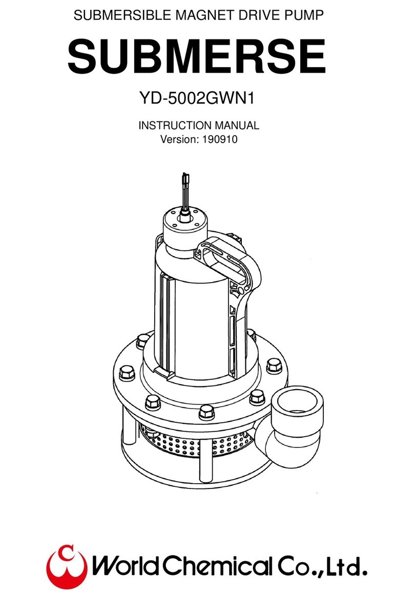
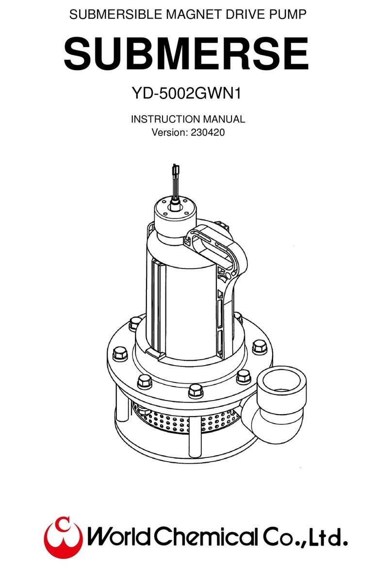
World Chemical Super Mag YD-GV Series User manual

Corrosion Resistance Magnet Drive Pump
YD-GV(F)
INSTRUCTION MANUAL
Version: 151119

1
Preface
Thank you very much for purchasing World Chemical’s magnet pump “Super Mag”. Please read this
manual thoroughly. An adequate understanding of this manual is required to maximize the pump’s
performance and to assure safety and long-term efficiency. Store this manual where it can be easily
accessed.
Table of contents
Safety precaution (To be observed at all times)........................................................................................... 1
Unpacking check / Model description .......................................................................................................... 4
Specification / Outline dimension................................................................................................................. 6
Parts name / Material / Structure................................................................................................................ 10
Handling instructions.................................................................................................................................. 12
Installing / piping precaution....................................................................................................................... 13
Operating precaution.................................................................................................................................. 14
Maintenance / Consumable parts YD-20Y6GV1 / 20A6GV1 .................................................................... 15
Disassembly / Assembly YD-20Y6GV1 / 20A6GV1................................................................................... 16
Exploded view YD-20Y6GV1 / 20A6GV1 .................................................................................................. 16
Maintenance / Consumable parts YD-250* / 400* / 500*GV(F)* series .................................................... 17
Disassembly /Assembly YD-250* / 400* / 500*GV(F)* series................................................................... 18
Exploded view 250* / 400* / 500*GV(F) series ....................................................................................... 22
Troubleshooting.......................................................................................................................................... 23
Warranty / Repair ....................................................................................................................................... 24
Safety precaution (To be observed at all times)
The following procedures are intended to protect you from personal injury and/or property damage.
⚫The following symbols classify the
degree of danger and explain the
damages that could occur when its
contents are ignored or the pump is
used improperly.
⚫Safety rules to be observed are classified
and explained under the following symbols.
(The following are examples of picture
displays)
Warning
Caution
Non-compliance can
lead to fatal or serious
injury.
Non-compliance can
lead to some injury
and/or property damage.
This symbol cautions people
to be careful.
This symbol signifies that this
action must not be taken.
This symbol indicates that the
action must be taken.

2
WARNING
(1) Dangerous liquids and surroundings.
When using the pump for dangerous liquids or in surroundings (only explosion prevention
specifications), adhere to facility standards determined by law and conduct daily check to prevent
leakage. If operate the pump under abnormal conditions, such as liquid leakage, it may cause
serious accidents such as explosion or fire and personal injury. Regarding handing liquid, follow the
liquid manufacturer.
(2) Do not use damaged or modified pumps.
Using the damaged or modified pumps may cause fatal accident, electric shock or pump damage. It
is not covered by our warranty.
(3) Caution when transporting or lifting the pump.
Always use the hoist belt for pumps that come with them. When pumps do not have hoist belts, lift
them with bolt slings while watching the weight balance. It should be performed by qualified
personnel with enough strong slings. The lightest pumps’weight is around 10kg (22 lbs.), and do not
carry the by hands as much as possible.
(4) Do not operate pumps with power on.
Do not inspect or dismantle pumps or motors with the power on. It may lead to personal injuries such
as electric shock or getting caught in the rotor. Operate it with multiple safety devices such as the
switch for main power supply, the operation switch, and the hand switch for the pump.
.
(5) Connecting earth cable.
If using the pump without connecting earth cable to the motor, it may cause electric shock. Connect it
by qualified personnel under the electric facilities’ technical standards and interior wiring regulations.
(6) Protect power supply cord.
Over-stretching, pinching and damaging power supply cords or motor lead wires may cause fire or
electric shock to damage it. Place the terminal box cover at the original position.
(7) Install Current Leak Circuit Breaker.
The operation without a current leak circuit breaker may cause electric shock. Install it or an over
current protection device and prevent electric accidents or pumps damage.
(8) Caution when removing pump.
When removing the pump from piping, make sure to close valves on the suction/discharge piping and
check no liquid leakage. Direct contact with liquid may be harmful and wear protective gear when
performing operation.
The hole on the bracket is for the check of the coupling rotation state when installing/removing the
coupling with the motor shaft or maintenance.

3
CAUTION
(1) Unspecified use.
Do not use pumps for purposes other than specification in the spec sheet or the nameplate.
Especially, check the motor specification (phase, voltage and frequency). Unspecified use may cause
personal injuries, the pump or peripheral equipment damage.
(2) Restrictions of operator.
Transportation, installation, wiring, operation, servicing, and inspection should be performed by
qualified personnel who have full knowledge on the handling the pump.
(3) Caution when opening package.
Open the package after checking upside down of the product. When opening a wooden crate, be
careful of nails and silvers to get the product out without hurting you.
(4) Ventilation.
Do not place objects around the pump that might obstruct ventilation as the motor heats up. In
handling toxic or odorous liquids, have the pump situated in a well-ventilated place to prevent
poisoning.
(5) Repairs and returning the pump.
When repairing the damaged pump, contact your supplier. If sending the pump back by express,
wash the interior and exterior with fresh water and check it without liquid. Then, wrap with a vinyl bag
and pack it.
(6) Plastic (resin) parts.
The pump is made of resin and it may cause fatal accident for strong impact. Do not hit and get on
top of the pump.Also attach piping supports not to apply any pipe load to the pump.
(7) Pump starting.
Check the direction of rotation at the starting up of the pump. In this time, open the suction and
discharge valves and check no liquid leakage from the pipe connection. After exhausting air and
filling the pump with liquid, check the direction of rotation by switching quickly. If the rotation is in
reverse, switch two of the three phases in the three-phase power supply to change the direction of
rotation. Make sure to power off before wiring it.
(8) Disposing of scrapped pump.
When disposing scrapped pumps, remove adherent liquid and discard it as industrial waste in law.
(9) Outflow protection.
Just in case liquid leaks to break the pump or pipes, take appropriate preventative measures.

4
Unpacking check / Model description
Check as follows and contact your supplier when you have any questions.
1. The indication in the nameplate (model, total head, capacity, motor specification, voltage and motor
specification) is the same as your order.
2. Accessary is stocked with.
3. There is any damage and loose bolts during transportation.
Model description
YD –20 Y6 GV 1 –CP –R D 5 2
(1) (2) (3) (4) (5) (6) (7) (8) (9)
(1) Suction / Discharge Bore: 20A
(2) Motor output / Power Supply
Y6: 3 Phase 200V 0.26kW (Indoor motor)
A6: 1 Phase 100V 0.26kW (Indoor motor)
(3) Model GV: Self-priming pump
(4) Motor type 1:IE1
(5) Wet Parts Kit Material
CP: CFR-PP (Carbon Reinforced Polypropylene)
(6) Bearing Material R: CFR-PTFE
(7) O-ring Material
D: FPM (Dai-el) E: EPDM
(8) Frequency
5: 50Hz 6: 60Hz
(9) Limit of Specific Gravity
2: Until 1.2
YD –4001 GV 3 –GP –CD 5 1
(1) (2) (3) (4) (5) (6) (7)
(1) Bore / Motor output (3 phase, 200V)
Model
Suction bore
Discharge bore
Motor output
2500GV1
25A (1”)
25A (1”)
0.4Kw, 3/4HP
2501GV(F)3
25A (1”)
25A (1”)
0.75kW, 1HP
2502GV(F)3
25A (1”)
25A (1”)
1.5kW, 2HP
4001GV(F)3
40A (1.5”)
40A (1.5”)
0.75kW, 1HP
4002GV(F)3
40A (1.5”)
40A (1.5”)
1.5kW, 2HP
4003GV(F)3
40A (1.5”)
40A (1.5”)
2.2kW, 3HP
5002GV(F)3 (50Hz only)
50A (2”)
50A (2”)
1.5kw
5003GV(F)3
50A (2”)
50A (2”)
2.2kW, 3HP
5005GV(F)3
50A (2”)
50A (2”)
3.7kW, 5HP
(2) Model (3) Motor type (4) Main material
GV 1: IE1 GP: GFR PP
GVF 3: IE3 CF: CFR ETFE
YD-20Y6GV1 / 20A6GV1
Model
Capacity
THD
Serial No.
25* / 40* / 50*GV(F) series
YD-250*/400*/500*GV(F) series

5
(5) Bearing / O-ring material (250*/400*/500*GV(F) *series)
Model
YD-****GV(F)*-△△
Material code
CD
CE
AD
AE
TT
Bearing
Carbon
Carbon
Almina ceramic
Almina ceramic
Special*1
O-ring
FPM (Dai-el)
EPDM
FPM (Dai-el)
EPDM
Special*1
*1) Special material: The material other than the standard material is used by consultation with the customer.
(6) Frequency
5: 50Hz 6: 60Hz
(7) Limit of specific gravity
1: 1.05/1.1 2: 2.2 3: 1.3 4: 1.4 6: 1.6 8: 1.8 G: 2.0
250*GV* series
Code/Model
2500GV1
2501GV3
2502GV3
50Hz
60Hz
50Hz
60Hz
50Hz
60Hz
No indication
1.05
1.05
-
1.1
-
-G
-
2.0
1.8
-
2.0
400*GV3 series
Code/Model
4001GV3
4002GV3
4003GV3
50Hz
60Hz
50Hz
60Hz
50Hz
60Hz
No indication
1.1
-
-
1.1
-
-G
-
1.8
-
-
1.4
500*GV3 series
Code/Model
5002GV3
5003GV3
5005GV3
50Hz
60Hz
50Hz
60Hz
50Hz
60Hz
No indication
1.1
-
1.1
1.1
-
1.2
-G
-
1.4
-
1.8
1.6
250*GVF3 series
Code/Model
2501GV3
2502GVF3
50Hz
60Hz
50Hz
60Hz
-F
-
1.1
-
-G
2.0
1.6
-
1.8
400*GVF3 series
Code/Model
4001GVF3
4002GVF3
4003GVF3
50Hz
60Hz
50Hz
60Hz
50Hz
60Hz
-F
1.1
-
-
1.1
-
-G
-
1.6
-
-
1.3
500*GVF3 series
Code/Model
5002GVF3
5003GVF3
5005GV3
50Hz
60Hz
50Hz
60Hz
50Hz
60Hz
-F
1.1
-
1.1
1.1
-
1.2
-G
-
1.4
-
1.8
1.6

6
Specification / Outline dimension
◼20**GV1 series
Model
20Y6GV1
20A6GV1
Bore (Suc. x Dis.)
20A (0.8”) x 20A (0.8”)
(Union connection)
Motor output
0.26Kw (1/3HP) (Indoor motor)
Standard spec.
(m_L/min)
50Hz
6 –30
60Hz
7 –30, 22ft-7.9gpm
Weight: kg, lbs.
10.0 / 22
Limit of self-priming height (Normal temperature)
2.5 m/ 8.2ft
* Motor is indoor type. If the pump is used outside, consult us.
Outline dimension YD-20Y6GV1 / 20A6GV1
■GV Series

7
◼250*GV(F)* series
Model
2500
2501
2502
GV1
GV3
GVF3
GV3
GVF3
Bore (Suc. x Dis.)
25A (1”) x 25A (1”)
Motor output
0.4kW
(1/2HP)
0.75kW (1HP)
1.5kW (2HP)
Standard
spec.
(m_L/min
50Hz
No ind.
(-F)
8 - 80
-
-
-G
-
8 - 80
8 - 80
-
60Hz
No ind.
(-F)
-
Max:62ft,31gpm
Max:59ft,29gpm
-
-G
-
Max:59ft 29gpm
Max:39ft 22gpm
Max:63ft 31gpm
Max:59ft31gpm
Weight: kg, lbs.
GV
18.5
20.5/ 45
24.5/ 55
GVF
-
23/ 50
27/ 59
Outline dimension YD-2500GV1 / 2501 / 2502GV(F)3
A
B
C
D
E
F
G
H
I
J
K
L-ΦM
N
2500GV(F)1
255
70
325
167
533
275
130
130
160
196
18
4-Φ12
PF3/4
2501GV(F)3
562
2502GV(F)3
592

8
◼400*GV(F)3 series
Model
4001
4002
4003
GV3
GVF3
GV3
GVF3
GV3
GVF3
Bore (Suc. x Dis.)
40A (1.5”) x 40A (1.5”)
Motor output
0.75kW (1HP)
1.5kW (2HP)
2.2kW (3HP)
Standard
spec.
(m_L/min
50Hz
No
ind.
(-F)
11 - 160
10 –110
-
-
-G
-
11 - 160
11 - 160
-
60Hz
No
ind.
(-F)
-
Max:86ft, 75gpm
Max:82ft,74gpm
-
-G
-
-
-
Max:83ft,74gpm
Max:83ft,74gpm
Weight: kg, lbs.
GV
22.5/ 49
26.5/ 57
29/ 63
GVF
25/ 55
29/ 63
31.5/ 69
Outline dimension YD-4001 / 4002 / 4003GV(F)3
A
B
C
D
E
F
G
H
I
J
K
L-ΦM
N
4001GV(F)3
276
84
360
190
592
305
130
130
160
228
18
4-Φ12
PF3/4
4002GV(F)3
622
4003GV(F)3

9
◼500*GV(F)3 series
Model
5002
5003
5005
GV3
GVF3
GV3
GVF3
GV3
GVF3
Bore (Suc. x Dis.)
50A (2”) x 50A (2”)
Motor output
1.5kW (2HP)
2.2kW (3HP)
3.7kW (5HP)
Standard
spec.
(m_L/min
50Hz
No ind. (-F)
17 - 200
15 –200
18 - 250
17 –250
-
-G
-
17 - 200
18 - 250
60Hz
No ind. (-F)
-
Max: 94ft
89gpm
Max: 92ft,
95gpm
Max:115ft,
95gpm
Max:
111ft,
95gpm
-G
-
-
-
Max: 93ft, 95gpm
Weight: kg, lbs..
GV
29.5/ 65
32/70
53/ 116
GVF
32.5/ 71
35/ 77
56/ 123
Outline dimension YD-5002 / 5003 / 5005GV(F)3
A
B
C
D
E
F
G
H
I
J
K
4-LxM
N
5002GV(F)3
296
93
389
206
643
309
200
208
260
248
20
14 x 36
PF3/4
5003GV(F)3
5005GV(F)3
713
261
230
36 x 14

10
Parts name / Material / Structure
Parts name /
Material / Structure
YD-20Y6GV1 / 20A6GV1
No.
Parts name
Qty
Material
Set condition
1-1
Impeller
1
PP + Magnet
Impeller set
1-2
Bearing
1
CFR PTFE
1-3
Mouth ring
1
CFR PTFE
2-1
Rear casing
1
CFR PP
Rear casing set
2-2
Shaft
1
Alumina ceramic
2-3
Rear thrust ring
1
Alumina ceramic
2-4
O-ring for rear thrust ring
1
EPDM / FPM
3-1
Front casing
1
CFR PP
Front casing set
3-2
Drain cock
1
CFR PP
3-3
O-ring for drain cock
1
EPDM / FPM
3-4
Vortex chamber
1
CFR PP
3-5
O-ring for vortex chamber
1
EPDM / FPM
3-6
Liner ring holder
1
CFR PP + Alumina ceramic
3-7
Hex. socket head cap screw (M6x25)
8
SUS304
3-8
Air suction cock
1
CFR PP
4-1
Front casing cover
1
CFR PP
4-2
Front casing cover cap
2
CFR PP
4-3
Priming water plug
1
CFR PP
4-4
O-ring for priming water plug
1
EPDM / FPM
5-1
Motor with bracket *1
1
FCD12 + Steel motor
Motor set
5-2
Outer magnet
1
Ne-Fe-B + FC450
5-3
Motor base
1
FC200
5-4
Hex. socket head cap screw (M8x25)
4
SUS304
6-1
Union socket
2
C-PVC
Accessary
6-2
Union nut
2
GFR PP
6-3
O-ring for union socket
2
EPDM / FPM
6-4
Plug
1
PP
*1: The motor is indoor type. If it is use outdoor, consult us.

11
Parts name /
Material / Structure
YD-250* / 400* / 500*GVF(F)*
No.
Parts name
Qy
Material
Set condition
YD-GV*
YD-GVF*
1
Suction casing
1
GFR PP
CFR ETFE
Casing set
2
Discharge casing
1
GFR PP
CFR ETFE
3
Separate board
1
GFR PP
CFR ETFE
4
Grating board
1
GFR PP
CFR ETFE
5
Priming water plug
1
GFR PP
CFR ETFE
6
Drain plug
1
GFR PP
CFR ETFE
7
Liner ring
1
Alumina ceramic + GFR PPS
Alumina ceramic + CFRETFE
8
Lap joint
2
GFR PP
CFR ETFE
9
Flange
2
GFR PP
GFR PP (Black)
10
Packing
1
(EPDM / FPM) *1
11
O-ring
1
(EPDM / FPM)
12
O-ring
1
(EPDM / FPM)
13
O-ring
1
(EPDM / FPM)
14
O-ring
2
(EPDM / FPM)
15
Hex. socket head cap screw
4
SUS(M6:for 25* / M8: for 40*, 50*)
16
Hex. socket head cap screw
10
SUS(M6:for 25* / M8: for 40*, 50*)
17
Mouth ring
1
CFR PTFE
Impeller set
18
Impeller
1
GFR PP+PP+Magnet
CFR ETFE + Magnet
19
Bearing
1
GFR PPS+Carbon/Ceramic
CFR ETFE+Carbon/Ceramic
20
Shaft
1
Alumina ceramic
Rear casing set
21
Rear thrust ring
1
Alumina ceramic
22
Rear casing
1
GFR PP
CFR ETFE
23
Rear casing support
1
FC200
Rear casing
support set
24
Stud bolt
3 / 5
SUS(25*GV(F): 3pcs)
25
Outer magnet
1
FCD450-10+Magnet
26
Base
1
GFR PP / FC450-10
27
Base biscuit
1
FC200 (25*GV(F)*/505GV(F)*: No)
28
O-ring
1
(EPDM / FPM)
29
Hex. bolt
3
SUS M8x25
30
Hex. socket head cap screw
6
SUS M6 x 12
31
Hex. socket head cap screw
4
SUS M8
32
Motor with bracket *2
1
FC200 + Alumina alloy
*1: FPM: Dai-el *2: When assembly of the 5HP general motor, the mounting plate is necessary.

12
Handling instructions
Because of the powerful magnetic force of this pump, extra precaution is necessary in addition to the
normal one such as dry running or reverse rotation operation.
1. People with pacemakers and other electronic devices for maintaining bodily functions do not use this
magnet pump. The inside magnet is more powerful than ordinary magnets used every day.
2. Do not place your hand between the magnets. If there are articles made of iron such as knives,
scissors or iron masses nearby, the magnet could attract to them in an instant, causing injury to the
hand holding the article or causing the plastic surrounding the magnets to crack.
3. Do not place floppy disks, computer memory or magnetic tapes, because they are easily magnetized.
Prohibited on conventional magnet pumps
1. Dry Running
Dry running generates friction heat at sliding parts such as the shaft and bearing and plastic parts
around them become deformed. As the result, the impeller eccentrically rotates, the pump does not
work properly and damaged.
⚫If the pump is operated without priming liquid during the suction valve is closed, dry running
occurs.
2. Liquid with slurry
Basically, do not use the magnet drive pump for liquid with slurry. Even if thin liquid with slurry is
transferred by the pump, the pump and parts are damaged and make the life shorten.
(If using the pump for liquid with slurry, consult us in advance.)
3. Cavitation*
If the pump is used with cavitation, it may cause the pump vibration, the basic performance
degradation or damage inside the casing.
The causes may be that suction pipes are long, thin, many bending, high temperature liquid or
strainers clogged.
⚫Cavitation is the phenomenon that the liquid inside becomes low pressure locally by liquid action
and air bubbles occur.
(When air bubbles break, impact occurs and makes noise & vibration. It also causes the surface
erosion and the performance degradation.)
4. Erosion
The product is mainly made of GFR PP or CFR ETFE. When purchasing it, consider the corrosion
resistance against liquid and select the pump. The pump life may be shortened depending on the
liquid type and temperature. When changing the transferred liquid or condition, consult us.
⚫CFR PP Tolerable temperature: 0 –80℃(32 –176F)
Incompatible liquids: Nitric acid, concentrated sulfuric acid, chromium acid and
strong oxidant such as sodium hypochlorite
⚫GFR PP Tolerable temperature: 0 –70℃(32 –158F)
Incompatible liquids: Nitric acid, concentrated sulfuric acid, chromium acid,
sodium hypochlorite, caustic soda
⚫CFR ETFE Tolerable temperature: 0 –60℃(32゜–140F゜)
Incompatible liquids: Trichloroethane, Trichloroethylene

13
Installing / piping precaution
1. Installing precaution
(1) If a large amount of air enters in pumps, it does not pump properly and causes a breakdown.
⚫The suction pipe is the state of the negative pressure. If air enters for the connection installing
failure, liquid is not pumped, and the temperature of priming liquid is raised. It may cause the
pump damage.
⚫Use the suction pipe whose bore is the same as the suction inlet. Do not use the pipe which is
bigger than the suction inlet, because it may cause the self-priming ability decline or failure.
(2) Place a strainer at the suction inlet to prevent foreign objects from entering the pipe. However, clean
the strainer periodically to prevent clogging and minimize loss resistance.
(3) It is recommended to place check valves on the discharge pipe to prevent “water hammer”. At the
bottom, place a bypass for air exhaust.
⚫The discharge pipe is long or the capacity is 10m (30ft.) and more.
⚫The tip of the discharge pipe is 9 m (27 ft.) and more from the liquid level in a suction tank.
⚫Two or more pumps that are parallel to one another are used.
(4) Create bending sections or expansion joints on the piping to prevent pump deformation and liquid
leakage caused by thermal expansion of pipe.
(5) The inside of the pump is mainly made of resin. Do not create any impact.
(6) Arrange the pipe flange and the pump flange parallel to one another and do not tighten the bolts
excessively. Bolt: M16, Recommended tightening torque: 19.6N・m or 200kgf・cm (14.45lbw-ft)
(7) When installing, fit the dimension of the pump. If not, the casing may be damaged.
(8) When using the pump outside, use the water proof cable at the service entrance to prevent rain into
the terminal box.
2. Do not apply piping load.
(1) Install the piping support to apply the piping load completely.
(2) When high temperature liquid ( 40℃(104゜F) and more),
create bending or expansion joints in the pipe to prevent the
pump from load for heat expansion.
(3) Prevent to use metal pipes as much as possible and use resin
pipes.
*Using metal pipes for strong sulfuric acid or caustic soda is
usual. Especially, follow the prohibition (2) and (3).
3. Drain Ditch
(1) Arrange drain ditches as liquid leaks flows to a wastewater pit.
(2) If not, set a drain pan.
4. Precaution before priming liquid
After pouring priming liquid, tighten the priming water plug
firmly. If the pump is operated with loosen O-ring, it may cause
self-priming failure.
Model
Min. priming liquid
20*GV1
0.6L/0.15 gal
250*GV(F)*
2.0L/ 0.52gal
400*GV(F)3
3.0L/ 0.79gal
500*GV(F)3
4.0L/ 1gal

14
Operating precaution
1. Before starting operation.
(1) Clean pipes and tanks. If foreign objects enter the pump, not only the performance decrease, but
also cause a breakdown.
(2) Pour priming water from the priming water plug on the top of the suction casing and release air.
From next time, it is not necessary to do it for the self-priming structure.
(3) Check that the flange bolts are tightened firmly. Loose bolts may cause liquid leakage, injury to
people and damage to other facilities.
(4) Check the rotation direction of motor. If the motor rotates in reverse, rewire two phases of the
three-phase power supply. It is clockwise as viewed from the motor fan.
(5) Tighten the drain plug more. If it is loosened at the start of the operation, the self-priming ability
decreases dramatically and it may cause the pump damage.
2. No dry running.
Sliding parts are cooled by self-circulation with pumped liquid. If the pump is operated with no liquid, it
may damage by heat. If dry running occurs, do no suddenly pour liquid in it rather than leave it an
hour and more. A sudden flow of liquid may rapidly cool the heated sliding parts and severely
damage them beyond repair.
3. Liquid seal operation by mistake (Suction & discharge valves are closed.)
When operating pumps with the suction & discharge valves closed, the inside is subjected to high
pressure and temperature. If the pump is disassembled in this situation, steam and hot water are
spewed. Make sure to check decreasing in temperature completely and do it.
When the pump inside is damaged by liquid seal operation, not only parts but also pump may have to
be replaced.
4. Range of the used liquid temperature
Vapor pressure, viscosity, and corrosiveness are changed depending on the temperature of the used
liquid. Use the pump under arrowing leeway of the pump performance in mind of them.
⚫Range of the used liquid temperature: 0 –80℃(32 –176 F) <20**GV1 series>
0 –70℃(32 –158F) <GV* series>
0 –60℃(32 –140 F)<GVF* series>
* The self-priming height and time are changed depending on the liquid temperature.
5. Change of the used liquid specific gravity or viscosity
If the specific gravity and viscosity are changed a lot, the pump’s performance capacity, efficiency,
and axial movement power may be changed by pumped liquid. Take them into consideration and use
the pump within an appropriate leeway.
6. Use conditions change
The pump is manufactured under the specification based on the meeting before purchase. If the use
condition is changed, consult us.

15
7. Limit of the pump pressure resistance
Avoid going over the discharge pressure of the pump as the following the limit. (at 25 degrees)
Model
20**GV1
250*GV*
400*GV3
500*GV3
250*GVF*
400*GVF3
500*GVF3
Limit (MPa)
0.25
0.32
0.41
0.53
0.32
0.41
0.45
8. Easy foamy liquid
Easy foamy liquid by stirring for surfactant reduces self-priming ability dramatically. No self-priming
sometimes happens. In this case, take measures such as placing foot valves.
9. Frequent on / off switching
Frequent switching on / off of a pump may hasten pump damage. Turn on the pump less than six
times in an hour.
10. Minimum flow rate
Operate pumps at the capacity higher than the following figure.
Model
Minimum flow rate
20Y6GV1, 2A6GV1
5 L/min (1.32gal)
2500GV1, 2501GV(F)3, 4001GV(F)3
10 L/min (2.6gal)
2502GV (F)3, 4002GV(F)3, 4003GV(F)3, 5002GV(F)3, 5005GV(F)3
20 L/min (5.28gal)
Maintenance / Consumable parts YD-20Y6GV1 / 20A6GV1
1. Daily check
(1) Check that there are no vibrations or any abnormal noises and it works smoothly.
(2) Compare the current value during operation with the rated current value and check that the
operating load is normal.Also, the discharge pressure, capacity and current value is on the level
than ever before.
(3) Check the liquid level in the suction tank. (The empty tank during operation = the pump
damaged)
2. Periodical check
(1) Periodically overhaul is recommended for a smooth operation.
(2) When replace or carrying pumps for repair, drain and wash the pump thoroughly.
3. Consumable parts check
Periodically check the following consumable parts, and replace them if necessary.
(1) Mouth ring (No. 1-3)
Check the wear volume as viewed from the front.
Replace it if it has dents.
(2) Bearing (No. 1-2)
Check no crack / damage and rattle with the shaft.
(3) Rear thrust ring (No.2-3)/Shaft (No. 2-2)/Liner ring (No.3-6)
If they have crack, damage or abrasion, replace it.
(4) Impeller (No.1-1)
If there is abrasion or corrosion on the surface, replace it.
(5) Rear casing (No. 2-1)
If there is abrasion or corrosion inside, replace it.
Bearing
Impeller
Mouth ring

16
(6) Front casing (No.3-1)
If there is abrasion or corrosion inside, replace it.
(7) O-ring (No.2-4, 3-3, 3-5, 4-4, 6-3)
If there is harden, less elastic or crack, replace it.
4. Consumable parts change
(1) Front casing set (2) Rear casing set (including O-ring) (3) Impeller set
Disassembly / Assembly YD-20Y6GV1 / 20A6GV1
The magnet force which is used in a pump is powerful, be careful of it during disassembly or
assembly. As well make sure to close the suction and discharge valves during them.
1. Disassembly
(1) Drain the liquid remaining inside the pump and wash the interior thoroughly.
(2) Remove 8 hex socket head cap screws (M6) and remove the front casing. (Do not disassemble
the front casing set to maintain the proper function.)
(3) Pull the impeller out to forward. Do not scratch them with care.
(4) When putting sharps such as scraper between the rear casing and rear motor bracket and lifting
the rear casing, the rear casing is pull out to forward.
2. Assembly
Assembly is in the reverse order of disassembly. Clean the sliding parts and O-rings thoroughly with
no entering dust or scratch.As well tighten the bolts evenly.
(1) Install the rear casing with the shaft and the rear thrust ring to the motor with bracket with the
outer magnet.
(2) Install the O-ring to the rear casing assemble with the front casing.
(3) Tighten 8 hex. socket head cap screws (M6) by required torque.
Required torque: 2.5N・m
(4) Pipe and prime the liquid (0.6L) fully from the priming cock.
Note: When disassembly or assembly, it is recommended to replace O-ring.After assembly, remove
the motor fan cover and turn the fan by a hand to check it rotates smoothly.
<Rotation direction check of the motor>
Check that the direction is clockwise as viewed from the motor fan cover at the start. If it is in reverse,
switch two of the three phases in the three-phase power supply.
Exploded view YD-20Y6GV1 / 20A6GV1

17
Maintenance / Consumable parts YD-250* / 400* / 500*GV(F)* series
1. Daily check
(1) Check that there are no vibrations, or any abnormal noises and it works smoothly.
(2) Compare the current value during operation with the rated current value and check that the
operating load is normal.Also, the discharge pressure, capacity and current value is on the level
than ever before.
(3) Check the liquid level in the suction tank. (The empty tank during operation = the pump
damaged)
2. Periodical check
(1) Periodically overhaul is recommended for a smooth operation.
(2) When replace or carrying pumps for repair, drain and wash the pump thoroughly.
3. Consumable parts check
Periodically check the following consumable parts and replace them if necessary.
(1) Mouth ring (P11 No. 17)
Check the wear volume as viewed from the front.
Replace it if the track is bald.
(2) Bearing (No. 19)
Check no crack / damage and the rattle with the shaft increases.
(3) Rear thrust ring (No. 21)
If it is worn to contact with the rear casing, replace it.
(4) Shaft (No. 20)
Check that there is no crack or damage.
(5) Liner ring (No. 7)
Check no crack or damage on the alumina ceramic.
(6) Impeller (No. 18)
If there is abrasion or corrosion on around the impeller, replace it.
(7) Rear casing (No. 22)
Check no abrasion or corrosion inside or outside.
(8) Casing (No. 1, 2)
If there is abrasion or corrosion, replace it.
(9) O-ring, Pacing (No. 12, 13, 28)
If there is harden, less elastic or crack, replace it.

18
4. Consumable parts change: Please replace the following parts as set.
(1) Front casing set
Front casing + Liner ring + Separating board + Grating board
+ Lap joint + Flange + Priming water plug + Drain plug + O-ring + Packing
(2) Rear casing set
Rear casing + Rear thrust ring + Shaft
(3) Impeller set
Impeller + Mouth ring + Bearing
(4) O-ring for casing
Disassembly / Assembly YD-250* / 400* / 500*GV(F)* series
The magnet force which is used in a pump is powerful, be careful of it during disassembly or
assembly. As well make sure to close the suction and discharge valves during them.
1. Disassembly
(1) Drain the liquid remaining inside the pump and wash the interior thoroughly.
(2) Remove hex. nuts (3 or 5 pcs) in the front and 3 hex socket head cap screws and remove the
front casing from the rear casing support. (Do not disassemble the front casing set to maintain
the proper function.)
(3) Pull the impeller out to forward. Do not scratch them with care.
(4) When putting sharps such as scraper between the rear casing and rear motor bracket and lifting
the rear casing, the rear casing is pull out to forward.
(5) When removing the flange from the casing, use a plastic hammer. Hit lightly and remove it from
the lap joint.
2. Assembly
Assembly is in the reverse order of disassembly. Clean the sliding parts and O-rings thoroughly with
no entering dust or scratch.As well tighten the bolts evenly.
(1) Assemble the outer magnet with the motor. At that time, adjust that the height of the bracket and
outer magnet is 13 mm. (If it is the dedicated motor, it is completed to push the shaft to the end.)
(2) Attach the rear casing support with bracket.
(3) Place the rear casing and insert the impeller to the shaft with care not to get a hand.
(4) Install the O-ring to the rear casing and assemble with the front casing.
(5) After tightening all bolts, pipe it and pour priming water from the priming water plug.
The recommended tightening torque is as follows.
Model
Torque
250*GV*
7.0N・m
250-GVF3
6.5N・m
400*GV3, 500*GV3
10.0N・m
400*GVF3, 500*GVF3
7.0N・m
Note:
(1) The magnet force is strong and use the plastic or wood spacer no to get finger.
(2) When re-assembly, it is recommended to replace new O-rings.
If using the old O-rings, it may cause liquid leakage.
(3) After assembly, remove the motor fan cover and rotate it by a hand. Check it rotates smoothly.
<Rotation direction check of the motor>
Check that the direction is clockwise as viewed from the motor fan cover at the start. If it is in reverse,
switch two of the three phases in the three-phase power supply.

19
Assembling the pump with standard off-the-shelf motor
(1) Put the standard off-the-shelf motor on the
workbench with the motor shaft-side up. The
opposite side of terminal box should be located right
in front of you.
(1)’Only for 5HP
Insert and tighten the screws to secure the bracket
firmly to the motor mounting plate.
Screws: CAP M10x20 4pcs.
(2) Tighten the stud bolts into the holes of the rear casing
support.
Hex. Nuts:
250-252GV(F) --- M6 5pcs.
401-503GV(F) --- M8 5pcs.
(3) Insert and tighten the bolts with washers to secure the
bracket (with mounting plate for 5HP) to the motor.
The base installation side of the bracket should be
located at the opposite side of the terminal box.
Bolts and washers:
250GV(F) --- Hex. Bolts M8x25 4pcs.
Spring washers M8 4pcs
251-503GV(F) --- Hex. Bolts M10x25 4pcs.
Spring washers M10 4pcs.
505GV(F) --- Hex. Bolts M12x30 4pcs.
Spring washers M12 4pcs.
This manual suits for next models
9
Table of contents
Other World Chemical Water Pump manuals
Popular Water Pump manuals by other brands

Weir
Weir SPM Operation Instruction and Service Manual

Emerson
Emerson PENBERTHY GL Installation, operation and maintenance instructions

Grundfos
Grundfos ALPHA1 B Installation and operating instructions

Graco
Graco Husky 307 Instructions-parts list

Parts2o
Parts2o FPPK50-P2 Repair instructions

Grundfos
Grundfos ALPHA+ Series Installation and operating instructions