WDHD3S Kit Assembly Instructions
7
POPULATING THE PCB
The PCB is double -sided. In this manual the side with the
component “legends”(indicating where the components should be
sited) printed on it is referenced as the component side and the
other side as the solder side.
Where possible it is advisable to solder the legs of the
components to both sides of the PCB. The holes in the PCB are
“plated -through”meaning that soldering both sides is not
strictly necessary. It is nonetheless good practice to ensure a
good joint and to provide mechanical security -the board is
subject to repeated heating and cooling which can produce stress
and cracked joints.
If you ever need to “drill out”any holes in order to fit
upgraded components it is ESSENTIAL to solder both sides of the
joint.
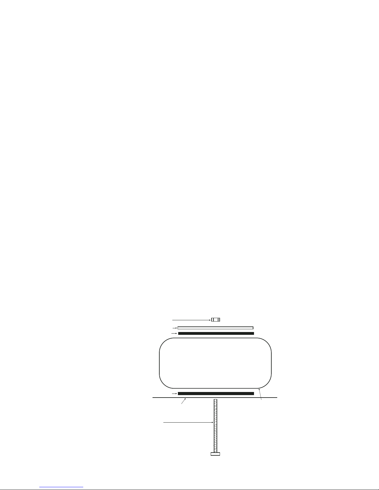
When fitting PCB Pins they should be pressed into place with a
hot soldering iron (make sure the pins get hot before pushing
them fully home) and then soldered on each side of the board.
Where possible it is good practice to fit components with the
lowest profile (eg links or low value resistors) first and those
with the highest profile (eg large capacitors) last.
FIT THE VALVE BASES.
The valve bases should be fitted to the component side of the
PCB. Make sure that you solder the legs on both sides of the PCB
to give a secure mechanical (as well as electrical) joint.
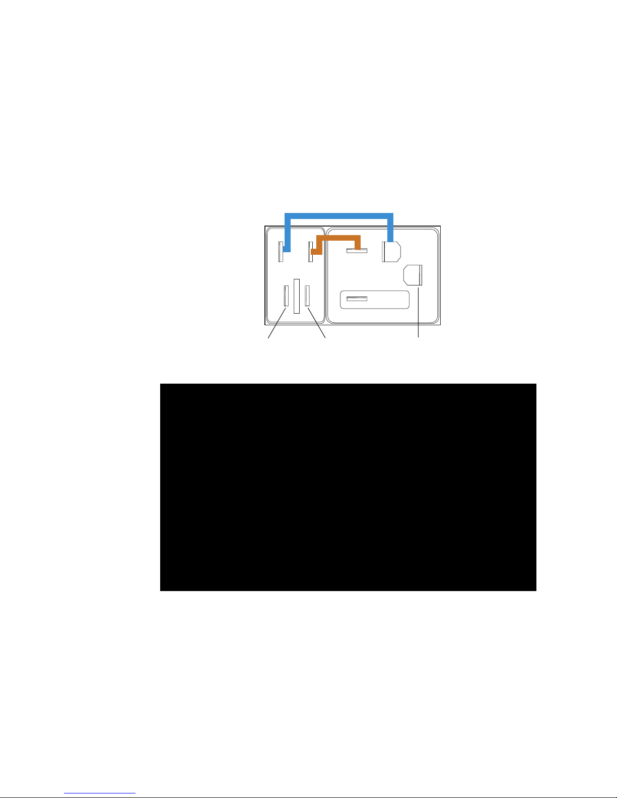
FIT THE PCB PINS.
We have highlighted the PCB pin positions in colour on the
photograph overleaf so that you can find them easily (the
picture also shows the soldering points for the heater links,
highlighted in white). Solder the pins so that they project on
the component side of the board in the following positions:
POWER SUPPLY: HTR CT Y, HTR-OR, HTR+OR, BLACK, RED (5 pins,
highlighted in light blue in Fig. 7)
OUTPUT TRANSFORMER PRIMARIES / TERTIARIES: OPTXL BLACK, RED HT L,
FBL, FBLG, OPTXR BLACK, HT R RED, FBR, FBRG (8 pins, highlighted
in red in Fig. 7)
OUTPUT TRANSFORMER SECONDARIES: B3, P1, B4, P2, B2, P3, B1, P4
for both channels (16 pins, highlighted in yellow in Fig. 7)
INPUTS: IPL, IPLG, IPR, IPRG (4 pins, highlighted in dark blue
in Fig. 7)
OUTPUTS: OPL, OPLG, OPR, OPRG (4 pins, highlighted in green in
Fig. 7)
LED: LED-, LED+(2 pins, highlighted in orange in Fig. 7)
Fig. 10
Figs.
7/10
WDHD3S Kit Assembly Instructions
7
POPULATING THE PCB
The PCB is double -sided. In this manual the side with the
component “legends”(indicating where the components should be
sited) printed on it is referenced as the component side and the
other side as the solder side.
Where possible it is advisable to solder the legs of the
components to both sides of the PCB. The holes in the PCB are
“plated -through”meaning that soldering both sides is not
strictly necessary. It is nonetheless good practice to ensure a
good joint and to provide mechanical security -the board is
subject to repeated heating and cooling which can produce stress
and cracked joints.
If you ever need to “drill out”any holes in order to fit
upgraded components it is ESSENTIAL to solder both sides of the
joint.
When fitting PCB Pins they should be pressed into place with a
hot soldering iron (make sure the pins get hot before pushing
them fully home) and then soldered on each side of the board.
Where possible it is good practice to fit components with the
lowest profile (eg links or low value resistors) first and those
with the highest profile (eg large capacitors) last.
FIT THE VALVE BASES.
The valve bases should be fitted to the component side of the
PCB. Make sure that you solder the legs on both sides of the PCB
to give a secure mechanical (as well as electrical) joint.
FIT THE PCB PINS.
We have highlighted the PCB pin positions in colour on the
photograph overleaf so that you can find them easily (the
picture also shows the soldering points for the heater links,
highlighted in white). Solder the pins so that they project on
the component side of the board in the following positions:
POWER SUPPLY: HTR CT Y, HTR-OR, HTR+OR, BLACK, RED (5 pins,
highlighted in light blue in Fig. 7)
OUTPUT TRANSFORMER PRIMARIES / TERTIARIES: OPTXL BLACK, RED HT L,
FBL, FBLG, OPTXR BLACK, HT R RED, FBR, FBRG (8 pins, highlighted
in red in Fig. 7)
OUTPUT TRANSFORMER SECONDARIES: B3, P1, B4, P2, B2, P3, B1, P4
for both channels (16 pins, highlighted in yellow in Fig. 7)
INPUTS: IPL, IPLG, IPR, IPRG (4 pins, highlighted in dark blue
in Fig. 7)
OUTPUTS: OPL, OPLG, OPR, OPRG (4 pins, highlighted in green in
Fig. 7)
LED: LED-, LED+(2 pins, highlighted in orange in Fig. 7)
Fig. 10
Figs.
7/10