World Video Sales MicroImage Video Systems VMU250 User manual

Video Caliper
Operation Manual
For Models
VMU250
VMU350
VMU850
MicroImage Video Systems
division of World Video Sales Co., Inc.
PO Box 331
Boyertown, PA 19512
Phone 610-754-6800
Fax 610-754-9766
mivs.com
Rev 1.00 12-05-2022

2
CONTENTS
UNPACKING ................................................................................................................................ 5
CONNECTIONS ........................................................................................................................... 5
Power Supply ........................................................................................................................... 5
Video Input ............................................................................................................................... 5
Video Output ............................................................................................................................ 5
Other Connections ................................................................................................................. 6
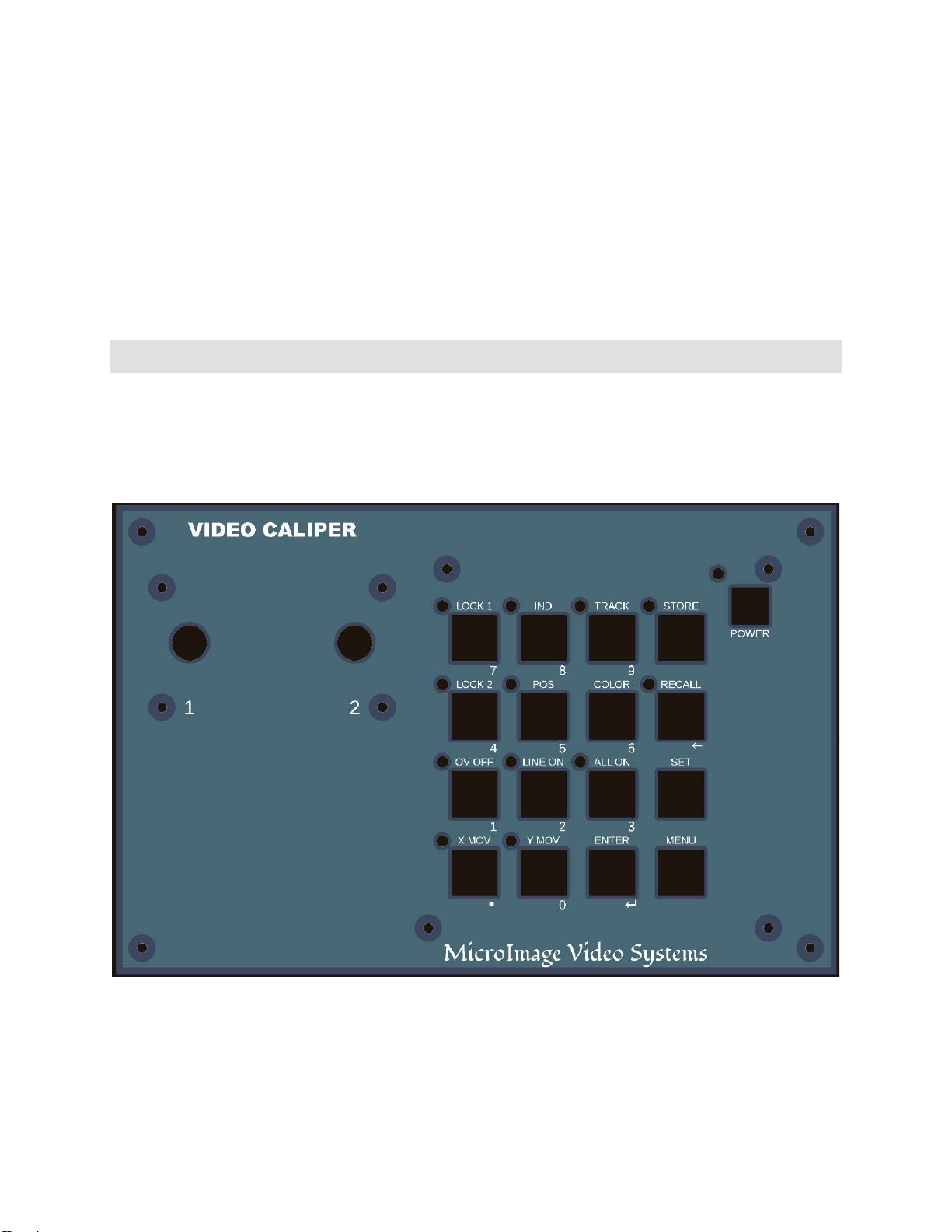
CONTROLS & INDICATORS ..................................................................................................... 6
Unlike previous VMU units, the VMU250, VMU350 and VMU850 have multiple
switches which share functions. Notably, the numeric keypad functions are only
available when the menus are active. ................................................................................ 6
Power Switch ............................................................................................................................ 6
Position Control 1 ................................................................................................................... 7
Position Control 2 ................................................................................................................... 7
Lock Switch 1 & Lock Switch 2 .............................................................................................. 7
Ind & Track Switches .............................................................................................................. 7
POS (Position) Switch ............................................................................................................. 7
OV Off, Line On, All On Display Switches ........................................................................... 7
X & Y Switches .......................................................................................................................... 8
COLOR Switch .......................................................................................................................... 8
MENU Switch ............................................................................................................................ 8
SET Switch ................................................................................................................................. 8
ENTER ........................................................................................................................................ 9
STORE ........................................................................................................................................ 9
RECALL ....................................................................................................................................... 9
MENUS .......................................................................................................................................... 9
Overview ................................................................................................................................... 9
Lines ......................................................................................................................................... 10
1. Vertical 1 Style ....................................................................................................... 10
2. Vertical 2 Style ....................................................................................................... 11
3. Horizontal 1 Style ................................................................................................. 11
4. Horizontal 2 Style ................................................................................................. 11
5. Line Width ............................................................................................................... 11
6. Lock Overrides ...................................................................................................... 12
7. Line/Box Mode ...................................................................................................... 12
8. Track Switch Mode ............................................................................................... 12
9. Line Movement Options .................................................................................... 12
Readout ................................................................................................................................... 13

3
1. Readout Display ...................................................................................................... 13
2. Character Color ....................................................................................................... 13
3. Character Background .......................................................................................... 13
4. Row/Column ............................................................................................................ 14
5. Digits of Precision ................................................................................................... 14
6. Ratio Precision ......................................................................................................... 14
Display ..................................................................................................................................... 14
Clock ......................................................................................................................................... 14
Remote Options .................................................................................................................... 15
System Options ..................................................................................................................... 15
Password Options ................................................................................................................. 15
1. Password Mode ............................................................................................................ 15
2. Protect Now ................................................................................................................... 16
3. Change Password ......................................................................................................... 16
CALIBRATION SET .................................................................................................................... 18
Overview ................................................................................................................................. 18
Set Scale Using X Axis ........................................................................................................... 18
Set Scale Using Y Axis ........................................................................................................... 18
Clear Scale .............................................................................................................................. 19
Select Unit ............................................................................................................................... 19
Define Custom Unit .............................................................................................................. 19
Aspect Ratio Compensation ............................................................................................... 19
MEMORIES ................................................................................................................................. 21
Overview ................................................................................................................................. 21
Memory Store ........................................................................................................................ 21
Memory Recall ....................................................................................................................... 22
PASSWORD PROTECTION ...................................................................................................... 22
Overview ................................................................................................................................. 22
OPERATION ............................................................................................................................... 22
Overview ................................................................................................................................. 22
Calibration .............................................................................................................................. 22
Setting the Scale .................................................................................................................... 22
Adding a unit of measure.................................................................................................... 23
Saving the current configuration....................................................................................... 23
Memory Store ........................................................................................................................ 23
Memory Recall ....................................................................................................................... 24
FACTORY DEFAULTS ............................................................................................................... 24
Overview ................................................................................................................................. 24

4
DIFFERENCES FROM PREVIOUS MODELS ......................................................................... 25
SPECIFICATIONS ....................................................................................................................... 26
WARRANTY ................................................................................................................................ 28
RETURNS .................................................................................................................................... 28

5
UNPACKING
The Video Caliper system includes the following components:
VMU250, VMU350 or VMU850 Video Caliper Unit
12 volt power supply
This operation manual
Please inspect all items carefully and report damaged or missing items to your dealer or
MicroImage Video Systems. Do not power up any damaged unit.
CONNECTIONS
Power Supply
The Video Caliper ships with a standard 12VDC power supply that is suitable for use in North
America. Internationally sold units may include a “world” power supply with multiple plug
adapeters.
Connect the power supply to a suitable power receptacle/outlet which meets the appropriate
ratings on the power supply. You may need to install a different plug adapter for
receptacles/outlets other than those used in the USA.
All Video Caliper units may be optionally powered from a clean source of external +12VDC
(+10 to +20V) negative ground power. Contact MicroImage Video Systems for additional
information.
The unit may take several seconds to power up and initialize.
Video Input
A video source must be connected to the Video Caliper for it to function properly. The unit
will automatically detect the input signal and adjust accordingly. It typically takes less than
one second for a valid signal to be detected and the VMU to set itself accordingly.
The VMU259 and VMU350 Video Caliper may be connected to a composite or B&W video
source (via the Video Input BNC connector).
The VMU850 Video Caliper Video Input may be connected to an HDMI or DVI video source
signal.
Video Output
Connect a suitable output cable from the appropriate Video Out connector to a monitor or
other display device. Make sure that the monitor (or other device) is correctly set to view that
type of video signal. Note that some cameras may output both High Definition and Standard

6
Definition video, and may produce SD video with non-standard vertical to horizontal ratios.
VMU850 note: The VMU850 is compatible with most video cameras that produce a true and
properly formatted video signal. Some cameras do not provide a true quality signal and may
work intermittently or not at all.
Other Connections
If you have a custom option installed which requires an external connection, please see the
supplement to this user guide for additional information.
CONTROLS & INDICATORS
Unlike previous VMU units, the VMU250, VMU350 and VMU850 have multiple switches which
share functions. Notably, the numeric keypad functions are only available when the menus
are active.
Above: Layout of the VMU Control Panel.
Power Switch
The power switch is located in the upper right corner of the front panel. Pressing it once
turns the unit on, pressing it again turns the unit off. When off, the unit draws minimal power.
All VMU units will remember their settings when the power is turned off. More information

7
is provided later in this text. The unit will also remember the power switch setting when
power is removed. If the power switch was on when power is disconnected, it will turn on
again when power is restored to the unit.
Position Control 1
This rotary control will move the left or top cursor (depending on the setting of the X/Y switch)
or it will move both (same axis) cursors together if the track function is enabled. This control
is also used to select the field which is being edited in other menus.
Position Control 2
This rotary control will move the right or bottom cursor (depending on the setting of the X/Y
switch). If track mode is on, it will adjust the spread between the two (same axis) lines. This
control is also used to alter the value of the field being edited in other menus.
Lock Switch 1 & Lock Switch 2
Enabling the lock function will cause the related rotary position control to have no effect
while the corresponding Lock is on (indicated by the RED lamp above the switch), in order to
prevent accidental or unauthorized movement of a control. Lock functions are remembered
independently for the X and Y axes. A Lock override can be set in the menu system to lock a
control regardless of the switch setting (its functional status will be indicated by the light).
Ind & Track Switches
Enabling the tracking function (yellow track (indicator on) will cause the left position control
to move both lines of the same axis together, keeping the spacing constant. The right control
will adjust the spacing between the lines. Depending on the settings in the Track Switch
Mode menu, when active, the right control will either move the second line relative to the
first (Track Mode) or move both lines in opposite directions from a mid-point between them
(Mirror Mode). When IND (Independent mode) is pressed, the tracking function is disabled
(Green IND indicator now illuminated), the two controls will move the lines fully
independently.
POS (Position) Switch
The position set function allows the user to relocate the numeric display. Pressing the POS
switch (indicator on) will activate the position set function for the numeric display. When the
position function is enabled (the orange indicator above it is illuminated), turn the left (#1)
rotary control to change the horizontal position and the right (#2) rotary control to change
the vertical position. Press the POS switch again when finished to disable the position set
function. Note that many other functions are disabled while position set is on.
OV Off, Line On, All On Display Switches
OV OFF - Pressing this switch will turn off all overlay graphics allowing an unimpeded view of
the source image. When the OV OFF is set, a blue indicator above it will illuminate. When the
display is off, many switches and the controls are inactive to prevent accidental changes.

8
LINE ON - Pressing this switch will display only the lines (menus are also allowed). A Magenta
indicator will illuminate when this mode is enabled.
ALL ON - Pressing this switch will enable the lines and coordinate box to be displayed as well
as all menus and addition graphics. A white indicator will illuminate to signal that this mode
is active.
X & Y Switches
The X and Y switches select between X and Y axis movement with the controls. Pressing the
X switch will allow the vertical lines to move horizontally with the controls and is indicated by
a green indicator. The Y switch will allow the horizontal lines to be moved vertically and has
a yellow indicator above the switch to signal this mode is being used.
COLOR Switch
For the VMU250 & VMU350, this switch selects whether the lines are displayed as black, gray,
or white. This switch does not affect the shades used by the numeric display or menu system.
The COLOR switch will repeatedly cycle through the three different shades.
For the VMU850, pressing this switch will bring up a color menu and allow the color of each
line to be selected.
MENU Switch
Pressing the MENU switch places the unit in the menu mode allowing the user to set his or
her preferences. The exact menus are covered in a later chapter in this manual. Pressing
the Menu switch again will exit Menu mode.
If the password protection is turned on, you may have to enter a password before using this
function.
SET Switch
Pressing SET will allow the user to calibrate the unit and also set the unit of measure.
Operation is through simple menus. Pressing the Set switch again will exit the Set menu.
If the password protection is turned on, you may have to enter a password before using this
function.
BACKSPACE KEY
When a menu requires editing, the backspace key will be active. It’s functionality is shared
with the RECALL Switch. Pressing the backspace button will allow you to edit the numeric
calibration or the password as it is being entered. Backspace deletes the character last
entered.
0 thru 9 and . (decimal point)

9
These keys are shared with various other functions and the letting for the numeric kepad is
to the bottom right of the button it relates to. These keys are used to enter the calibration
reference, enter the password and to navigate the menu systems. They are used in a way
similar to a calculator. Note that the 2, 4, 6 and 8 keys are also used as a four directional
cursor array when changing coordinate colors or editing the time and custom unit of
measure settings.
ENTER
Completes the entry of a calibration setting or password, or completes a menu operation.
New time settings, passwords, or user memory settings are not saved until after the Enter
key is pressed. The unit may take several seconds until it saves the data, although the unit
should otherwise return to normal operation almost instantly.
STORE
Pressing the STORE key will illuminate the indicator next to it and allow you to save the unit’s
current settings into one of 9 user memory locations. The memory function will save most
of the settings of the unit, allowing easy access to multiple calibrations. See the section on
Memories later in this manual.
If the password protection is turned on, you may have to enter a password before using this
function. Note: The operation of the above function has changed from the previous model.
RECALL
Pressing the RECALL key will blink the indicator next to it and restore the settings previously
saved into one of the 9 user memory locations. See the section on Memories later in this
manual.
MENUS
Overview
The VMU series of Video Calipers are designed for ease of use along with the ability to be
highly customized to meet many demands. Commonly used functions are easily changed
with front panel switches while less used functions can be changed through the menu
systems. This section will describe the various menus and how they work. For the
calibration set menus and units of measure, please see the next section.
Note that the exact menus present may vary depending on the model.
If you have the Password Protection enabled, you may need to enter a password before you
can enter the menu. See the section on Password Protection for additional information.
The menu system is divided into a hierarchy, or tree structure. Each branch has several
related menus that can be changed. The main or top menu is the first one you see after
pressing the MENU button. You then choose one of the categories and press the number

10
key relating to that menu. This will bring up another menu where you press the numeric key
of choice and so on. Pressing the 0 (zero) key will exit each menu back up to the previous
menu.
SYSTEM OPTIONS
This is the main system menu. Items with a dark arrow following the item name activate a
sub-menu with more choices.
Each menu option will be described below:
Lines
The Line Options menu allows you to set the properties of the horizontal and vertical
measuring lines.
1. Vertical 1 Style
SYSTEM OPTIONS
1. Lines
2. Readout
3. Display
4. Clock
5. Password
6. Remote
7. System
0. Exit
Press a number key to select
Press Menu key to exit
LINE OPTIONS
1. Vertical 1 Style
2. Vertical 2 Style
3. Horizontal 1 Style
4. Horizontal 2 Style
5. Line Width
6. Lock Overrides
7. Line/Box Mode
8. Tracking Mode
9. Line Movement Options
0. Back
Press a number key to select
Press Menu key to exit

11
This item activates a submenu to set the X1 (left) vertical line to solid, serrated or
off. Each line may be set individually.
1. Off will disable the selected line.
2. Solid will display the selected line as a solid line.
3-6. These choices will display the selected line as a series of dashes and spaces
as shown.
1. This will return to the Line Options menu.
2. Vertical 2 Style
This item activates a submenu to set the X2 (right) vertical line to solid, serrated
or off. Each line may be set individually. The sub-menu functions in the same
manner as the Vertical 1 Style menu.
3. Horizontal 1 Style
This item activates a submenu to set the Y1 (top) horizontal line to solid, serrated
or off. Each line may be set individually. The sub-menu functions in the same
manner as the Vertical 1 Style menu.
4. Horizontal 2 Style
This item activates a submenu to set the Y2 (bottom) horizontal line to solid,
serrated or off. Each line may be set individually. The sub-menu functions in the
same manner as the Vertical 1 Style menu.
5. Line Width
VERTICAL 1 STYLE
1. Off
2. Solid
3. --- --- --- ---
4. -- -- -- --
5. ------ ------
6. ---- ----
0. Back
Press a number key to select
Press Menu key to exit

12
Line size can be set to three different thicknesses. Both X and Y axis are affected
by this setting. When the line size is set thicker, measuring resolution will be
lower due to video system restrictions and display capabilities. Thin lines may
also cause a slight increase in apparent flicker on some monitors due to
limitations of the NTSC/PAL video system on the VMU250 and VMU350 standard
definition video units.
6. Lock Overrides
Allows you to enable lock overrides for each line. If these are set to On, the line
will remain locked regardless of how the front panel lock switch is set (lock
indicators will light). If these are set to Off, the functionality of the controls may
be toggled by the lock switches.
7. Line/Box Mode
This will set whether lines or a box will be displayed. In Line mode, the lines are
full screen length and height. In Box mode, the lines are truncated at their
intersections, forming a box.
8. Track Switch Mode
The Tracking menu determines the function of the Tracking switch for both the
vertical and horizontal line pairs. In “Off” (independent) mode, the controls will
move the two lines of the pair (either vertical or horizontal) independently. The
front panel Tracking switch will have no effect.
In Tracking mode, the first control will move both lines of the pair, while the
second control will move the second line relative to the first. The front panel
Tracking switch will toggle between independent and Tracking modes.
In Mirror mode, the first control will move both lines, while the second control
will move both lines in opposite directions relative to a point mid-way between
them. The front panel switch will toggle between independent and Mirror
modes.
In Both modes, the front panel switch will cycle between independent, Tracking,
and Mirror modes. The movement of the lines will depend on which mode is
selected by the switch.
9. Line Movement Options
This opens a sub-menu to adjust the direction of the vertical control and to
adjust the fast/slow movement rates of the cursors. Turning the controls quickly
will result in rapid jumps of the lines, while slower movement of the controls will
lead to less movement of the lines over the same rotation of the control.

13
2. Normal Speed Set – adjusts the sensitivity of the controls when the position
controls are turned quickly. This allows the user to quickly put the lines close to
where they need to be with less turns of the rotary controls. The higher the
number chosen, the slower the lines will move.
3. Precision Speed Set – reduces the rate of line movement when the controls
are turned at a rate below the threshold. This allows the lines to be moved with
a high degree of precision, and placed exactly on target.
4. Slow/Fast Threshold Set – This sets the speed threshold between fast and slow
control movement rates. A low threshold will provide rapid movement rates at
even a modest turn rate, while a high threshold will require a rapid spin of the
controls to access the higher movement speed of the lines.
0. Back
Returns you to the System Menu. Generally, the Back option returns you to the
previous higher-level menu. Selecting this again while in the System menu will
exit the menu system.
Readout
1. Readout Display
You can choose whether or not to display the numeric values for X, Y, and
diagonal measurements, or X/Y and Y/X Ratios. Any combination can be
displayed. See further information about displaying or suppressing the date and
time. Ratio functions are available on units with a serial number of 31032 and
later.
2. Character Color
Sets the foreground (character) shade of the alpha-numeric digits but does not
affect the line shade (see the B/W switch to switch between line shades). The Set
Character Color menu allows you to choose any grayscale shade on the chart by
either rotating the controls or by pressing the 8, 4, 6, and 2 keys as a cursor
control pad. The new selection will be indicated with a check mark. If the alpha-
numeric display box is near the edges of the screen, it is possible to see the
shades “in context” as you browse through them. The “present” selection will be
indicated with the letter “P”. The Enter key will change the Present selection to
the shade indicated by the check mark. Pressing the “0” key without pressing the
Enter key will exit the menu without changing the Present shade.
3. Character Background

14
Sets the background shade of the alpha-numeric digits but does not affect the
line shade (see the B/W switch to switch between line shades). The Set
Character Background menu allows you to choose any shade on the chart by
either rotating the controls or by pressing the 8, 4, 6, and 2 keys as a cursor
control pad. The new selection will be indicated with a check mark. If the alpha-
numeric display box is near the edges of the screen, it is possible to see the
shades “in context” as you browse through them. The “present” selection will be
indicated with the letter “P”. The Enter key will change the Present selection to
the shade indicated by the check mark. Pressing the “0” key without pressing the
Enter key will exit the menu without changing the Present shade.
4. Row/Column
Chooses whether the X, Y, Diagonal dimensions, and Ratios are displayed in a
row or column format. Depending on the number of digits displayed, and the
number or leading or trailing zeros required by the calibration setting, (see
Precision Digits), it may not be possible to format the display on a single line.
5. Digits of Precision
Allows the user to choose the precision of the measurement display. For
readability, the display precision can be reduced to only the amount of
information that is really needed for the application, freeing up more screen
space for the image. The precision can be set from 2 to 8 significant digits, with 4
being the factory default. Depending on the number of leading or trailing zeros
required, the actual displayed digits may vary. Examples: 215, 0.0000215, or
21500, each with three “significant” digits, but different numbers of “displayed”
digits.
6. Ratio Precision
Allows the user to choose the precision of the Ratio display past the decimal
point. For readability, the display precision can be reduced to only the amount of
information that is really needed for the application, freeing up more screen
space for the image. The precision can be set from 0 to 6 digits, with 3 being the
factory default. Not applicable on serial numbers of 310031 or before.
Display
This allows the user to set additional display items, including the positions of non-measuring
reference lines and the display of optional gauge data.
Clock
A clock circuit provides both time and date information. This can optionally be displayed
below the measurement data, or instead of it. The Clock sub-menu provides options for
displaying and setting the time and date.

15
1. Display Clock
The Clock Display sub-menu allows the user to display or hide either the date or time,
and either display them on the same row, or in a column with one above the other.
2. Clock Settings
The Clock Settings sub-menu allows the user to individually toggle the Seconds
display on or off, display time in either 12 or 24 hour modes, show or not show
AM/PM, show or hide the day of the week, and to display the month either as in
numerical form or as a letter abbreviation.
3. Date Layout Settings
The Date Layout Settings sub-menu allows the user to select the order of day,
month, and year. This can be in the US format of Month/Day/Year (JAN 1, 2015) or
in the commonly used European format of Day/Month/Year (1 JAN 2015), with the
year either displayed as a two-digit (15) or four-digit (2015) number.
4. Set Clock
The Set Time/Date sub-menu allows the user to set the time and date. Rotating the
left control will select which field to edit, and rotating the right control will alter the
value of the selected field. The four number keys 8, 4, 6, and 2 can also be used as a
cursor keypad to change both field and value: 4 (left) and 6 (right) change the field,
while 8 (up) and 2 (down) increment or decrement the value. Pressing the Enter key
will update the unit to the new time. Pressing the Menu key will exit the sub-menu
without changing the time.
0. Back
Pressing the “0” key will return you to the System Options Menu.
Remote Options
The remote options are only used when the factory optional remote interface is ordered
and installed in the unit. This interface comes with a separate interface operation manual.
System Options
System Properties This menu shows the product name, the firmware revision and
code base as well as the MicroImage copyright for the code.
There is also a link to the MicroImage Web site as well.
Password Options
1. Password Mode

16
There are five (5) different modes of operation for the password system. They are as
follows:
1. Off - This will allow all menus and the store function to be accessed
without having to enter a password. This is the default mode from the
factory.
2. Enable at Menu Exit - Each time a menu is exited, the password
protection will be re-enabled so the next time menu, set or store buttons are
pressed, the password will have to be entered again.
3. Enable at Power Off - Once the correct password is entered, all functions
will be accessible without having to re-enter the password until the power is
turned off to the unit, which will place it back in protected mode. This will
require the password to be entered to access the menus and store function
when the unit is turned on again.
4. Menu Exit + 1 min - Approximately one minute (1.2 minutes for PAL) after
exiting a menu, the password requirement will automatically become active,
requiring you to enter the password again the next time Menu, Set or Store
are pressed. The time is counted from the last time a menu is used. If you
used the menu every 45 seconds, the password would never be required.
This provides enough time for a reasonably familiar user to switch between
menu and calibration functions without having to re-enter the password
each time.
5. Menu Exit + 5 min - Approximately five minutes (6 minutes for PAL) after
exiting a menu, the password requirement will automatically become active,
requiring you to enter the password again the next time Menu, Set or Store
are pressed. The time is counted from the last time a menu is used. If you
used the menu every 4 minutes, the password would never be required.
2. Protect Now
This immediately reinstates the password requirement if it has been enabled in the
Password Mode menu, and would be the same as turning the unit off and back on. Use
this when you make changes and need to have the unit password protected before
leaving the location.
3. Change Password
Allows you to change the password to any number up to 8 digits. You need to enter
the number, press Enter, then enter the number again. The backspace key can be used
to correct entry. Passwords do not have to be all eight digits, use the number of digits
you feel necessary to secure the unit. In fact, if no number is entered in either box,
then that becomes the password, just pressing enter will get you past the password

17
screen but that is not recommended for security. Both entry boxes must match to
complete the function. If they do not, a screen will inform you that they don t match
and ask you to press the Enter key to try again. There is no cancel function, turn the
unit off to cancel this command. When both input numbers match, a screen will be
display that indicates the password has been changed and asks you to press the Enter
key to continue.

18
CALIBRATION SET
Overview
The SET menu is similar in operation to the MAIN MENU, however the SET menu is used to
set the calibration for the unit and the unit of measure. See the section about operation
(setting the scale) for additional information on using the SET menu. Below, each menu is
described in detail. Calibration only needs to be set for one axis to calibrate all directions.
If you have the Password System enabled, you may need to enter a password before you
can enter the set menu. See the section on Password Protection for additional information.
Set Scale Using X Axis
This will set the calibration using the horizontal (left to right) axis, or the distance between
two vertical (up-down) lines. It will accept any number, up to eight digits between
0.0000001 and 99999999 for the calibration.
Note that measuring is much more precise when setting the calibration on the X axis, as
opposed to the Y axis, due to the higher horizontal resolution of the video standard.
Calibration is also more precise when the distance between the two lines is as wide as
possible during calibration.
Set Scale Using Y Axis
This will set the calibration Using the vertical (top to bottom) axis, or the distance between
two horizontal (left-right) lines. Enter any number, up to eight digits between 0.0000001 and
99999999 for the calibration.
Note that measuring is much more precise when setting the calibration on the X axis. Y axis
calibration is provided for those places where X axis calibration is impractical. Calibration is
also more precise when the distance between the two lines is as wide as possible during
calibration.
Scale and Unit Parameters
1. Set Scale Using X Axis
2. Set Scale Using Y Axis
3. Clear Scale
4. Select Unit
5. Define Custom Unit
0 Exit this Menu
Press number for selection

19
Clear Scale
Clear scale will set the calibration to a value of 1.0000 per pixel regardless of the line
positions. This can be handy for making absolute position measurements with the lines and
measuring in pixels.
Select Unit
You will initially be provided with four options as follows:
1. Off The unit of measure display is disabled.
2. Metric Units A selection of commonly used Metric units are available in this
menu. Press the number corresponding to the unit to be
displayed.
3. English Units A selection of commonly used English units are available in this
menu. Press the number corresponding to the unit to be
displayed.
4. Custom This will display all the user defined units. Units must have
been previously defined (see menu item 5, Define Custom Unit
below). The unit of measure is the same for all three
measurements.
Define Custom Unit
Up to eight different user defined units of measure can be entered. Each can be up
to four characters long. Once defined here, they will be available in the Select Unit
menu described above. To set a unit, press the appropriate number for the memory
location where you want to save the unit. Either press the left and right cursor keys
(#4 and #8) or rotate the left control to select the character to change. Next, either
press the up and down keys (#2 and #8) or rotate the right control to change the
character. A wide variety of alpha-numeric characters and punctuation symbols are
provided. Press the ENTER key when complete.
Note: This will not select the Custom Unit for use. The unit can be selected from the
Custom option in the Select Unit sub-menu.
Aspect Ratio Compensation
Some cameras produce both High Definition and Standard Definition video
outputs. Many of these cameras alter the normal vertical to horizontal
aspect ratio of the video signal, requiring recalibration each time the axis
changes between vertical and horizontal measurements.
The Aspect Ratio Compensation function allows the user to correct for the
difference in vertical and horizontal measurements by placing a known

20
round or square object in the field of view and placing the cursors on all four
sides of it. The VMU will then modify all measurements to adjust for the
aspect ratio.
1. Auto 4:3
The default standard definition aspect ratio.
2. Widescreen Compensation
NOTE: This function is not available on the VMU850 High Definition Video
Caliper.
New Correction Method
1. With the unit turned on, operating, and connected to the camera it would
normally use, place a perfectly square or perfectly round item in the field of
view. For the most accurate results, it should be at least half of the screen
height in size, preferably 70-80%. The item should look round or square, if
not, see the note at the end of this paper.
2. Next, move the four measurement cursors to the edges of the square or
round item as precisely as possible. Use the X/Y key to go between the H and
V directions of movement.
3. When finished, press the SET button.
4. Select menu item 6 (Widescreen Correction) by pressing the 6 button.
5. Press number 2 (Widescreen Correction Set).
6. If you agree with the text on the screen that appears, press 5 to continue
the process and make the correction. Press SET to clear the menu.
That’s it, the correction will now be applied until changed. To confirm it is
correct, both the X and Y values in the numeric display should be the same.
From this point forward, you only need to calibrate the unit on a single axis
and it will know how to display properly for the opposite axis and diagonals.
If the Square or Circle is Distorted with a Wide Screen Display
When connecting a standard definition signal to a wide-screen display, you
will likely have to set the display mode. Circles and squares should look
correct, or very close to it, but it might require some monitor settings to be
changed.
This manual suits for next models
2
Table of contents