Harris Legacy 99-1300-0 User manual

Broadcast
Console
Operations
&
Technical
Manual
HARRIS 75-51
Revision B • 1/03
99-1300-0 (14-input mainframe)
99-1300-1 (22-input mainframe)
99-1300-2 (30-input mainframe)
BroadcastCommunicationsDivision
www.broadcast.harris.com

Revision B • 1/03
HARRIS CORPORATION
ii

Revision B • 1/03
HARRIS CORPORATION
iii
Contents
Safety Instructions ......................................... iv
Hazard/Warning Label Identification............. iv
Manual Revisions............................................ v
1- GENERAL INFORMATION
Product Overview ........................................1-1
Specifications ...............................................1-4
Warranty......................................................1-6
2- INSTALLATION
Console Installation......................................2-2
Mainframe Configuration ........................2-2
Connector Access ....................................2-3
Power Supply..........................................2-4
Grounding and Shielding ........................2-4
Installing Backup Batteries .....................2-4
Setting the Clock .....................................2-5
EventTimer ............................................2-6
Meter Setup ............................................2-6
Cabling andWiring ......................................2-7
Required Cables andWire .......................2-7
Wire Preparation ....................................2-7
CrimpTool Operation..............................2-8
Audio Connections .......................................2-9
Unbalanced Connections .......................2-10
Digital Clock Reference ..............................2-11
Logic Connections......................................2-11
Universal Input Logic Interface .............2-12
Setting DIP Switches.............................2-13
Quick Guides for Each Module...................2-16
Logic Connection Examples .......................2-50
Microphone Logic .................................2-50
Basic Peripheral Logic ..........................2-52
Complex Peripheral Logic.....................2-54
3- OPERATION
Module Overview .........................................3-1
Meter Panel Overview ..................................3-1
Microphone Preamplifier Module .................3-2
Universal Input Module................................3-3
Telco/Codec Module.....................................3-5
Remote Line Selector (RLS) Module ..........3-10
Meter Switcher Module ..............................3-11
Control Room Module................................3-12
Studio Module ...........................................3-13
Output 1 Module........................................3-14
Output 2 Module........................................3-14
Meter Panel................................................3-15
4- MAINTENANCE
Parts and Repair Services.............................4-1
Parts Ordering and Repair Information ...4-1
Spare and Replacement Parts..................4-2
Tool and Installation Kits........................4-3
Module Servicing .........................................4-3
Fader Servicing .......................................4-4
Clock and EventTimer .................................4-5
Backup Batteries..........................................4-5
Power Supply...............................................4-5
GeneralTroubleshootingTips .......................4-6
5- ACCESSORIES
Furniture and Cabinetry...............................5-1
Furniture-Mounted Panels............................5-1
Peripheral Panels .........................................5-2
Mic Remote Panels.......................................5-2
Headphone Distribution Amp ......................5-2
LogicWiring Diagrams & Cables ..................5-2
INDEX

Revision B • 1/03
HARRIS CORPORATION
iv
1. Read All Instructions. Read all safety and operating
instructions before operating the product.
2. Retain All Instructions. Retainallsafetyandoperating
instructions for future reference.
3. Heed AllWarnings.Youmustadheretoall warnings
on the product and those listed in the operating
instructions.
4. Follow All Instructions. Follow all operating and
product usage instructions.
5. Heat. This product must be situated away from any
heat sources such as radiators, heat registers,stoves,
or other products (including power amplifiers) that
produce heat.
6. Ventilation. Slots and openings in the product are
providedforventilation.Theyensurereliableoperation
of the product and keep it from overheating.Do not
block or cover these openings during operation.Do
not place this product into a rack unless proper
ventilation is provided and the manufacturer’s
recommended installation procedures arefollowed.
7. Water and Moisture. Do not use this product near
water such as a bathtub, wash bowl, kitchen sink, or
laundry tub,in a wet basement,or near a swimming
pool or the like.
8. Attachments. Do not use any attachments not
recommended by the product manufacturer as they
may cause hazards.
9. Power Sources.Youmustoperatethisproductusing
the type of power source indicated on the marking
label and in the installation instructions.If you are not
sure of the type of power supplied to your facility,
consult your local power company.
10. Grounding and Polarization. This product is
equippedwithapolarizedACplugwithintegralsafety
ground pin. Do not defeat the safety ground in any
manner.
11. Power Cord Protection.Powersupplycordsmustbe
routed so that they are not likely to be walked on nor
pinched by items placed upon or against them. Pay
particular attention to the cords at AC wall plugs and
convenience receptacles,and at the point where the
cord plugs into the product.
12. Lightning. For added protection for this product,
unplug it from the AC wall outlet during a lightning
storm or when it is left unattended and unused for
long periods of time.This will prevent damage to the
product due to lightning and power line surges.
13. Overloading. Do not overload AC wall outlets,
extensioncords,orintegralconvenienceoutletsasthis
can result in a fire or electric shock hazard.
14. Object and Liquid Entry. Never push objects of any
kind into this product through openings as they may
touch dangerous voltage points or short out parts,
whichcouldresultina fireorelectricshock.Neverspill
liquid of any kind on the product.
15. Accessories. Donotplacethis product onanunstable
cart, stand, tripod,bracket, or table.The product may
fall,causingseriousinjurytoachildoradultandserious
damagetotheproduct.Anymountingofthe product
must follow manufacturer’s installation instructions.
Safety Instructions16. Product and Cart Combination.Movethisproduct
with care. Quick stops, excessive force, and uneven
surfaces may cause the product and the cart
combination to overturn.
17. Servicing. Refer all servicing to qualified servicing
personnel.
18. Damage Requiring Service. Unplug this product
fromthewallACoutletandreferservicingtoqualified
service personnel under the following conditions:
a. When the AC cord or plug is damaged.
b. Ifliquidhas beenspilled orobjects havefallen into
the product.
c. If theproduct has been exposed to rain or water.
d. Iftheproductdoesnotoperatenormally(following
operating instructions).
e. If the product has been dropped or damaged in
any way.
f. When the product exhibits a distinct change in
performance.This indicates a need for service.
19. Replacement Parts. When replacement parts are
required, be sure the service technician has used
replacement parts specified by the manufacturer or
thathavethesamecharacteristicsastheoriginalparts.
Unauthorized substitutions may result in fire,electric
shock,or other hazards.
20. Safety Check.Uponcompletionof anyrepairsto this
product,ask the service technician to performsafety
checks to determine that the product is in proper
operating condition.
21. Cleaning. Do not use liquid or aerosol cleaners.Use
only a damp cloth for cleaning.
WARNING—This equipment generates,uses,and can radiate radio frequencyenergy.If not installed andused inaccordancewith the instructionsin this
manual it may cause interference to radio communications. It has been tested and found to comply with the limits for a Class A computing device
(pursuanttoSubpartJ ofPart 15FCCRules),which aredesignedto provide reasonableprotectionagainst such interferencewhenoperatedin acommer-
cial environment. Operation of this equipment in a residential area is likely to cause interference,in which case the user, at his own expense, will be
required to take whatever measures may be required to correct the interference.
Hazard/Warning Label Identification
TheLightning FlashWith
Arrowhead symbol,within an
equilateral triangle,alerts the user to
the presence of uninsulated
dangerous voltage within the
product’s enclosure that may be of
sufficient magnitude to constitute a
risk of electric shock.
TheExclamation Point symbol,
within an equilateral triangle,alerts the
user to the presence of important
operating and maintenance (servicing)
instructions in product literature and
instruction manuals.
RISK OF ELECTRIC SHOCK
DO NOT OPEN
CAUTION
WARNING:SHOCK HAZARD - DO NOT OPEN
AVIS:RISQUE DE CHOC ELECTRIQUE - NE PAS OUVRIR
CAUTION:TO REDUCETHE RISK OF ELECTRIC SHOCK DO NOT
REMOVE ANY COVER OR PANEL.NO USER SERVICEABLE PARTS
INSIDE.REFER SERVICING TO QUALIFIED SERVICE PERSONNEL.
WARNING: TO REDUCETHE RISK OF FIRE OR ELECTRIC SHOCK,
DO NOT EXPOSETHE POWER SUPPLY OR CONSOLETO RAIN OR
MOISTURE.

Revision B • 1/03
HARRIS CORPORATION
v
This page provides a quick reference of the
current document pages and their revision level. If
you receive a revision to this document from Harris,
replace the old manual pages with the new ones and
discardtheold pages.Replacethispagewiththenew
Manual Revisions page.
Revision Affected pages Comments
A All pages 2/02 First Release
B All pages 1/03 corrected various
installation & operation
descriptions. Added
accessory product
information.Condensed
manual page count.
Manual Revisions

Revision B • 1/03
HARRIS CORPORATION
vi

Revision B • 1/03
HARRIS CORPORATION
1-1
1
Thank you for joining the growing ranks of
broadcasters employing Harris Corporation prod-
ucts designed by Pacific Research & Engineering.
HarrisCorporationsuppliesaudioproductsandsys-
temstothe world’sleading broadcastfacilities.Our
mission is to provide the finest quality products,
systems,documentation,and after-salesupport.We
invitecommentsandsuggestionsforimprovements
to this documentation and to all of our services.
The Legacy is a very sophisticated console with
anextensiverangeof features contained in a com-
pact design.To obtain maximum benefit from the
console’s capabilities, read the
Installation
and
Operation
chapters prior to product installation.
PRODUCT OVERVIEW
Each Legacy console ships with the following
modules installed in the mainframe:
• Microphone Preamplifier module (one
5-inputMic Preamp PCAstandard,second
5-input Mic Preamp PCA optional)
• Universal Input modules (as ordered)
• Telco/Codec modules (up to 4,as ordered)
• Remote Line Selector (RLS) modules
(as ordered)
• Meter Switcher module (1 standard)
• Control Room module (1 standard)
• Studio module (1 optional)
• Output modules (2 standard)
Blank panels cover unused module positions.
The Legacy’s motherboard and module area is
completely contained within a sheet metal and
extruded aluminum chassis for strength and RFI
immunity.The meter panel is hinged at the rear,
closingovertheupperpart of themodulesto cover
theaudioandlogicconnectorsandtheLogicSetup
switches.The chassis bottom is open beneath the
meter panel for easy cable access.
ModuleDescriptions
Microphone Preamplifier Module
This module (PRE99-1151-2) can hold ten
high-performancepreamplifiers(fivearestandard
with an additional five optional).Each has a gain
trim control under a security cover. Phantom
power(+48VDC) is selectableforeachinput.Each
Mic Preamp boosts its mic-level inputs (from -65
dBu to -30 dBu) to a line level (+4 dBu),low-im-
pedance, balanced output for connection directly
to a Universal Input module or to outboard mic
processingequipment.
One module with a 5-input Mic Preamp PCA is
standard; a second optional 5-input PCA may be
installed.An additional 5-input Mic Preamplifier
module (PRE99-1151-2) or a 10-input Mic
Preamplifiermodule (PRE99-1151-1) maybein-
stalledintothe slot directly tothe right of thestan-
dard Mic Preamplifier module.
General
Information

Revision B • 1/03
HARRIS CORPORATION
1-2
1 General Information
EachTelco module includes the following con-
trolsorfeatures:channelon/offcontrol,faderlevel
control,cue control, modeselection with pan/bal-
ance control, Send control, record and monitor
controls, and output/Foldback selection to four
program buses and one off-line bus.Logic I/O is
available for logic wiring to/from the hybrid or
codec.
Remote Line Selector (RLS)
Module
This module (PRE99-1323) features twobanks
of eight selection buttons to independently route
the eight input signals to the two outputs. The
module switch either analog or digital signals,as
set by a DIP switch on the module.
Meter Switcher Module
This module (PRE99-1317) is located to the
right of the input module area.It provides control
of the digital timer and contains the meter source
selector buttons and the signal drivers for all the
meterdisplays.
The timer control section features stop, start,
hold, and reset controls, as well as whether the
modules automatically reset the timer.
Control Room Module
This module (PRE99-1318) contains the moni-
tor source selection and control facilities for the
console operator,and a co-host and a guest in the
control room.The module has parallel logic con-
trol (via a 14-pin connector) which provides ex-
ternal monitor dimming or muting, and warning
light control.The module includes four external
monitor inputs and six monitor and headphone
outputs.The outputs can simultaneously monitor
any combination of up to six analog sources (four
external inputs and Telco Record and Monitor)
andtwo digital sources (fourprograms and Send).
The Control Roommodulefeaturesmonitorand
headphonefader-levelcontrols,monitor-modecon-
Universal Analog/Digital Input
Module
The Universal Input modules (PRE99-1315)
feature two inputs (A and B), each of which can
acceptanalog or digital signals.Setup switcheson
the module set the source for each input. They
also set the source level (for analog signals) or the
attenuation amount (for digital signals). Each in-
put has its own fully independent parallel logic
control connector for remote control of the mod-
uleand/ormodulecontrol of the associatedsource
equipment.
Each Universal Input module includes the fol-
lowing controls or features: A/B input selection,
channel on/off control, fader level control, cue
control,mode selection with pan/balance control,
Sendcontrol,and output bus selectiontofour pro-
gram buses and one off-line bus.
Two 24-pin logic connectors connect logic wir-
ing to/from external control panels or peripher-
als. DIP switches set logic and module function
options for the A and B inputs.
Telco/Codec Input Module
Up to fourTelco/Codec (Telco) modules can be
installed into any of the input module slots on the
mainframe.The optionalTelco module (PRE99-
1316) has a single audio input (analog or digital)
from a remote send and receive device (like a tele-
phonehybrid,satellitetransceiver,ISDN interface,
or other stereo or mono Codec).
Eachmodulefeaturesmanual or automatic con-
trol of the Foldback signal returned to the hybrid
or codec.The Foldback signal for eachTelco mod-
ulecan be manually setto anyprogram oroff-line
bus.The Foldback signal can also follow theTelco
module’s on/off status when the Auto-Foldback
function is active. The Auto-Foldback function
automatically switches the feed to the caller be-
tween the off-line mix and the assigned bus with
the highest priority.For more information,see the
Telco Operation section on pages 3-7 to 3-9.

Revision B • 1/03
HARRIS CORPORATION
1-3
1 General Information
trol, cue and talkback level controls, and head-
phoneAuto-Cue select.
Studio Module
The optional Studio module (PRE99-1319) is
installedto the right of theControl Room module.
It provides a monitor and talkback-level control
for one studio or voice booth.The monitor source
can be any combination of 11 sources (four exter-
nalinputs,four programs,Send,andTelco Record
and Monitor) simultaneously.
The Studio module has a 14-pin parallel logic
connector for external dimming or muting of the
studio monitor speakers and control of a studio
warning light interface.Controls also provide the
ability to talk to or from a studio and an external
location.
Output Modules
Two Output modules ship standard with the
Legacy.
The Output 1 module (PRE99-1320) contains
the digital-to-analog converters and mix matrices
for creating mix-minus foldbacks to support up
to fourTelco/Codec modules. It also contains in-
dividually mixed outputs forTelco/Codec record-
ing.There is a mix-minus output for eachTelco/
Codecmodule.Digitaland analog outputs are pro-
vided for the mix-minus and recorder feed out-
puts. For digital outputs, sample rates of 48 kHz
and44.1 kHzare supported.The mix-minus ana-
log outputs are fixed at +4 dBu.This module fea-
tures output sample rate selectors for digital out-
puts and a gain trim control for the analogTelco
record mix output.
The Output 2 module (PRE99-1321) contains
the AES digital output drivers, digital-to-analog
converters,andanalog line amplifiersfor the Send
output and the four program outputs.The digital
output sample rate is 48 kHz.An output sample
rate of 44.1 kHz can be selected for the program
1 and 2 auxiliary outputs, the program 3 and 4
outputs,and the Send output. Gain trim controls
for the analog outputs are also provided.
PowerSupply
The separately packaged rack-mount power
supply assembly (PRE99-1202) uses keyed con-
nectorsto supply asingle +48 voltsDCto the con-
sole mainframe. There are two connectors from
thepowersupplyassemblytotheconsole:onecon-
nector supplies DC power and the other supplies
electrical signal information to the console.The
power supply module has an on/off switch and
an LED indicator on the front panel.The power
supplyis fully regulated and protectedagainst ex-
cessive current by internal fuses and electronic
safeguards.

Revision B • 1/03
HARRIS CORPORATION
1-4
1 General Information
SPECIFICATIONS
The specifications for the Legacy are signifi-
cantly more complete, and the related test condi-
tions are more defined, than those usually shown
for consoles in this class.Be sure to follow the test
conditions and measure in the units as stated.
The specifications arefor a fullyloaded Legacy-
30 input mainframe.
Test Conditions:
Specificationsare forthe basicsignal paths,per
channel, with >1k ohm loads connected to the
analog main outputs.
0 dBu corresponds to an amplitude of 0.775
volts RMS regardlessof the circuit impedance.This
is equivalent to 0 dBm measured into a 600 ohm
circuit for convenient level measurement with
meterscalibratedfor600ohm circuits.Noisespeci-
fications are based upon a 22 kHz measurement
bandwidth.The use of a meter with 30 kHz band-
width will result in a noise measurement increase
of approximately 1.7 dB.
Total Harmonic Distortion (THD+N) is mea-
sured at a +18 dBu output level using 1 kHz or a
swept signal with a 22 kHz low-pass filter.
FSD = Full Scale Digital, +24 dBu
Microphone Preamplifiers
Source Impedance: 150 ohms
Input Impedance: 5 k ohms minimum, balanced
Input Level Range: Adjustable, -65 to -30 dBu
Input Headroom: >20 dB above nominal input
Output Level: +4 dBu, nominal
Analog Line Inputs
Input Impedance: >40 k ohms, balanced
Input Level Range: Selectable; -10 dBv, +4 dBu,
+6 dBu, +8 dBu
Input Headroom: 20 dB above nominal input
Analog Main Outputs
Output Source Impedance: <3 ohms balanced
Output Load Impedance: 1 k ohms minimum
Nominal Output Levels: Program,Send,Telco/Codec
Mix-Minus,TelcoRecordMixFeed:+4 dBu,ad-
justable between +3 dBu and +9 dBu
Maximum Output Levels: Program, Send, Telco/
Codec Mix-Minus, Telco Record Mix Feed:
+24 dBu; +28 dBu with 100k output load im-
pedance and nominal output level adjusted to
+8 dBu
Digital Inputs and Outputs
Reference Level: +4 dBu (-20 dB FSD)
Digital I/O:Through digital input and digital Pro-
gram, Send,Telco/Codec Mix-Minus outputs
Signal Format: AES-3, S/PDIF (input only)
AES-3 Input Compliance:
24-bit sample rate conver-
sion available, individually switch selectable
AES-3 Output Compliance:
24-bit
Digital Reference:
Crystal (internal) or AES-3 (ex-
ternal) at 48 kHz ±100 ppm
Internal Sample Rate:
48 kHz
Output Sample Rates: Program 1 and 2 Main out-
puts 48 kHz;Program 1 and 2 Aux,Program 3
and4,Send,Telco/Codec Mix-Minus,andTelco
Record Mix outputs 48 kHz or 44.1 kHz, indi-
vidually switch selectable
Processing Resolution:
24-bit fixed with extended
precision accumulators
Conversions:
A/D 24-bit, Delta-Sigma, 128x
oversampling on all digital inputs; D/A 24-bit,
Delta-Sigma,128x oversampling
Latency:
<1.6 ms, mic in to monitor out

Revision B • 1/03
HARRIS CORPORATION
1-5
1 General Information
Monitor Outputs
Output Source Impedance: <3 ohms, balanced
Output Load Impedance: 1 k ohms minimum
Output Level: +4 dBu nominal,+24dBu maximum
Frequency Response
Microphone or Line Input to Program or Send Output:
+0 dB/-0.5 dB, 20 Hz to 20 kHz
Dynamic Range
Analog Input to Analog Output: 105 dB referenced to
FSD, 108 dB“A”weighted to FSD
Analog Input to Digital Output: 109 dB referenced to
FSD
Digital Input to Analog Output: 107 dB referenced to
FSD, 110 dB“A”weighted to FSD
Digital Input to Digital Output: 138 dB
Equivalent Input Noise
Microphone Preamp:-127 dBu, 150 ohm source
Total Harmonic Distortion + Noise
Mic Pre Input to Mic Pre Output: <0.005%, 20 Hz to
20 kHz, -38 dBu input, +18 dBu output, 100k
ohm load, 22 kHz filter bandwidth
Analog Input to Analog Output: <0.003% at 1 kHz,
+18 dBu input, +18 dBu output, 100 k ohm
load, 22 kHz filter bandwidth
Digital Input to Digital Output:
<0.00016%,20 Hzto
20 kHz, -20 db FSD input, -20 db FSD output,
20 kHz filter bandwidth
Digital Input to Analog Output:
<0.003% at 1 kHz,
-6 db FSD input, +18 dBu output, 100 k ohm
load, 22 kHz filter bandwidth
Crosstalk Isolation
Program-to-Program or to-Program or to-Send:
>95dB,
20 Hz to 20 kHz
A Input to B Input, B Input to A Input:
>110 dB,20 Hz
to 20 kHz
Stereo Separation
Analog Program Outputs:
>86 dB,20 Hz to 20 kHz
Console Power Requirements
Fully configured Legacy-14:185 watts at 115/230
VAC, ±12%, 50/60 Hz
Fully configured Legacy-22:250 watts at 115/230
VAC, ±12%, 50/60 Hz
Fully configured Legacy-30
:
285 watts at 115/230
VAC, ±12%, 50/60 Hz
Power SupplyVoltage
Console power: +48VDC at 8.34 Amp, redundant
operation optional
Power Supply Ground
Rack-mount power supply frame: grounded through
AC cord
Power Supply Connection
AC input: IEC power cord
DC output: two keyed multi-pin connectors
Dimensions
Legacy-14:9.75
"
x 41.13
"
x 33.38
"
(H,W, D)
Legacy-22:9.75
"
x 54.44
"
x 33.38
"
(H,W, D)
Legacy-30:9.75
"
x 67.24
"
x 33.38
"
(H,W, D)
Power Supply (Rack-mount power supply frame):
3.5
"
(2 RU) x 19.0
"
x 16.0
"
(H,W, D)
HarrisCorporation reserves the right to change
specifications without notice or obligation.

Revision B • 1/03
HARRIS CORPORATION
1-6
1 General Information
E) This Warranty is void for equipment which
has been subject to abuse, improper installa-
tion, improper operation, improper or omit-
ted maintenance, alteration, accident, negli-
gence(in use,storage, transportation,or han-
dling), operation not in accordance with
Seller’s operation and service instructions, or
operation outside of the environmental con-
ditions specified by Seller.
F) ThisWarranty is the only warranty made by
Seller, and is in lieu of all other warranties,
includingmerchantabilityandfitnessforapar-
ticularpurpose,whetherexpressed or implied,
except as to title and to the expressed specifi-
cations contained in this manual.Seller’s sole
liability for any equipment failure or any
breach of thisWarranty is as set forth in sub-
paragraph A) above; Seller shall not be liable
or responsible for any business loss or inter-
ruption,orotherconsequentialdamagesofany
nature whatsoever, resulting from any equip-
ment failure or breach of this warranty.
WARRANTY
The Legacy digital console carries a
manufacturer’s warranty which is subject to the
following guidelines and limitations:
A) Except as expressly excluded herein, Harris
Corporation (“Seller”) warrants equipment of
its own manufacture against faulty workman-
ship or the use of defective materials for a pe-
riod of one (1) year from date of shipment to
Buyer.The liability oftheSeller under thisWar-
rantyis limited to replacing,repairing,or issu-
ing credit (at the Seller’s discretion) for any
equipment, provided that Seller is promptly
notified in writing within five (5) days upon
discoveryofsuchdefects byBuyer,and Seller’s
examination of such equipment shall disclose
to its satisfaction that such defects existed at
the time shipment was originally made by
Seller, and Buyer returns the defective equip-
ment to Seller’s place of business in Mason,
Ohio, packaging and transportation prepaid,
with return packaging and transport guaran-
teed.
B) Equipment furnished by Seller, but manufac-
tured by another, shall be warranted only to
theextentprovided bythe othermanufacturer.
C) Thermal filament devices, such as fuses, are
expressly excluded from this warranty.
D) The warranty period on equipment or parts
repaired or replaced under warranty shall ex-
pire upon the expiration date of the original
warranty.

2
Revision B • 1/03
HARRIS CORPORATION
2-1
The Legacy mainframe is designed to
“drop into” a cutout (shown below) in the studio
furniture countertop. A minimum of 14 inches
(355.7 mm) of vertical clearance above the
countertop is required to fully open the meter
panel.The rear 2.5 inches (63.5 mm) of the main-
frame is open so wiring can be easily dressed up
throughthe mainframe to the module connectors,
which are hidden below the meter panel.
The Legacy console shipment consists of:
• The 14-, 22-, or 30-input mainframe with the
standard modules (Microphone Preamp,Meter
Switcher,ControlRoom,and Outputs) installed,
along with the other modules ordered (Univer-
salInput,Telco/Codec,RLS,Studio),and blank
panels to cover any unused positions.
• The rack-mount power supply assembly.
• The LegacyToolkit (3AA batteries,AMPMOD
IV crimp tool and contact removal tool, hex
driver,and module removal tool).
• Audio and Logic connector kit. The kit con-
tains all theAMP MOD IV connector housings
and receptacle contacts typically needed for
installation.
Installation
Console FrontView Console SideView,with dimensions (inches & [mm])
5.75"
[146.1]
11.79"
[299.5]
4.00"
[101.6]
0.75"
[19.1]
33.38"
[847.9]
4.00"
[101.6]
2.48"
[63.0]
14.00
"
[355.6]
2.50"
[63.5]
COUNTERTOP
1234567890123456789012345678901212345678
1
23456789012345678901234567890121234567
8
1
23456789012345678901234567890121234567
8
1
23456789012345678901234567890121234567
8
1
23456789012345678901234567890121234567
8
1
23456789012345678901234567890121234567
8
1
23456789012345678901234567890121234567
8
1
23456789012345678901234567890121234567
8
1
23456789012345678901234567890121234567
8
1
23456789012345678901234567890121234567
8
1
23456789012345678901234567890121234567
8
1
23456789012345678901234567890121234567
8
1
23456789012345678901234567890121234567
8
1
23456789012345678901234567890121234567
8
1
23456789012345678901234567890121234567
8
1
23456789012345678901234567890121234567
8
1
23456789012345678901234567890121234567
8
1
23456789012345678901234567890121234567
8
1
23456789012345678901234567890121234567
8
1
23456789012345678901234567890121234567
8
1234567890123456789012345678901212345678
CONSOLE CUTOUT
(for recessed installations)
C
30.5"
[774.9]
DimensionTable
Mainframe A B C
Legacy-14 41.13"[1044.7] 38.94" [989.1] 39.20" [995.7]
Legacy-22 54.44"[1383.2] 51.70"[1313.5] 52.00"[1321.2]
Legacy-30 67.24"[1708.4] 64.50"[1638.8] 64.75"[1645.1]
Millimeter dimensions in brackets. All dimensional tolerances are
+¼" [6.35], -0" [0.0]. Typical front setback is 12" [304.8]. Allow
14" [355.7] clearance above the countertop.
Revision B • 1/03
HARRIS CORPORATION
2-2
2 Installation
MAINFRAME CONFIGURATION
The Legacy design positions the input modules
inthe physical center of the mainframe.This gives
the operator equal reach to peripheral equipment
located to the either side of the console.
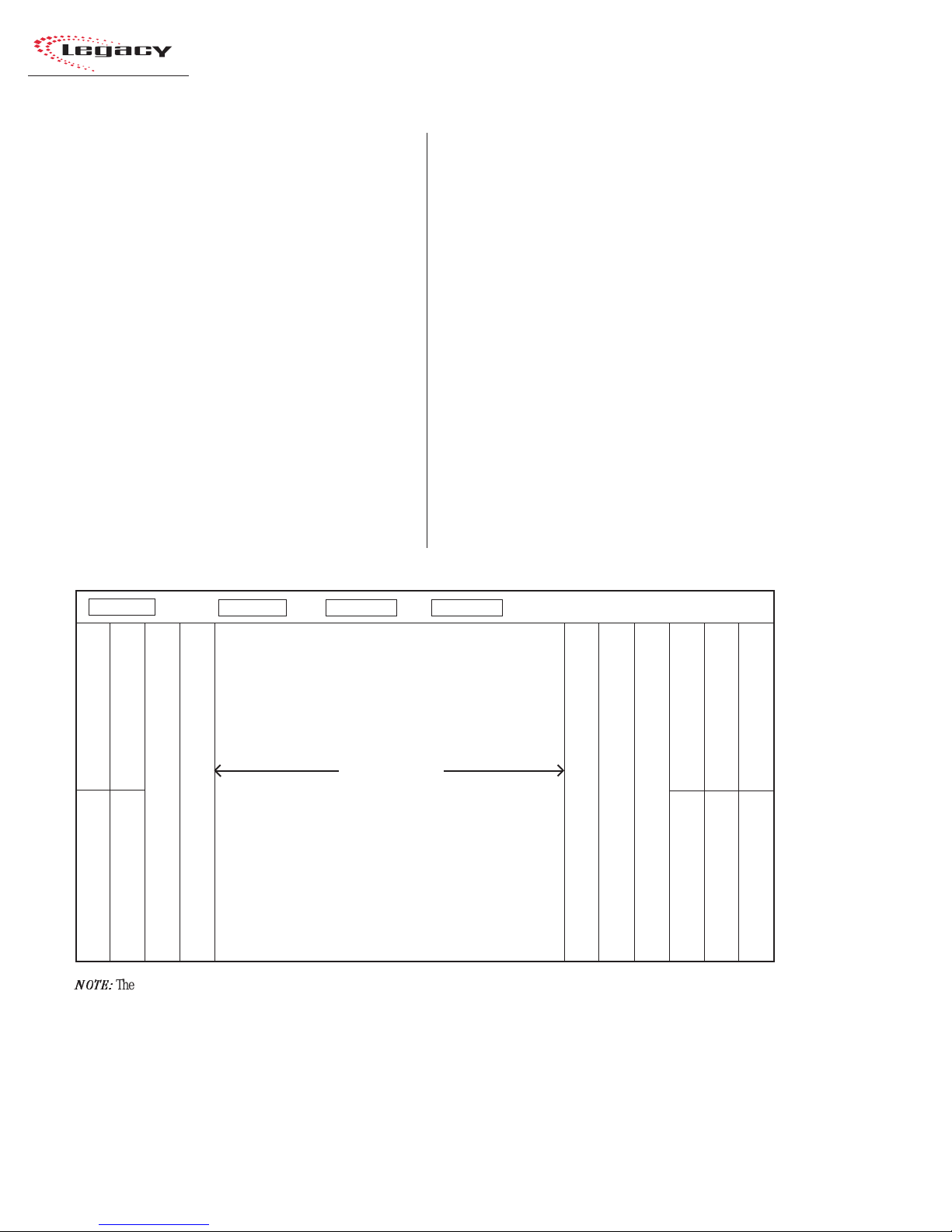
ModulePlacement
The 14, 22, or 30 input module positions can
have any combination or order of the following
modules installed: Universal Input,Telco/Codec
(fourmaximum),andRemoteLineSelector(RLS).
The remaining console positionsarefixed.TheMic
Preamplifier module(s), Meter Switcher module,
Control Room module, optional Studio module,
and the two Output modules must be positioned
as shown in the illustration below.
Console Installation
To simplify console installation,logic cable wir-
ingdiagramsfor specific peripheralequipmentare
available from the Harris Technical Services de-
partment. See page 4-1 for contact information.
INSTALLATION NOTE: Do not locate the con-
solenear intense electromagnetic hum fields,such
as those produced by large power transformers
and by audio amplifiers that use inexpensive
power transformers operating in or near satura-
tion.Strongelectromagneticfields mayimpair the
performanceoftheLegacyandneighboring equip-
ment.Audio cables mustalso berouted to achieve
maximum practical distance from all AC power
mains wiring.
Reserved position (covered by a 25" Blank panel)
Reserved position (covered by a 25" Blank panel)
Meter Switcher (standard)
Control Room (standard)
Studio (optional) 25”blank panel (standard)
Legacy Mainframe,Module Configuration
Mic Preamp (standard)
Output 1 (standard)
Output 2 (standard)
NOTE:
The number of input module positions matches the console model number (e.g., Legacy-22 has 22 input positions). There are
two DSP cards in the Legacy-14, three in the Legacy-22, and four in the Legacy-30.
The areas covered by the five 12.25" Blank Panels can be used for mounting Harris BMXdigital Accessory Panels or custom remote
control panels. Since the Harris BMXdigital Accessory Panels are 6" long, a PRE99-1100 Divider Kit (for mounting up to four
Accessory Panels in place of two 12.25" Blank Panels), or a PRE99-1101 Divider Kit (for mounting up to six Accessory Panels in place
of three 12.25" Blank Panels) is required. Typically, the PRE99-1100 Divider Kit is installed in place of the Blank Panels on the left
end of the console and the PRE99-1101 is installed in place of the Blank Panels on the right end of the console. 6" Blank Panels
(PRE99-1714-3) cover unused Accessory Panel positions.
Input modules
The input module positions are
filled with any combination or
number of Universal Input and
Remote Line Selector modules,and
up to fourTelco/Codec modules.
Unused positions are covered with
25" Blank Panels.
12.25" Blank Panel (standard)
12.25" Blank Panel (standard)
12.25" Blank Panel (standard)
12.25" Blank Panel (standard)
12.25" Blank Panel (standard)
DSP Card 1 (Master) DSP Card 2 DSP Card 3* DSP Card 4* * (number of DSPs present
set by the frame size)
Mic Preamp 2 (optional)
12.5”blank panel (standard)
12.5”blankpanel
(standard)

2 Installation
Revision B • 1/03
HARRIS CORPORATION
2-3
MeterPanel
The meter panel contains three horizontal bar-
graphmeters.Twoofthemetersprovideindividual
level monitoring for the Program 1 and 2 out-
puts.The third meter is used to monitor the level
of Cue, Program 3 or 4, any external input, the
Send output, or the Telco Record output, as se-
lected on the Meter Switcher module.The level at
which the peak indicator (PK) comes on, as well
asthe meter displaymode (peakhold or non-peak
hold),may be set for each meter via DIP switches
on each meter display board.
The meter panel also contains a slaveable 12/
24-hour digital clock (HH:MM:SS) and an event
timer (MM:SS:T) that can be controlled manu-
ally, through buttons on the Meter Switcher mod-
ule, or automatically through module On com-
mands.
For additional information on the meter panel,
see pages 3-15 and 3-16.
CONNECTOR ACCESS
All module connectors are hidden below the
meterpanel in normal operation.Themeter panel
connects to the rear of the console by hinges.To
access the connectors, open the meter panel by
lifting it up and rotating it toward the rear of the
console until it stops.
Caution: Make sure that the panel is open all
the way so that it does not accidentally fall shut.
To facilitate initial wiring, the meter panel can
be removed from the mainframe chassis.
To removethe meterpanel from themainframe:
1Open the meter panel fully and unplug the
meterpowercable(attached to the rearpanel)
and the two cables (meter signals and talk-
back mic) from the Meter Switcher module.
2With another person holdingthemeter panel,
remove the screws and bushings that attach
each gas spring to the meter panel. Lay the
gas springs on the mainframe while working.
3Unlatchthehinges bymovingtherelease pins
to their unlocked positions and lift the meter
panel up and off the mainframe.
Toreinstall the meterpanel,alignthe two halves
of the hinges, then release the pins out of their
unlockedpositions.
Reattach each gas spring to the meter panel by
inserting a screw through the gas spring and the
bushing.
Main Meters
(Program 1 and 2)
Clock Event
Timer
Aux Meter
(Meter Switcher:Displays
Cue,Program 3 or 4,Send,
or Telco Record)
Legacy Meter Panel

Revision B • 1/03
HARRIS CORPORATION
2-4
2 Installation
GROUNDING ANDSHIELDING
The broadcast facility’s technical ground can
be connected to the mainframe chassis using the
threaded insert on the rear of the console (shown
in the Power Connections drawing on this page).
Use a 10-32 screw and crimp lug to terminate the
facility’s technical ground wire.
Connect the cable shields at both the console
and the peripheral end when all system compo-
nents share a common ground potential and are
usingisolated groundAC outlets tied individually
back to the main technical ground.
If isolated ground AC outlets are not available,
connect the cable shields at the console end only.
The shields should be floated (left unconnected)
at the peripheral device end. Ensure the periph-
eral devices connect to a clean ground through
their power cords, or through separate ground
wires to the facility’s technical ground.
POWER SUPPLY GROUNDING
NOTE: The Power Supply chassis
connects to the AC mains safety or
“U”ground wire.
AUDIOGROUNDNOISES: Buzz pickup is gener-
ally electrostatic—such as capacitive coupling
between an audio line and a power line.To avoid
audio ground noises, do not route audio lines in
the same wireway as an AC power line.
INSTALLINGBACKUPBATTERIES
ThreeAA rechargeable NiCad batteriesare sup-
pliedinthe 76-2001Tool Kit.They supplya“Keep
Alive” voltage to hold each module’s logic state
duringmomentary power outages.They mount in
a battery clip located below the three 12" blank
panels on the right end of the console.
To install the backup batteries:
1Removethethreeblankpanelslocatedinfront
of the Output modules.
Threaded
Insert for
10-32
screw
Power
Supply
Status
48VDC
Power
Meter
Panel
Power
Power Connections —
Console Mainframe, Rear Panel
POWERSUPPLY
The power supply assembly is rack mounted (it
requires 2 RU or 3.5" [88.9 mm] of rack space)
within the console cabinetry, below and to the left
or right of the supporting countertop.The Legacy
Power Supply must be installed so that the 30
foot power supply cable supplied with the Power
Supply is not under any tension when routed
through the cabinet and connected to the
mainframe’s rear panel connectors.
ConnectingthePowerSupply
The power supply cable has two connectors:
• A 5-pin connector to supply 48 volt DC
power to the console.
• A 4-pin connector to supply power supply
statusinformation (Imminent Power Loss)
to the console.
Both connectors must be attached to the back
of the Legacy and to the power supply.
DC GROUNDING NOTE:
Do not
connect
the audio or logic supply
ground wiring to the chassis of the
power supply.
AC GROUNDING NOTE: Do not
defeat the safety ground in any way.
Doing so may provide a potentially
dangerous condition to the operator.

2 Installation
Revision B • 1/03
HARRIS CORPORATION
2-5
Master clocks are available from:
ESE
142 Sierra St.
El Segundo,CA 90245.
Telephone: 310.322.2136
www.ese-web.com
-+-
+- +
Output 1
Output 2
Blank
Middle 12.25" Blank Panel
removed to show the
battery clip
12.25" Blank panel
12.25" Blank panel
Backup Battery Installation
12345678901234567890123
1
234567890123456789012
3
1
234567890123456789012
3
1
234567890123456789012
3
1
234567890123456789012
3
1
234567890123456789012
3
1
234567890123456789012
3
1
234567890123456789012
3
1
234567890123456789012
3
1
234567890123456789012
3
1
234567890123456789012
3
1
234567890123456789012
3
1
234567890123456789012
3
1
234567890123456789012
3
1
234567890123456789012
3
1
234567890123456789012
3
1
234567890123456789012
3
1
234567890123456789012
3
1
234567890123456789012
3
1
234567890123456789012
3
1
234567890123456789012
3
1
234567890123456789012
3
1
234567890123456789012
3
1
234567890123456789012
3
1
234567890123456789012
3
1
234567890123456789012
3
1
234567890123456789012
3
1
234567890123456789012
3
1
234567890123456789012
3
1
234567890123456789012
3
1
234567890123456789012
3
12345678901234567890123
Clock Option Switches (DS1)
Clock circuit board DIP switch.
Factory default settings are DOWN.
12 3 45
SWITCH DOWN
12-hour
TC89
ESE Disabled
(Autonomous)
Unused
Unused
Clock PCA
SWITCH UP
24-hour
TC90
ESE Enabled
(Slaved)
Unused
Unused
2Install the batteries into the battery clip,
observing the correct polarity marked on the
battery clip, as shown below.
Note: Replace batteries yearly to ensure con-
tinuous backup protection. Because this device is
optimized for continuous slow charge operation,
usePanasonicP-50AAHbatteries(ortheirequiva-
lent).To prolong battery life,remove the batteries
when the console will be powered down for an
extended period.
SETTINGTHE CLOCK
The digital time-of-day clock can operate in au-
tonomous or slave modes. When used autono-
mously (the factory preset), a temperature-con-
trolled quartz crystal oscillator controls the clock
timing.In slave mode,clock timing comes from a
TC89-orTC90-compatible ESE master clock ref-
erence signal.
The operating mode (autonomous or ESE slave),
the type of ESE signal (TC89 orTC90), and the
type of clock time desired (12-hour or 24-hour
format)are set using DIP switchDS1on the clock
PCA. DS1 is on the right rear edge of the circuit
board.
To access the clock PCA,open the meter panel.
The clock PCA is mounted behind the clock dis-
play on the meter panel.
Withthe clock set toautonomous mode,it must
be set after power-up. There are three clock set
buttons on the bottom left front of the clock PCA.
• Usethe right button (Fast) toscroll bymin-
utes at a time.
• Use the middle button (Slow) to scroll by
seconds at a time.
• Use the left button (Hold) to synchronize
the console clock to an external time refer-
ence by setting the clock ahead of the
Clock Circuit Board,left front edge
Setting the Clock
Hold Slow Fast

Revision B • 1/03
HARRIS CORPORATION
2-6
2 Installation
METERSETUP
The level at which theblue peakindicators turn
on, as well as the meter display mode (peak hold
ornon-peak hold), is set separately for eachmeter
usingDIPswitchesontheedgeofeach meter PCA.
Toaccess the meter DIP switches,openthemeter
panel by lifting it up and rotating it toward the
rearof the console until itstops.Each meter’s DIP
switchesare locatedon theunderside of the meter
panel, directly below the right end of each meter.
externaltimereference,then press and hold
the HOLD button to freeze the time.When
theexternaltime reference reachesthe time
ontheLegacy clock,release the HOLDbut-
ton to start the clock.
When an ESE time-code signal is connected to
theBNC connector onthe clock circuitboard, and
slave mode is selected (DS1-3 is set UP),the clock
does not require setting. If the ESE time-code sig-
nal fails, the clock automatically defaults to its
internal crystal reference oscillator, flashing the
display colons to indicate the loss of time-code.
EVENTTIMER
The event timer displays time in minutes, sec-
onds and tenths of seconds.The only timer option
setting is whether to display the tenths of seconds
digit as the timer runs. DS1-1 (a DIP switch on
the timer circuit board, located behind the timer
display),setswhether the tenths are shownor not.
In the UP position, the tenths of seconds are dis-
played.Inthe DOWNposition,the factory default,
the tenths do not display while the timer runs.
Note that the tenths of seconds are always shown
when the timer is in the Stop or Hold mode.
EventTimer Option Switches (DS1)
12345678901234567890123456
1
234567890123456789012345
6
1
234567890123456789012345
6
1
234567890123456789012345
6
1
234567890123456789012345
6
1
234567890123456789012345
6
1
234567890123456789012345
6
1
234567890123456789012345
6
1
234567890123456789012345
6
1
234567890123456789012345
6
1
234567890123456789012345
6
1
234567890123456789012345
6
1
234567890123456789012345
6
1
234567890123456789012345
6
1
234567890123456789012345
6
1
234567890123456789012345
6
1
234567890123456789012345
6
1
234567890123456789012345
6
1
234567890123456789012345
6
1
234567890123456789012345
6
1
234567890123456789012345
6
1
234567890123456789012345
6
1
234567890123456789012345
6
1
234567890123456789012345
6
1
234567890123456789012345
6
1
234567890123456789012345
6
1
234567890123456789012345
6
1
234567890123456789012345
6
1
234567890123456789012345
6
1
234567890123456789012345
6
1
234567890123456789012345
6
12345678901234567890123456
Timer circuit board DIP switch.
Factory default settings are DOWN.
12345
Timer PCA
SWITCH UP
Unused
Unused
Unused
Unused
.1 sec display ON
SWITCH DOWN
Unused
Unused
Unused
Unused
.1 sec display OFF
MeterDIP SwitchDefinitions
# Switch Name UP Function (switch set up) DOWN Function (switch set down)
1 Peak Indicator Level See Switch 1 and 2Table,below
2 Peak Indicator Level See Switch 1 and 2Table,below
3 Meter Display Mode Non-peak hold Peak hold
4 Spare Switch
5 Termination Switch Set UP for Meter 1 (PGM 1) Set DOWN for Meters 2 & 3
Switch 1 and 2Table
Use these switches to set the level
wheretheBluepeakindicatorslight.
#1 # 2 Peak Level
DOWN DOWN 0dB
UP DOWN -2dB
DOWN UP -4dB
UP UP -6dB
Meter Option Switches (DSW2)
Meter PCA
123 45
1234567890123456789012345678901212345678901234567
1234567890123456789012345678901212345678901234567
Switches1,2,3 shown down,
switches4 and 5shown up.

2 Installation
Revision B • 1/03
HARRIS CORPORATION
2-7
WIRE PREPARATION
All Legacy audio and logic wiring terminates
in AMP MOD IV receptacle contacts at the con-
sole.Strandedwire of 22 to 26AWG,with insula-
tion diameters of .040 to .060 inch, can be used
with the AMP MOD IV receptacle contacts.
Follow these steps for audio wire preparation:
1Stripthecableinsulationjacketandfoil shield
back 1½" [38.10 mm].
2Remove the foil shield and sleeve the drain
wire with 20 AWG Teflon sleeving. Leave
9/64" [3.57 mm] of the drain wire exposed.
3Cover the cut end of the jacket with 3/4"
[19.05mm] of heat-shrinktubing.Shrinkthis
tubing,centeredonthe jacket cut end,to hold
the drain wire sleeving in place.
4Strip the signal wire insulation back 9/64"
[3.57 mm].
5Crimp the receptacle contact onto the wire
and insulation.
Audio Cable Shield Note: To ensure your in-
stallation follows recommended grounding pro-
cedures, you must sleeve all drain wires with Te-
flon sleeving and put heat shrink tubing over all
cable jacket cut ends to insulate the shield wire.
Cabling andWiring
Before installing the console,draw up a facility
wiringplan thatlists theconsole interconnections
withallperipheraldevices.Identify and createtags
for all audio and logic cabling.List each connec-
tion in a master facility wiring logbook to facili-
tate wiring installation, future system wiring
changes,equipment updates,and system trouble-
shooting.
Refer to the module Quick Connection Guides,
on pages 2-16 to 2-49, for information on each
audio and logic connection (including block dia-
grams for each logic interface connector) and on
each module’s setup DIP switches.
REQUIREDCABLES ANDWIRE
The Legacy uses the following types of cables
and wires:
• Analog audio connections require two-
conductor, stranded, insulated, foil-shield
cable using a separate shield drain wire
(equivalentto Belden 8451,9451or8761).
• AES/EBU connections require 110 ohm
two-conductor, stranded, insulated, foil-
shield cable containing a separate shield
drain wire (equivalent to Belden 1800A).
• Logic control cables require stranded, 22
AWG, multiple-conductor, non-shielded,
jacketed cable (equivalent to Belden 9423,
8457 or 9421).The number of conductors
usedis determined bythe application.Typi-
cally cables with five and eight wires are
most often used for constructing logic
cables.Even though there are eighteen dis-
tinctsignals onthe LogicInterface connec-
tor, only a handful are typically used for
any given application.
AMP MOD IV Receptacle Contacts
9/64”[3.57mm]
Insulation Barrel
Properly
Crimped Contact
Wire Barrel

Revision B • 1/03
HARRIS CORPORATION
2-8
2 Installation
Logic control cables are fabricated in a similar
manner to the audio wiring.Strip the jacket insu-
lation back 1½" [38.10 mm], sleeve the cut end
with 3/4" [19.05 mm] of shrink tubing and strip
the insulation from each wire 9/64" [3.57 mm].
CRIMPTOOL OPERATION
A ratcheting AMP MOD IV crimp tool is
included in the tool kit.The tool crimps both the
insulation and wire barrels on the AMP MOD IV
receptacle contacts in one crimping action.
To use the ratcheting crimp tool:
1Hold the crimp tool with the printed side up.
Insertthecontact from theoppositeside, with
the barrel openings up, until the insulation
barrel end is flush to the opening of the die.
Close the tool only until the anvil holds the
contact in place (Refer to the cutaway view
on this page).
2Insert the stripped wire into the contact until
it hits the tool’s wire stop. Hold the wire in
place while squeezing the tool handles to
crimp the contact onto the wire. The tool
handlesautomaticallyreleaseandspringopen
after the crimp cycle is complete.
Once the contact has been crimped, insert and
lock the contact receptacle into the appropriate
connectorhousing following thepin-out diagrams
found in the Quick Guides on pages 2-16 to 2-49.
A receptacle contact is inserted into the hous-
ing with its locking tab side toward the locking
tab slots on the side of the connector housing. A
slight click can be heard when the contact’s lock-
ing tab springs up into the locking tab slot.
To removeacontactfromahousing,thePRE70-
129 Contact RemovalTool (included in the PRE
76-2001 tool kit) is required. Insert the tool’s tip
into the locking tab slot and press the locking tab
down while lightly pulling on the wire to remove
the contact from the housing.
CrimpTool — CutawayView
Anvils
Printed
Side
Wire Stop
AMP MOD IV
Receptacle
Contact
Die
LockingTab
LockingTab Slots
Contact RemovalTool
ReceptacleContact
Insertion & Removal Detail
AMP MOD IV
Contact
CrimpTool
Audio Wire,ready for insertion into an
AMP MOD IV connector housing
AMP MOD IV
Receptacle Contacts
Cable ID
Tag
3/4”[19.05mm]
Shrink Tubing
Teflon Sleeving
over drain wire
This manual suits for next models
2
Table of contents
Other Harris Recording Equipment manuals


