1.4 Operation
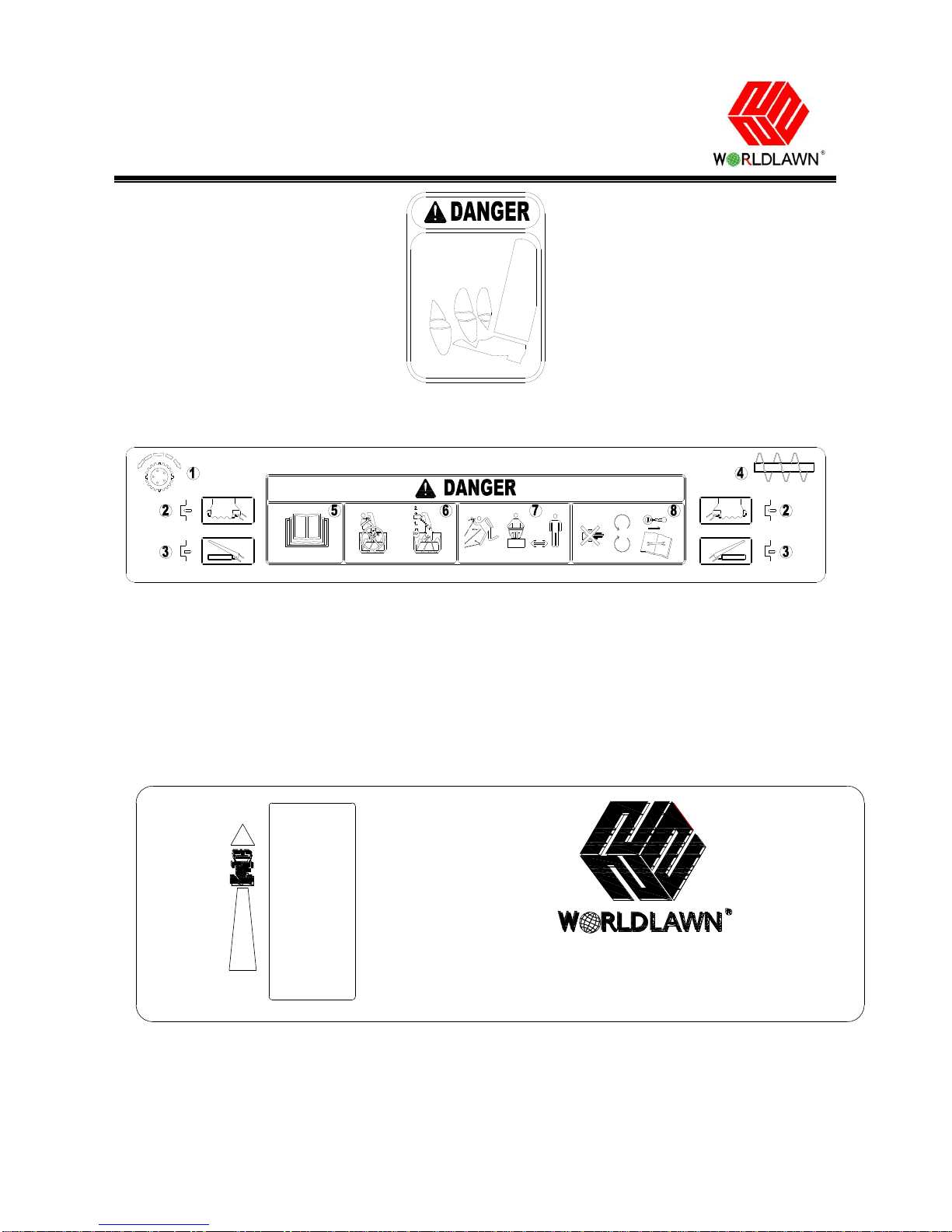
1.4.1 Do not put hands or feet near or under rotating
parts. Keep clear of the discharge opening at all times.
1.4.2 Exercise extreme caution when operating on or
crossing gravel drives, walks, or roads. Stay alert for
hidden hazards or traffic.
1.4.3 After striking a foreign object, stop the engine,
remove the wire from the spark plug, thoroughly
inspect the snow thrower for any damage, and repair
the damage before restarting and operating the snow
thrower.
1.4.4 If the unit should start to vibrate abnormally,
stop the engine and check immediately for the cause.
Vibration is generally a warning of trouble.
1.4.5 Stop the engine:
Whenever you leave the operating position.
When making any repairs, adjustments, or
inspections.
Before unclogging the auger/impeller housing or
discharge chute.
1.4.6 When cleaning, repairing, or inspecting the snow
thrower, stop the engine and make certain the
anger/impeller and all moving parts have stopped.
Disconnect the spark plug wire and keep the wire
away from the plug to prevent someone from
accidentally starting the engine.
1.4.7 Do not run the engine indoors, except when
starting the engine and for transporting the snow
thrower in or out of the building. Open the outside
doors; exhaust fumes are dangerous.
1.4.8 Exercise extreme caution when operating on
slopes.
1.4.9 Never operate the snow thrower without proper
guards and other safety protective devices in place and
working.
1.4.10 Never direct the discharge toward people or
areas where property damage can occur. Keep children
and others away.
1.4.11 Do not overload the machine capacity by
attempting to clear snow at too fast a rate.
1.4.12 Never operate the machine at high transport
speeds on slippery surfaces. Look behind and use care
when operating in reverse.
1.4.13 Disengage power to the auger/impeller when
snow thrower is transported or not in use.
1.4.14 Use only attachments and accessories approved
by the manufacturer of the snow thrower.
1.4.15 Never operate the snow thrower without good
visibility or light. Always be sure of your footing, and
keep a firm hold on the handles. Walk; never run.
1.4.16 Never touch a hot engine or muffler.
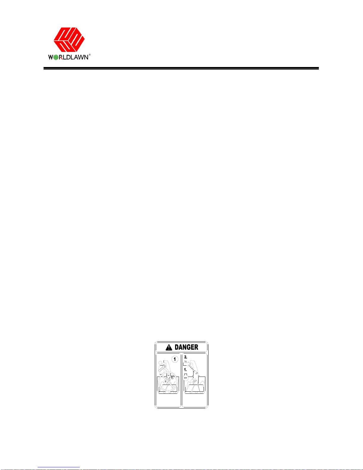
1.5 Clearing a Clogged Discharge Chute
Hand contact with the rotating rotor blades inside the
discharge chute is the most common cause of injury
associated with snow throwers. Never use your hand
to clean out the discharge chute.
To clear the chute:
Shut the engine off!
Wait 10 seconds to be sure the impeller blades
have stopped rotating.
Always use a clean-out tool, not your hands.
1.6 Maintenance and Storage
1.6.1 Check all fasteners at frequent intervals for
proper tightness to be sure the equipment is in safe
working condition.
1.6.2 Never store the machine with fuel in the fuel
tank inside a building where ignition sources are
present, such as hot water heaters or clothes dryers.
Allow the engine to cool before storing in any
enclosure.
1.6.3 Always refer to the Operator's Manual for
important details if the snow thrower is to be stored
for an extended period.
1.6.4 Maintain or replace safety and instruction labels,
as necessary.
1.6.5 Run the machine a few minutes after throwing
snow to prevent freeze-up of the auger/impeller
blades.