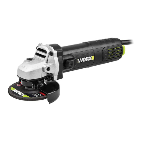
Worx Professional WU720 User manual

ANGLE GRINDER
Angle grinder
Угловая шлифовальная машина
Ketaslõikur
Leņķiskā slīpmašīna
Kampinis šlifuotuvas
•
•
•
•
•
Szlifi erka kątowa
Ъглов шлайф
Unghi polizor
Úhlová bruska
Uhlová brúska
•
•
•
•
•
EN 05
RU 14
ET 25
LV 34
LT 43
PL 52
BG 62
RO 72
CZ 82
SK 91
WU720 WU720.1


�


5
1
2
3
4
5
6
7
8
9
10
11
12
13
Component list
On-off switch
Switch lock-on button
Variable speed control
Hand grip areas
Anti-vibration auxiliary handle (2 positions)
Spindle lock button
Inner flange
Spindle
Out flange
Guard lock bolt
Guard screw (x3)
Spanner
Grinding disc
Not all the accessories illustrated or described are included in
standard delivery.
Noise and vibration data
A weighted sound pressure 95.5dB(A)
A weighted sound power 108.5dB(A)
Wear ear protection when sound pressure is over 85dB(A)
Typical weighted vibration 9.68m/s2
•
•
•
•
Technical data
Rated voltages 220V-240V~50Hz/60Hz
Rated power 1200W
Rated no load speed 2,800-10,000/min
Max. disc diameter 125mm
Spindle thread M14
Disc bore 22.2mm
Protection class / II
Machine weight 2.0Kg
•
•
•
•
•
•
•
•

6
Accessories
Spanner 1pc
Anti-vibration auxiliary handle 1pc
125mm metal grinding disc 1pc
We recommend that you purchase your accessories from the same
store that sold you the tool. Use good quality accessories marked
with a well-known brand name. Choose the type according to the
work you intend to undertake. Refer to the accessory packaging for
further details. Store personnel can assist you and offer advice.
•
•
•
1
2
3
4
5
6
Additional safety points for your
angle grinder
This power tool is intended to function as a grinder. Read all
safety warnings, instructions, illustrations and specifications
provided with this power tool. Failure to follow all instructions
listed below may result in electric shock, fire and/or serious injury.
Do not use accessories which are not specifically designed
and recommended by the tool manufacturer, Just because the
accessory can be attached to your power tool, it does not assure
safe operation.
The rated speed of the accessory must be at least equal to
the maximum speed marked on the power tool, Accessories
running faster than their rated speed can fly apart,
The outside diameter and the thickness of your accessory
must be within the capacity rating of your power tool.
Incorrectly sized accessories cannot be adequately guarded or
controlled.
The arbour size of wheels, flanges, backing pads or any other
accessory must properly fit the spindle of the power tool.
Accessories with arbour holes that do not match the mounting
hardware of the power tool will run out of balance, vibrate
excessively and may cause loss of control,
Do not use a damaged accessory, Before each use inspect
the accessory such as abrasive wheels for chips and cracks,
backing pad for cracks, tear or excess wear, wire brush for
loose or cracked wires, If power tool or accessory is dropped,
inspect for damage or install an undamaged accessory. After
inspecting and installing an accessory, position yourself and
bystanders away from the plane of the rotating accessory

7
7
8
9
10
11
12
and run the power tool at maximum no load speed for one
minute. Damaged accessories will normally break apart during this
test time.
Wear personal protective equipment. Depending on
application, use face shield, safety goggles or safety glasses,.
As appropriate, wear dust mask, hearing protectors, gloves
and shop apron capable of stopping small abrasive or
workpiece fragments. The eye protection must be capable of
stopping flying debris generated by various operations . The dust
mask or respirator must be capable of filtrating particles generated
by your operation Prolonged exposure to high intensity noise may
cause hearing loss.
Keep bystanders a safe distance away from work area.
Anyone entering the work area must wear personal
protective equipment. Fragments of workpiece or of a broken
accessory may fly away and cause injury beyond immediate area of
operation.
Hold power tool by insulated gripping surfaces only, when
performing an operation where the cutting accessory may
contact hidden wiring or its own cord. Cutting accessory
contacting a “live” wire may make exposed metal parts of the
power tool “live” and shock the operator.
Position the cord clear of the spinning accessory. If you lose
control, the cord may be cut or snagged and your hand or arm may
be pulled into the spinning accessory.
Never lay the power tool down until the accessory has come
to a complete stop. The spinning accessory may grab the
surface and pull the power tool out of your control,
Do not run the power tool while carrying it at your side.
Accidental contact with the spinning accessory could snag your
clothing, pulling the accessory into your body.
Regularly clean the power tool’s air vents. The motor’s fan will
draw the dust inside the housing and excessive accumulation of
powdered metal may cause electrical hazards
Do not operate the power tool near flammable materials.
Sparks could ignite these materials.
Do not use accessories that require liquid coolants. Using
water or other liquid coolants may result in electrocution or shock.
KICKBACK AND RELATED WARNINGS
Kickback is a sudden reaction to a pinched or snagged rotating
wheel, backing pad, brush or any other accessory. Pinching or
snagging causes rapid stalling of the rotating accessory which
in turn causes the uncontrolled power tool to be forced in the
direction opposite of the accessory’s rotation at the point of the
binding.
For example, if an abrasive wheel is snagged or pinched by the
workpiece, the edge of the wheel that is entering into the pinch
point can dig into the surface of the material causing the wheel
to climb out or kick out. The wheel may either jump toward or
away from the operator, depending on direction of the wheel’s
movement at the point of pinching Abrasive wheels may also break
under these conditions.
Kickback is the result of power tool misuse and/or incorrect
operating procedures or conditions and can be avoided by taking
proper precautions as given below.
13
14
15

8
Maintain a firm grip on the power tool and position your
body and arm to allow you to resist kickback forces,. Always
use auxiliary handle, if provided, for maximum control over
kickback or torque reaction during start-up. The operator can
control torque reactions or kickback forces, if proper precautions
are taken.
Never place your hand near the rotating accessory. Accessory
may kickback over your hand.
Do not position your body in the area where power tool will
move if kickback occurs, Kickback will propel the tool in direction
opposite to the wheel’s movement at the point of snagging.
Use special care when working corners, sharp edges etc.,
avoid bouncing and snagging the accessory. Corners, sharp
edges or bouncing have a tendency to snag the rotating accessory
and cause loss of control or kickback.
SAFETY WARNINGS SPECIFIC FOR GRINDING AND
ABRASIVE CUTTING OFF OPERATIONS:
Always use guard designed for the type of wheel you are
using. The guard must be securely attached to the power
tool and positioned for maximum safety, so the least amount
of wheel is exposed towards the operator. The guard helps
to protect operator from broken wheel fragments and accidental
contact with wheel.
Use only wheel types that are recommended for your power
tool and the specific guard designed for the selected wheel.
Wheels for which the power tool was not designed cannot be
adequately guarded and are unsafe.
Wheels must be used only for recommended applications.
For example: do not grind with the side of cut-off wheel,.
Abrasive cut-off wheels are intended for peripheral grinding, side
forces applied to these wheels may cause them to shatter.
Always use undamaged wheel flanges that are of correct
size and shape for your selected wheel. Proper wheel flanges
support the wheel thus reducing the possibility of wheel breakage.
Flanges for cut-off wheels may be different from grinding wheel
flanges.
Do not use worn down wheels from larger power tools.
Wheel intended for larger power tool is not suitable for the higher
speed of a smaller tool and may burst.
ADDITIONAL SAFETY WARNINGS SPECIFIC FOR ABRASIVE
CUTTING OFF OPERATIONS:
Do not “jam” the cut-off wheel or apply excessive pressure.,
Do not attempt to make an excessive depth of cut.
Overstressing the wheel increases the loading and susceptibility
to twisting or binding of the wheel in the cut and the possibility of
kickback or wheel breakage.
Do not position your body in line with and behind the
rotating wheel. When the wheel, at the point of operation, is
moving away from your body, the possible kickback may propel the
spinning wheel and the power tool directly at you.
When wheel is binding or when interrupting a cut for any
reason, switch off the power tool and hold the power tool
motionless until the wheel comes to a complete stop. Never
attempt to remove the cut-off wheel from the cut while the
wheel is in motion otherwise kickback may occur. Investigate
and take corrective action to eliminate the cause of wheel binding.
Do not restart the cutting operation in the workpiece,. Let
1
2
3
4
1
2
3
4
5
1
2
3
4

9
the wheel reach full speed and carefully reenter the cut. The
wheel may bind, walk up or kickback if the power tool is restarted
in the workpiece.
Support panels or any oversized workpiece to minimize the
risk of wheel pinching and kickback,. Large workpieces tend to
sag under their own weight. Supports must be placed under the
workpiece near the line of cut and near the edge of the workpiece
on both sides of the wheel.
Use extra caution when making a “pocket cut” into existing
walls or other blind areas. The protruding wheel may cut gas or
water pipes, electrical wiring or objects that can cause kickback.
5
6
Symbols
Read the manual
Double insulation
Warning
Wear eye protection
Wear dust mask
Wear ear protection
WEEE marking

10
1
2
Operation instructions
Note: Before using the tool, read the instruction book carefully.
ON/OFF SWITCH
Depress to start and release to stop your tool.
SWITCH LOCK-ON BUTTON
Depress on/off switch (1) then lock on button (2), release on/off
switch first and lock-on button second. Your switch is now locked on
for continuous use. To switch off your tool just depress and release
the on/off switch. (See A)
VARIABLE SPEED CONTROL
Adjust the thumb-wheel to increase or decrease the speed (See
B) according to the material, material thickness and disc/accessory
specification to be used (also possible during no load operation). See
Table 1 for general guidance on speed selection. Avoid prolonged use
at very low speeds as this may damage your angle grinder’s motor.
The Constant Speed Control electronic circuit inside your angle
grinder maintains a nearly constant speed even when your angle
grinder is under load.
(Table 1)
Material Speed setting
Grinding ferrous metals,cutting
stone,brick,etc,wire cup brush 5-6
Grinding or sanding non-ferrous metals,light
grinding work 3-5
Plolishing, light sanding work 1-3
HAND GRIP AREAS
Always hold your angle grinder firmly with both hands when
operating (See C).
ADJUSTABLE AUXILIARY HANDLE
You have the option of two working positions to provide the safest
and most comfortable control of your angle grinder (See D). The
handle is screwed clockwise into either hole on the sides of the gear
case.
SPINDLE LOCK BUTTON
Must only be used when changing a disc. Never press when the disc
is rotating.
DISC FITTING
The inner flange (7) is located over the spindle (8) and on the two
spindle flats. Locate the disc onto the inner flange and then the outer
flange (9) is screwed onto the spindle (See E). Press the spindle lock
onto the spindle (See F). Press the spindle lock firmly and tighten the
outer flange using your special spanner to clamp the disc (See F). The
pins on your special spanner locate in the holes on the outer flange.
Check the disc rotates freely and is securely clamped. Make a no load
test run for 20 seconds to check disc vibration and disc run out. To
remove a disc, reverse these instructions.
ADJUSTABLE OUTER FLANGE CLAMPING
The outer flange (9) should be adjusted to suit different disc
thicknesses. For thinner cutting or diamond discs the raised part of
the outer flange is fitted facing away from the disc (See Fig G.1).
For thicker grinding discs the raised part of the outer flange is fitted
3
4
5
6
7

11
facing the disc to provide improved support for the disc hole (See Fig
G.2). Always ensure your disc is securely clamped.
GUARD ADJUSTMENT
To move the guard you must release the guard lock bolt (10) using
the other end of the special spanner (See H). The guard can then be
rotated to provide maximum protection against sparks and debris.
Finally, tighten the guard bolt (10).
REMOVING THE GUARD
Only to be removed for use with sanding, flap disc and wire cup
brush accessories. Never remove your guard for any other working
conditions. Remove the disc, both flanges, guard bolt, screws x 3 (11)
and guard. Keep all parts in a safe place.
FITTING SANDING ACCESSORIES OR WIRE CUP BRUSH
Check the accessory specification for the rated speed, spindle thread
and other dimensions are correct for your angle grinder. Follow the
fitting instructions with your new accessory.
8
9
10
Work hints for your angle grinder
If your power tool becomes too hot, run at no load for 2-3 minutes to
cool the motor.
Never start your angle grinder with the disc/accessory in contact with
the work-piece.
Always start at no load to achieve maximum speed then start
working.
Do not force the disc to work faster, reducing the disc’s moving
speed means a longer working time.
Always work with a 10-20 angle between the disc and work-piece
when grinding. Larger angles will cut ridges into the work-piece and
affect the surface finish. Move the angle grinder across and back and
forth over the work-piece.
When using a cutting disc never change the cutting angle otherwise
you will stall the disc and angle grinder motor or break the disc. When
cutting, only cut in the opposite direction of the disc rotation. If you
cut in the same direction as the disc rotation the disc may push itself
out of the cut slot.
When cutting very hard material the best results can be achieved
with a diamond disc. When using a diamond disc it will become
very hot. If this happens you will see a full ring of sparks around the
rotating disc. Stop cutting and allow cooling at a no load speed for 2-3
minutes.
Always ensure the work-piece is firmly held or clamped to prevent
movement.

12
Maintenance
Remove the plug from the socket before carrying out any
adjustment, servicing or maintenance.
Your power tool requires no additional lubrication or maintenance.
There are no user serviceable parts in your power tool. Never use
water or chemical cleaners to clean your power tool. Wipe clean with
a dry cloth. Always store your power tool in a dry place. Keep the
motor ventilation slots clean. Keep all working controls free of dust.
Occasionally you may see sparks through the ventilation slots. This is
normal and will not damage your power tool.
If the supply cord is damaged, it must be replaced by the
manufacturer, its service agent or similarly qualified persons in order
to avoid a hazard.
Environmental protection
Waste electrical products should not be disposed of with
household waste. Please recycle where facilities exist. Check
with your local authorities or retailer for recycling advice.
Plug replacement
(UK & Ireland only)
If you need to replace the fitted plug then follow the instructions
below.
IMPORTANT
The wires in the mains lead are colored in accordance with the
following code:
BLUE =NEUTRAL BROWN = LIVE
As the colors of the wires in the mains lead of this appliance may not
correspond with the colored markings identifying the terminals in
your plug, proceed as follows. The wire which is colored blue must
be connected to the terminal which is marked with N. The wire which
is colored brown must be connected to the terminal which is marked
with L.
Note: If a moulded plug is fitted and has to be removed take great
care in disposing of the plug and severed cable, it must be destroyed
to prevent engaging into a socket.
Connect
Blue to N
(neutral)
Outer sleeve
firmly clamped Cable grip
Brown L (live)
13 Amp fuse approved
to BS1362
WARNING!
Never connect live
or neutral wires to
the earth terminal
of the plug. Only
fit an approved
13ABS1363/A plug
and the correct
rated fuse.

13
Declaration of conformity
We,
POSITEC Germany GmbH
Neuer Höltigbaum 6
22143 Hamburg
Declare that the product,
Description WORX Angle grinder
Type WU720 WU720.1
Complies with the following Directives,
EC Machinery Directive 98/37/EC
EC Low Voltage Directive 2006/95/EC
EC Electromagnetic Compatibility Directive 2004/108/EC
Standards conform to
EN 55014-1 EN 55014-2 EN 61000-3-2
EN 61000-3-3 EN 50144-2-3 EN 50144-1
2007/09/08
Jacky Zhou
POSITEC Quality Manager
•
•
•

14
1
2
3
4
5
6
7
8
9
10
11
12
13
Список компонентов
Выключатель питания
Кнопка фиксации выключателя
Регулятор скорости
Область захвата инструмента рукой
Дополнительная рукоятка (2 положения)
Кнопка блокировки шпинделя
Шайба опорная
Шпиндель
Гайка зажимная
Болт блокировки защитного кожуха
Винты защитного кожуха (x3)
Специальный гаечный ключ
Абразивный диск
Не все принадлежности, иллюстрированные или описанные
включены в стандартную поставку.
Характеристики шума и
вибрации
Звуковое давление 95.5dB(A)
Акустическая мощность 108.5dB(A)
Максимально допустимое звуковое давление без
использования средств защиты 85dB(A)
Измеренная вибрация 9.68m/s2
•
•
•
•
Технические характеристики
Напряжение 220V-240V~50Hz/60Hz
Потребляемая мощность 1200W
Скорость без нагрузки 2,800-10,000/min
Макс. диаметр круга 125mm
Резьба шпинделя M14
Диаметр отверстия круга 22.2mm
Двойная изоляция / II
Вес 2.0Kg
•
•
•
•
•
•
•
•

15
Принадлежности
Специальный гаечный ключ 1шт.
Дополнительная рукоятка 1шт.
Шлифовальный круг по металлу 125мм 1шт.
Рекомендуется приобретать все принадлежности в том же
магазине, где был приобретен инструмент. Используйте
качественные принадлежности с указанием общеизвестной
торговой марки. Более подробные сведения Вы можете
получить в рекомендациях в данном руководстве или на
упаковке принадлежностей. Помощь и консультацию можно
также получить у продавца.
•
•
•
1
2
3
4
Дополнительные меры
безопасности по обращению
с угловой шлифмашиной
Данный ручной инструмент предназначен для
работы в качестве шлифовальной машины.
Прочтите все предупреждения по технике
безопасности, инструкции, иллюстрации и
характеристики, прилагаемые к данному ручному
инструменту.Невыполнение всех нижеперечисленных
инструкций может привести к поражению электрическим
током, пожару и/или серьезному увечью.
Не пользуйтесь принадлежностями,
не предназначенными специально и
не рекомендованными изготовителем
инструмента. Сама лишь возможность установки той
или иной принадлежности в данный ручной инструмент не
обеспечивает безопасности эксплуатации.
Номинальная скорость принадлежности должна
быть не менее максимальной скорости, указанной
на ручном инструменте. При работе на скорости,
превышающей максимальную, принадлежность может
вылететь.
Внешний диаметр и толщина принадлежности
должна лежать в пределах характеристик
производительности ручного инструмента.
При неправильно выбранных размерах принадлежности
невозможно соответствующим образом оградить или
адекватно управлять ими.

16
5
6
7
Размер оправки дисков, фланцев, подпорных пластин или
любой другой принадлежности должен хорошо подходить
для шпинделя ручного инструмента. Принадлежности
с отверстиями для оправки, которые не совпадают с
монтажными деталями ручного инструмента будут терять
равновесие, сильно вибрировать и могут выходить из-под
контроля.
Не пользуйтесь поврежденными
принадлежностями.Перед каждым
использованием осмотрите принадлежность,
например шлифовальный диск, на наличие
сколов и трещин, подпорную пластину
– на трещины, разрывы и усиленный износ,
проволочную щетку – на отсутствие или
трещины в проволоке. Если ручной инструмент
или принадлежность упала, осмотрите
принадлежность на предмет повреждений
или установите невредимую принадлежность.
Осмотрев и установив принадлежность, отойдите
сами и отведите посторонних от плоскости
вращающейся принадлежности и запустите
ручной инструмент на максимальной скорости на
одну минуту. Обычно в течение такого пробного периода
поврежденные принадлежности разрываются.
Надевайте средства индивидуальной защиты.
В зависимости от применения, воспользуйтесь
защитной маской, защитными перчатками
или защитными очками. Если нужно, наденьте
пылезащитную маску, защитные наушники,
перчатки и цеховой фартук, который сможет
остановить мелкие абразивные частицы или
фрагменты заготовки. Средства защиты глаз
должны быть в состоянии остановить летящие осколки,
образующиеся при различных работах.Пылезащитная маска
или респиратор должны быть в состоянии фильтровать
частицы, образующиеся при работе. Длительное воздействие
интенсивного шума может привести к потере слуха.
Не разрешайте посторонним входить в рабочую
зону.Всякий, кто входит в рабочую зону, обязан
надевать средства индивидуальной защиты.
Фрагменты заготовки или сломавшейся принадлежности
могут вылетать и наносить увечья за пределами самьй
рабочей зоны.
Выполняя работы, во время которых режущая
принадлежность может касаться скрытой
проводки или шнура питания инструмента,
держите ручной инструмент только за
изолированные поверхности захвата. Если режущая
принадлежность коснется проводника под напряжением,
металлические детали ручного инструмента также могут
оказаться под напряжением, что приведет к поражению
оператора электрическим током.
Размещайте шнур подальше от вращающейся
принадлежности. Если вы утратите контроль над
инструментом, она может обрезать или зацепить шнур, а руку
может затянуть во вращающуюся принадлежность.
Ни в коем случае не кладите ручной инструмент,
пока принадлежность не остановится полностью.
Вращающаяся принадлежность может зацепиться за
поверхность и вытянуть ручной инструмент вне вашего
8
9
10
11

17
влияния.
Не запускайте ручной инструмент, держа его
рабочим концом к себе. При случайном контакте
вращающаяся принадлежность может зацепиться за одежду
и врезаться вам в тело.
Регулярно очищайте вентиляционные отверстия
ручного инструмента. Вентилятор двигателя затягивает
пыль внутрь корпуса, и чрезмерное скопление металлической
пыли может вызвать электрические опасности.
Не пользуйтесь ручным инструментом вблизи
огнеопасных материалов. Искры могут зажечь такие
материалы.
Не пользуйтесь принадлежностями, требующих
применения жидкостного охлаждения.
Использование воды или других жидких хладагентов
может привести к смертельному поражению или удару
электрическим током.
ОТДАЧА И ОТНОСЯЩИЕСЯ К НЕЙ
ПРЕДУПРЕЖДЕНИЯ
Отдачей называется внезапная реакция зажатого или
зацепленного вращающегося диска, подпорной пластины,
щетки или любой другой принадлежности. При зажиме
или зацепке происходит быстрый останов вращающейся
принадлежности, которое, в свою очередь, вызывает
движение неконтролируемого ручного инструмента в
направлении, противоположном вращению принадлежности в
точке соприкосновения.
Например, если шлифовальный диск зацепится или будет
зажат в заготовке, край диска, входящий в точку зажима,
может врезаться в поверхность материала, в результате
чего диск поднимется или выскочит. Диск может рвануться
или к оператору, или от него, в зависимости от направления
вращения диска в точке зажима. В этих условиях
шлифовальный диск может и сломаться.
Отдача происходит при неправильном применении и/или
неправильном способе работы с ручным инструментом.
Приняв должные меры предосторожности, описанные ниже,
ее можно избежать.
Крепко удерживайте ручной инструмент и
расположите свое тело и руку так, чтобы была
возможность противостоять силам отдачи.
Если есть дополнительная рукоятка, всегда
пользуйтесь ею, чтобы в максимальной мере
контролировать реакцией отдачи или момента
во время пуска.Оператор может контролировать момент
реакции или силы отдачи, если предпримет следующие меры
предосторожности.
Ни в коем случае не ставьте руку поблизости
вращающейся принадлежности.В результате отдачи
принадлежность может отскочить к руке.
Не стойте в зоне, в которую может отскочить
ручной инструмент в случае отдачи. Отдача увлечет
инструмент в направлении, противоположном движению
диска в точке зацепки.
Будьте особо осторожны при обработке углов,
острых краев и т. п. Избегайте рикошета и
зацепки принадлежности.На углах, острых краях
12
13
14
15
1
2
3
4

18
или при рикошете вращающаяся принадлежность обычно
зацепляется, что приводит к потере контроля и отдаче.
ПРЕДУПРЕЖДЕНИЯ ПО ТЕХНИКЕ БЕЗОПАСНОСТИ,
ОСОБО КАСАЮЩИЕСЯ ОПЕРАЦИЙ ШЛИФОВАНИЯ И
АБРАЗИВНОЙ РЕЗКИ
Всегда пользуйтесь ограждением,
предназначенным для используемого типа диска.
Ограждение должно быть прочно закреплено на
ручном инструменте и расположено так, чтобы
обеспечивать максимальную безопасность и
чтобы к оператору была обращена как можно
меньшая часть диска.Ограждение помогает защитить
оператора от фрагментов сломанного диска и от случайного
контакта с диском.
Пользуйтесь только теми типами дисков, которые
рекомендуются для вашего ручного инструмента,
и конкретным ограждением, предназначенным
для использования с выбранным диском.Диски, для
которых ручной инструмент не предназначен, невозможно
должным образом оградить, и они небезопасны.
Диски следует использовать только для
рекомендуемых применений.Например:не
выполняйте шлифование боковой поверхностью
отрезного диска.Абразивные отрезные диски
предназначены для окружного шлифования. Боковые силы,
прилагаемые к этим дискам, могут привести к их поломке.
Всегда пользуйтесь неповрежденными фланцами
дисков, которые имеют размер и форму, нужные
для выбранного диска.Подходящие фланцы дисков
поддерживают диск, снижая тем самым вероятность поломки
диска.Фланцы отрезных дисков могут отличаться от фланцев
шлифовальных дисков.
Не пользуйтесь изношенными дисками ручного инструмента
больших размеров. Диск, предназначенный для большего
ручного инструмента, не подходит для большей скорости,
которая возникает в меньшем ручном инструменте, и может
сломаться.
ДОПОЛНИТЕЛЬНЫЕ ПРЕДУПРЕЖДЕНИЯ ПО
ТЕХНИКЕ БЕЗОПАСНОСТИ ПРИ ОПЕРАЦИЯХ
АБРАЗИВНОЙ РЕЗКЕ
Не зажимайте отрезной диск и не прилагайте
чрезмерных усилий. Не пытайтесь выполнять
разрез чрезмерной глубины.Перегрузка диска
увеличивает нагрузку, восприимчивость к скручиванию или
изгибу диска в разрезе и возможность отдачи или поломки
диска.
Не располагайте своего тела по оси
вращающегося диска или за ним. Когда диск в
рабочей точке движется от вашего тела, возможная
отдача увлечет вращающийся диск и ручной инструмент
прямо на вас.
Когда диск изгибается или когда вы по какой-либо
причине прерываете резание, выключите ручной
инструмент и держите его неподвижно, пока диск
полностью не остановится.Ни в коем случае не
пытайтесь вывести отрезной диск из разреза при
вращающемся диске, иначе может произойти
отдача.Выясните причину изгиба диска и внесите
1
2
3
4
5
1
2
3

19
исправления, чтобы устранить причину изгиба диска.
Не возобновляйте резание, когда диск находится
в заготовке.Подождите, пока диск достигнет
полной скорости, и тогда введите его в разрез.Если
ручной инструмент снова запустить в заготовке, диск может
изогнуться, выйти или вызвать отдачу.
Удерживайте плиты или заготовку большого
размера, чтобы минимизировать риск захвата
диска или отдачи.Большим заготовкам свойственно
провисать под собственным весом.Опоры следует размещать
под заготовкой вблизи линии разреза и у края заготовки по
обе стороны диска.
Будьте особо осторожно при выполнении
углубления в существующих стенах или других
глухих местах.Выступающий диск может обрезать
газовые или водопроводные трубы, электрическую проводку
или предметы, вызывающие отдачу.
4
5
6
Условные обозначения
Прочтите инструкцию
Войная изоляция
Предупреждение
Наденьте защитные очки
Наденьте респиратор
Наденьте защитные наушники
Маркировка WEEE
Сертификат соответствия ГОСТ Р

20
1
2
Эксплуатация
Внимание: Перед использованием
инструмента, внимательно прочитайте
руководство по эксплуатации.
ВЫКЛЮЧАТЕЛЬ ПИТАНИЯ
Нажмите на клавишу выключателя питания, чтобы включить
дрель, и отпустите ее, чтобы инструмент остановился.
КНОПКА ФИКСАЦИИ ВЫКЛЮЧАТЕЛЯ
Нажмите на выключатель питания (1), затем на кнопку
фиксатора (2). после этого отпустите выключатель, а
затем кнопку фиксатора. Выключатель питания останется
постоянно включенным для непрерывной работы. Чтобы
выключить дрель, нажмите и отпустите выключатель питания.
.(см. рис. A)
РЕГУЛЯТОР ПЕРЕМЕННОЙ СКОРОСТИ
Большим пальцем вращайте колесико регулятора для
увеличения или уменьшения скорости (см. рис. B) в
соответствии с материалом, толщиной материала и данными
используемого круга/принадлежности (регулировка возможна
также при работе на холостом ходу). См. табл. 1 для общего
руководства по выбору скорости. Избегайте длительной
работы на очень малой скорости, т. к. это может привести к
повреждению двигателя угловой шлифмашины. Ваша угловая
шлифмашина оснащена электроникой для поддержания
постоянных оборотов вне зависимости от нагрузки.
(табл. 1)
Материал
Положение
регулятора
скорости
Шлифование твердых металлов;
резка камня, кирпича и т.д.; работа с
чашечными проволочными щетками
5-6
Шлифование цветных металлов, легкие
шлифовальные работы 3-5
Полирование, легкие шлифовальные
работы 1-3
ОБЛАСТИ ЗАХВАТА РУКОЙ
Крепко держите угловую шлифмашину обеими руками во
время работы (см. рис. С).
ДОПОЛНИТЕЛЬНАЯ РУКОЯТКА
Вы можете выбрать одно из двух рабочих положений для
обеспечения наиболее безопасного и удобного контроля за
шлифмашиной (см. рис. D). Рукоятка ввинчивается по часовой
стрелке в одно из боковых отверстий корпуса машины
КНОПКА БЛОКИРОВКИ ШПИНДЕЛЯ
Ее следует использовать только при замене круга.
Запрещается нажимать ее при вращающемся круге!
УСТАНОВКА КРУГА
Опорную шайбу (7) наденьте на шпиндель (8) и зафиксируйте
ее на двух фасках шпинделя. Установите круг на опорную
3
4
5
6
This manual suits for next models
1
Table of contents
Languages:
Other Worx Professional Grinder manuals