WR XL2 User manual

XL2ASSEMBLY MANUAL 74302 1/11
1
FIELD CULTIVATOR
ASSEMBLY INSTRUCTIONS
WIL-RICH
PO Box 1030
Wahpeton, ND 58074
PH (701) 642-2621
Fax (701) 642-3372
www.wil-rich.com
Printed in USA (74302) 1/11

XL2ASSEMBLY MANUAL 74302 1/11 2
WARRANTY
The only warranty Wil-Rich gives and the only warranty the dealer is authorized to give is as
follows:
We warrant products sold by us to be in accordance with our published specifications or those
specifications agreed to by us in writing at time of sale. Our obligation and liability under this
warranty is expressly limited to repairing, or replacing, at our option, within 12 months after date of
retail delivery, any product not meeting the specifications. We make no other warranty, express
or implied and make no warranty of merchantability or of fitness for any particular purpose.
Our obligation under the warranty shall not include any transportation charges or costs or installa-
tionor anyliability fordirect, indirector consequentialdamage or delay. If requested byus, products
or parts for which a warranty claim is made are to be returned transportation prepaid to our factory.
Any improper use, operation beyond rated capacity, substitution of parts not approved by us, or any
alteration or repair by others in such manner as in our judgment affects the product materially and
adversely shall void this warranty. No employee or representative is authorized to change this
warranty in any way or grant any other warranty.
Wil-Rich reserves the right to make improvement changes on any of our products without notice.
When warranty limited or not applicable: Warranty on hoses, cylinders, hubs, spindles, engines,
valves, pumps or other trade accessories are limited to the warranties made by the respective
manufactures of these components. Rubber tires and tubes are warranted directly by the respec-
tive tire manufacturer only, and not by Wil-Rich.
Warranty does not apply to any machine or part which has been repaired or altered in any way so
as in the our judgment to affect its reliability, or which has been subject to misuse, negligence or
accident.
A Warranty Validation and Delivery Report Form must be filled out and received by Wil-Rich
to initiate the warranty coverage.
WARRANTY CLAIMS PROCEDURE
1. The warranty form must be returned toWil-Rich within fifteen (15) working days from the repair
date.
2. Parts returned to Wil-Rich without authorization will be refused. The parts must be retained at
the dealership for ninety (90) days after the claim has been filed. If the Service Department would
liketo inspectthe parts,a packingslip willbe mailed to the dealer.The packing slipmust bereturned
with the parts. The parts must be returned prepaid within thirty (30) days of receiving authorization.
After the parts are inspected and warranty is verified, credit for the return freight will be issued to
the dealer.
3. Parts that will be scrapped at the dealership will be inspected by a Wil-Rich Sales Representa-
tive, District Sales Manager or Service Representative within the ninety (90) day retaining period.

XL2ASSEMBLY MANUAL 74302 1/11
3
ALL PERSONNEL INVOLVED WITH THE ASSEMBLY AND/OR OPERATION OF THIS
EQUIPMENT MUST BE INFORMED OF PROPER SAFETY PROCEDURES. OPERATOR’S/
ASSEMBLY MANUALS PROVIDE THE NECESSARY INFORMATION. IF THE MANUAL IS
LOST FOR A PARTICULAR IMPLEMENT, ORDER A REPLACEMENT AT ONCE.
OPERATOR’SANDASSEMBLY MANUALSAREAVAILABLEAT NO CHARGE UPON RE-
QUEST.
PERSONALSAFETY IS IMPORTANT!
ADDRESSINQUIRIESTO:WIL-RICHPOBOX1030
WAHPETON,ND58074
PH(701) 642-2621 FAX(701)642-3372
This Safety Alert symbol
means ATTENTION! BE-
COME ALERT YOUR
SAFETY IS INVOLVED!
TheSafetyAlert symbol iden-
tifies important safety mes-
sagesontheWil-Rich QuadX
Field Cultivator and in this
manual. When you see this
symbol, be alert to the possi-
bilityofpersonalinjuryordeath.
Follow the instructions in the
safetymessage.
Whyis SAFETY importanttoyou?
3 Big Reasons Accidents Disable and Kill
Accidents Cost
Accidents Can Be Avoided
SIGNALWORDS:
Note the use of the signal
words DANGER, WARNING
andCAUTION withthe safety
messages. The appropriate
signalword foreach message
has been selected using the
followingguidelines:
DANGER
An immediate and spe-
cific hazard which WILL
resultin severe personal
injury or death if the
proper precautions are
not taken.
WARNING
A specific hazard or un-
safe practice which
COULD result in severe
personal injury or death
if the proper precautions
are not taken
CAUTION
Unsafe practices which
COULD result in per-
sonal injury if proper
practices are not taken,
or as a reminder of good
safety practices.

XL2ASSEMBLY MANUAL 74302 1/11 4
CONTENTS
GENERALINFORMATION ..........................................5
TRANSPORTSAFETY ..................................................6
ASSEMBLY
OPENINGBUNDLE ....................................................7-8
AXLESANDWALKINGTANDEMS ............................. 9
11’&13’ MAINFRAME..............................................10
11’&13’ HITCHASSEMBLY ..................................... 11
HITCHASSEMBLY ......................................................12
7’,9’4”,&11’8”WING...............................................13
3’OUTERWING ..........................................................14
5’FLOATINGOUTERWINGW/GAUGEWHEEL .....15
6’FLOATINGOUTERWINGW/GAUGEWHEEL .....16
WINGLIFTCOMPONENTS .......................................17
OUTERWINGHYDRAULICGAUGEWHEEL ............18
HYDRAULICS-OUTERGAUGEWHEELS ..................19
PARALLELLINGGAUGEWHEEL .............................20
WINGREST11XL2ONLY ..........................................21
DEPTHINDICATOR ....................................................22
SINGLEPOINTDEPTHCONTROL ..................... 23-24
CHECKVALVE ....................................................... 25-27
BLANKPAGEFORNOTES .................................. 28-29
HOSECLAMP.............................................................30
MAINLIFT HYDRAULICS
11 XL219.............................................................31
11 XL225.............................................................32
11 XL230.............................................................33
13 XL232 ............................................................34
13 XL237 ............................................................35
WINGFOLD HYDRAULICS
11 XL219 & 25...................................................36
11 XL230.............................................................37
11 XL230 W/OUTER WINGS .........................38
13 XL232 & 37 ..................................................39
13 XL232 & 37 W/OUTER WINGS...............40
CHARGINGLIFTSYSTEM .........................................41
CHARGINGWINGFOLDSYSTEM............................42
SHANKPLACEMENTS
TWINSPRINGSHANK ASSEMBLY .........................43
SINGLESPRINGSHANK ASSEMBLY ......................44
11’MAINFRAME .........................................................45
13’MAINFRAME ........................................................46
7’WING ........................................................................47
9’4”WING...................................................................48
11’8”WING .................................................................49
2'OUTERRIGIDSTUB&3’OUTERWING ..............50
5'OUTERWING ..........................................................51
6’OUTERWING ..........................................................52
HDAUXILIARYHITCH ...............................................53
LIGHTS ........................................................................54
SAFETYDECALPLACEMENT ............................. 55-56
BLANKPAGEFORNOTES ........................................57

XL2ASSEMBLY MANUAL 74302 1/11
5
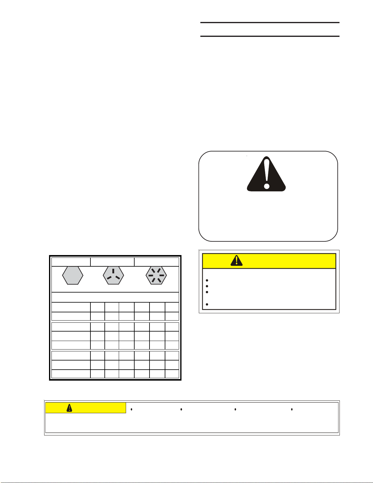
GRADE 2 GRADE 5 GRADE 8
TORQUE IN FOOT POUNDS
BOLT DIA 3/8 1/2 5/8 3/4 7/8 1
HEX HEAD 9/16 3/4 15/16 1-1/8 1-5/1 1-1/2
UNC GR2 18 45 89 160 252 320
UNC GR5 30 68 140 240 360 544
UNC GR8 40 100 196 340 528 792
UNF GR2 21 51 102 178 272 368
UNF GR5 32 70 168 264 392 572
UNF GR8 48 112 216 368 792 840
When replacing a bolt, use only a bolt of the
same grade or higher. Except in shear bolt
applications, where you must use the same
gradebolt.
Bolts with no markings are grade 2
Grade5 boltsfurnishedwith the machineare
identifiedby three radial lines on the head.
Grade8 boltsfurnishedwith the machineare
identifiedbysixradiallinesonthehead.
AllU-boltsare grade 5.
THISSYMBOLUSEDTOCALLYOURATTEN-
TIONTOINSTRUCTIONSCONCERNINGYOUR
PERSONALSAFETY.
BESURETOOBSERVEANDFOLLOWTHESE
INSTRUCTIONS
Removeall wires andarrangetheparts con-
veniently.
NOTE: Always wear safety glasses or
goggles and be careful when cutting wires
andsteelbandsastheyareundertensionand
willspring backwhencut.
Wherevertheterms"left"and"right"areused,
it must be understood to mean from a posi-
tionbehind and facingthemachine.
Lubricate all bearings and moving parts as
youproceedandmake surethey workfreely.
Loosely install all bolts connecting mating
partsbefore final tightening.
Whentightening bolts, they mustbetorqued
totheproper number of foot-pounds as indi-
cated in the table unless specified. It is im-
portantthat all bolts be kepttight.
Onnewmachines,all nutsandbolts mustbe
recheckedafter a few hours of operation.
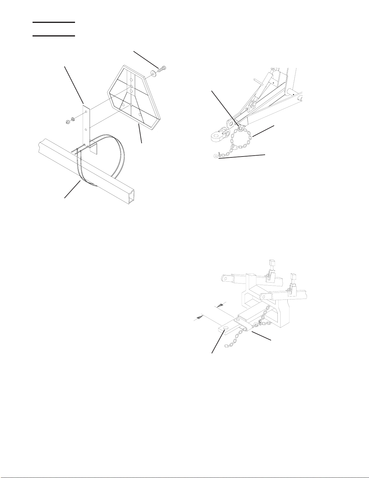
ASSEMBLY INFORMATION
Refer to Operator's Manual for safety instructions.
Do not stand or climb on machine when operating.
Use clean hazard flashers and SMV sign when
transporting.
Observe highway traffic regulations.
TO AVOID INJURY AND/OR MACHINE DAMAGE:
CAUTION
23325
FAILURE TO FOLLOW THESE
INSTRUCTIONS MAY RESULT IN PERSONAL
INJURYAND/OR EQUIPMENT DAMAGE.
CAUTION
53334
Just before and during
operation be sure no one is
on or around the
implement.
Before activating the
hydraulic system, check
hoses for proper
connections.
With wings down always
install hydraulic cylinder
channel lock(s) for
transporting.
Before lowering the wings for
the first time, make sure the
entiresystemhasbeen charged
withoil.
MODIFICATIONS
Itis the policy ofWil-Richto improve its prod-
uctswheneverpossibleandpracticaltodoso.
We reserve the right to make changes, im-
provements and modifications at any time
without incurring obligation to make such
changes, improvements on any equipment
soldpreviously.

XL2ASSEMBLY MANUAL 74302 1/11 6
SAFETY The safety chain should be hooked long
enoughtopermitfullturns.Unnecessaryslack
shouldbe takenup.
Intermediate support is to be used if there is
more than 6" of unsupported chain on either
sideof the primary attaching point.
The intermediate support should not be
mounted more than 6" from the primary at-
tachingpoint. (See figure below)
The intermediate support is available from
yourWil-Rich dealer.
SMVMOUNTINGBRACKET
SMV EMBLEM
NYLONTIE WRAP CI-77643
Thebracket providedis designedtomount to
numerousframe sizes andcanbeorientated
indifferentpositionstoavoidinterferencewith
implementcomponents.
TheSMV emblemisto besecuredas near to
therear and centered,oras near totheleftof
centerof implement as practical.
Emblemis to be 2 to 6 feet above theground
measuredfromtheloweredgeoftheemblem.
Keepsafetydecalsclean.Replaceanysafety
decals that are damaged, destroyed, miss-
ing, painted over or can no longer be read.
Replacement safety decals are available
throughyourdealer.
Thepurpose of the safety chain is to provide
anauxiliaryattachingsystemtoretainthecon-
nection between towing and towed machine
in the event of separation of the primary at-
tachingsystem.
1/4NCx3/4BOLT
SAFETYCHAIN
CLEVISEND TO
TRACTOR
SAFETYCHAIN
MOUNT
CI-77825
PRIMARYATTACHINGPOINT
INTERMEDIATE
SUPPORT
6"MAX

XL2ASSEMBLY MANUAL 74302 1/11
7
OPENING BUNDLE
Step #1
Laybundle down, supporting frame securely
36to 40 inches off the ground.
Step #2
Unfoldfront frame andboltintoplace using
3/4x2inchgrade 8 bolts as shown on main
frameand wing assembly pages.

XL2ASSEMBLY MANUAL 74302 1/11 8
OPENING BUNDLE
Step #3
After bundle is unfolded and the two frame
halves are bolted together remove shipping
standsand brackets.
After the shipping stands and brackets are
removedthe rest of the cultivator may be as-
sembledasshowninthisbook.
Remove
shippingstands
Remove
shippingbrackets

XL2ASSEMBLY MANUAL 74302 1/11
9
XL2MAIN AXLE & WALKING TANDEM
79144.PLT
AXLE & WALKING TANDEM 7’, 9’4” & 11’8” WINGS
PIN1x6-3/8
(68033)
1”FLAT
WASHER
(88196)
ROLLPIN
1/4x2-1/4
(42484)
3/4NCx2-3/4GR5
BOLT-(88841)
WINGAXLEASSY
LH -(220782)
RH-(220781)
10.8WING MAST
ANCHOR
(221261)INNERWING
19-7/8(INNER)
WHEEL ASSY
2” HUB &
SPINDLE
(14131)
5/8NCx4GR5
BOLT
(88298)
3/4NCx2-3/4GR5
BOLT
(88841)
PIN1x6-3/8
(68033)
1”FLAT
WASHER
(88196)
ROLLPIN
1/4x2-1/4
(42484)
5/8NCLOCK
NUT(88369)
12.6MASTANCHOR
(221262)
22-1/4

XL2ASSEMBLY MANUAL 74302 1/11 10
11’ & 13’ MAIN FRAME
(13’SHOWN)
700402
WINGREST
(240818-13FT)
12.6HYD CYL
(67683F1)
PIN1X2-3/8
(42473)
U-BOLT5/8X3X5-1/4
(88503)
PIN(1-1/4x3.38)
(68034) WASHER FLAT 1”
(88196) PIN1X6-3/8
(68033)
MASTTUBE
(67707)
3/4NCX2-3/4GR5BOLT
(88841)
3/4NCx2 GR8BOLT
(88290)
MACHINERYBUSHING
1-1/4IDx1-7/8ODx14GA
(88440)
MACHINERYBUSHING
1-1/4IDx1-7/8ODx14GA
(88440)
PIN(1-1/4x3.38)
(68034)
4X30HYDCYL
(51229F)
PIN1X2-3/8
(42473)
ASSY HDWR
74302-1

XL2ASSEMBLY MANUAL 74302 1/11
11
(13’ SHOWN)
11’ & 13' HITCH ASSEMBLY
79149-2
ADJUSTERASSEMBLY
(68036)
ADJUSTMENTSCREW
(68026)
CENTERHITCHBRACKET
(67937)
1-1/4NCJAMNUT
(88622)
MAINFRAMEHITCH
(68086)11’MAINFRAME
(233672)13’ MAINFRAME
PIN(1-1/4ODx5.13)
(68031)
MACHINERYBUSHING
1-1/4x1-7/8x14GA
(88440)
PIN(1-1/4ODx7.25)
(68032)
1-1/4NCx6-1/2GR5BOLT
(88349)
1-1/4NCJAMNUT(2)
(88622)
3/4NCx6GR5BOLT
(88293)
1/4x2-1/4 SPIROL PIN
(42484)
4HOLE PLATE
(3.75X4.69)
DIAMOND 5/8NCx3
x5-1/4U-BOLT
(88503)
RIGHTHITCHTUBE
3/4NCx5GR5
BOLT
PIN(1-1/4x3.38)
(68034)
PIN(1-1/4x5.13)
(68031)
LIFTSIDEPLATE
4HOLE PLATE
(3.5X4.75)
1-1/2ODx1-1/4IDSPRING
TENSIONBUSHING
(33535)
1 FLAT WASHER
(88196)
PIN(1x6.38)
(68033)
1/4x2-1/4
SPIROLPIN
(42484)
LINKAGE
5/8NCx2GR5BOLT
(88294)
LEFTHITCH
TUBE
HITCHTUBE
11 XL
2
CENTERLIFTTUBE
(68084 11’)
13&16EXCEL
CENTERLIFT
TUBE(67743
13’MAIN)
PIN(1-1/4x6-1/8)
(68030)
ASSY HDWR
74302-2

XL2ASSEMBLY MANUAL 74302 1/11 12
HITCH ASSEMBLY CONTINUED
SAFETYCHAIN
(24459)
CLAMPHALF
1/2HOSE
(238400)
JACK
(24415)
3/8NCx5x4U-
BOLT(89069)
3/8FLAT
WASHER
(88282)
3/8LOCK
WASHER
(88362)
3/8NCHEX
NUT
(88103)
HITCHBOLT
(11638)
DUALHITCH
(18236)
1-1/4SLOTTED
NUT(88350)
3/16x2COTTER
PIN(88133)
CLEVISHITCH
(USED ON 11 MF
ONLY)
1NCx7GR8
BOLT(88687)
1/4FLAT
WSAHER
(88261)
1NCLOCK
NUT(88348)
1/4NCx3/4
GR5BOLT
(88993)
TUBE-
OPERATOR’S
MANUAL
TUBE
HOLDER
(234313) UTILITY
POLE
(236142)
LIGHTPLUG
RETAINER
(223329)
1/4LOCK
WASHER
(88262)
1/4NCNUT
(88172)
1/4NCx1GR5
BOLT(88203) RUBBER
EDGING
(236092)
5/16NCx1-3/4
GR5BOLT
(88480)
CLAMPHALF
3/8HOSE
(220645)
BASE PLATE
(221443)
TOPPLATE
(221445)
700160

XL2ASSEMBLY MANUAL 74302 1/11
13
7’, 9' 4” & 11’8” WING
700404
BOLT1X6NC
(88264)
BOLT5/8X1-1/2
(88577)
SEE PAGE 17
SEE PAGE 20
WASHER FLAT 1”
(88196)
PIN1X6-3/8
(68033)
WINGADJUSTARM
(67709)
3/4NCx2 GR8BOLT
(88290)
10.8HYD CYL
(67688F1)
MACHINERYBUSHING
1-1/4IDx1-7/8ODx14GA
(88440)
PIN(1-1/4x3.38)
(68034)
PIN1X2-3/8
(42473)
PLATE
(241810)
WINGTUBE
(220776)
NUTNLK1”
(89075)
ASSY HDWR
74302-3

XL2ASSEMBLY MANUAL 74302 1/11 14
700407
3FTOUTERWING
(241882-RH)
(241883-LH)
5/8NCx3-1/2
GR5BOLT
(88292)
1NCLOCKNUT
(89075)
1NCx6GR5BOLT
(88264)
5/8NCx3x5-1/4U-BOLT
(88503)
OUTERWINGREST
(68066)
PLATE
(67934) 1NCx5GR5BOLT
(88312)
LINKAGEARM
(67903)
ROLLPIN
(42484)
PIN(1x3-1/4)
(42473)
1 FLAT WASHER
(88196)
SHIM
(51469) 1/2NCx1-1/2GR5
BOLT(88475)
WINGHINGE
(67932)
1NCx5GR5BOLT
(88312)
5/8NCx3x5-1/4U-BOLT
(88503)
1NCLOCKNUT
(89075)
1NCLOCKNUT
(89075)
3' OUTER WING
HINGE AREA
TOP VIEW
37-3/16”
NOTE: POSITION WING REST TO CONTACT
OUTER TUBE WHEN FOLDED.
NOTE: DO NOT OVERTIGHTEN WING
FOLD LINKAGE BOLTS. LINKS NEED
TO ROTATE FREELY.
STACKSHIMSASREQUIRED
TOCONTROLWING LEVEL
ASSY HDWR
74302-4

XL2ASSEMBLY MANUAL 74302 1/11
15
700405
5FTOUTERWING
(241884-RH)
(241885-LH)
5/8NCx3-1/2
GR5BOLT
(88292)
1NCLOCK
NUT(89075)
1NCx6GR5
BOLT(88264)
5/8NCx3x5-1/4U-
BOLT(88503)
OUTER WINGREST
(68066)
PLATE
(67934)
1NCx5GR5BOLT
(88312)
LINKAGEARM(67903)
PIN(1x3-1/4)(42473)
1FLATWASHER(88196)
1/2NCx1-1/2GR5
BOLT(88475)
WING HINGE
(67932)
5/8NCx3x5-1/4
U-BOLT
(88503)
1NCLOCKNUT
(89075)
WING HINGE
(68024-LH)
(68023-RH)
TOPADJUSTASSY(15485)
5/8NCx2-1/2x3-3/4U-BOLT(88311)
GAUGEWHEEL LEG(15475)
1/2NCLOCKNUT
(88304)
95Lx15WHEELASSY(16290)
1-3/4"HUB &SPINDLE (41233)
1/2NFx3GR5BOLT(88313)
5/8NCx4x3-1/4U-BOLT
(88388)
1/2NCx1-1/2GR5
BOLT(88475)
BACKING
PL ATE
(26817) 12"SADDLE STUB(49025)
5’ FLOATING OUTER WING W/GAUGE WHEEL
44-1/16”
NOTE: POSITION WING REST TO CONTACT
OUTER TUBE WHEN FOLDED. NOTE: DO NOT OVERTIGHTEN
WING FOLD LINKAGE BOLTS.
LINKS NEED TO ROTATE FREELY.
1/4x2-1/2
ROLLPIN
(42484)
WINGFOLDSTOP(222156)
HOLDSOUTERWINGAPPROX
LEVELWITH MAIN FRAME,
REMOVEIF OUTERWING
DOWN -FLOATISREQUIRED
ASSY HDWR
74302-5

XL2ASSEMBLY MANUAL 74302 1/11 16
6’ FLOATING OUTER WING W/GAUGE WHEEL
5/8NCx3-1/2
GR5BOLT
(88292)
1NCLOCK
NUT(89075)
1NCx6GR5
BOLT
(88264)
OUTER WINGREST
(68066)
NOTE: POSITION WING REST TO CONTACT
OUTER TUBE WHEN FOLDED.
WINGFOLDSTOP(222156)
HOLDSOUTERWINGAPPROX
LEVELWITH MAIN FRAME,
REMOVEIF OUTERWING
DOWN -FLOATISREQUIRED
HINGE AREA
TOP VIEW
700406
6FTOUTERWING
(241886-RH,241887-LH)
5/8NCx3x5-1/4U-
BOLT(88503)
PLATE
(67934)
1NCx5GR5BOLT(88312)
LINKAGEARM
(67903)
PIN(1x3-1/4)
(42473)
1 FLAT WASHER
(88196)
1/2NCx1-1/2GR5
BOLT(88475)
WING HINGE
(67932)
5/8NCx3x5-1/4
U-BOLT
(88503) 1NCLOCKNUT(89075)
WING HINGE
(68024LH)
(68023RH)
TOPADJUSTMENTASSY
5/8NCx2-1/2x3-3/4U-BOLT(88311)
GAUGEWHEEL LEG(15475)
1/2NCLOCKNUT(88304)
95Lx15WHEELASSY(16290)
1-3/4"HUB &SPINDLE (41233)
1/2NFx3GR5BOLT(88313)
5/8NCx4x3-1/4U-BOLT
(88388)
NOTE: DO NOT OVERTIGHTEN
WING FOLD LINKAGE BOLTS.
LINKS NEED TO ROTATE FREELY.
1/4x2-1/2
ROLLPIN(42484)
ASSY HDWR
74302-6

XL2ASSEMBLY MANUAL 74302 1/11
17
1NCNYLON
LOCK NUT
(89075)
1NCx6GR5BOLT
(88264)
1NCx3-1/2
GR5BOLT
(88447)
5/8NCx1-3/4
GR5BOLT
(88838)
NOTE: SPECIAL WING LIFT STRAP MOUNTING, WING FOLD STUBS AND WING
LIFT LINK LENGTH ARE NECESSARY WHEN 3’ 5’ OR 6’ WINGS ARE ADDED.
SEE BOXED CALLOUTS.
1 FLAT WASHER
(88196)
2NDWINGLIFTSTRAP
(REQUIRED ON 9’4”
&11’8” WING ONLY)
1STWINGLIFTSTRAP
(REQUIRED ON ALL WINGS)
31”(2PL)
1NCNYLON
LOCK NUT
(89075)
1NCx3GR5BOLT
(88399)
WINGLIFTBUSHING
(1.032IDx1-1/4 ODx 1.06)
(48523)
WING LIFT COMPONENTS
5/8NCx3x5-1/4
U-BOLT(88503)
700413
WINGLIFTLINK
STANDARD LINK = 11” C TO C
SPECIAL LINK = 12-1/4” C TO C
WINGLINK STRAP
(SPECIAL MOUNT)
1ST HOLE
WINGLINK STRAP
(STANDARD MOUNT)
2ND HOLE
WINGFOLDSTUBS-
REQ’DWITH 3’,5’ OR6’
WING.
NOTE:SPECIAL WINGLIFT
LINKS AND WING FOLD STUBS
ARE PACKED WITH THE 3’,5’
ORWINGS, IFREQUIRED.

XL2ASSEMBLY MANUAL 74302 1/11 18
OPTIONALOUTER WING HYDRAULIC GAUGE WHEEL
OUTER FLOATING WING HYD GAGE WHEEL.DWG
1-3/4HUB&
SPINDLEASSY
(41233)
95Lx15 WHEELASSY
(16290)
CASTER
WHEEL LEG
(240360)
1/2x3NFGR5 BOLT
(88313)
1/2NFLOCK
NUT(88304)
STOP
COLLAR
(14189)
3/8NCNUT
(88162)
3/8NCx3
GR5BOLT
(88531)
1NCNYLON
LOCKNUT
(89075) PIN1x2-3/8
(42473)
GAUGE
WHEELPIVOT
(220850)
UPPERGAUGE
WHEELARM
(221100) LOWERGAUGE
WHEELARM
(222961)
GAUGEWHEEL
MOUNT(222961)
5/8FLAT
WASHER
(88277)
1-1/2STOP
COLLAR HYDRAULIC
CYLINDER4x9.3
W/TOP BP
(220761F1)
1/4x2-1/4
ROLLPIN
(42484)
ADJUST
ROD
(54621)
OUTERWINGANCHOR
(LEFTSHOWN)
1-1/4NCJAM
NUT(88622)
PIVOTBOLT
(221336) 1NCx6
GR5BOLT
(88264)
5/8NCx2
GR5BOLT
(88294)
5/8NCx3x5-1/4
GR5U-BOLT
(88503)
5/8NCx4x3-1/4
GR5U-BOLT
(88388)
ASSY HDWR
74302-7
(242216)BREAKASSY

XL2ASSEMBLY MANUAL 74302 1/11
19
HYDRAULICS-OUTER GAUGE WHEELS
RETURNHOSE
UNION8MJ x8MJ
(13239)
3/8x108FF
HOSE
( 4 )
ELB 8MORB x
8MJ(25580)
UNION8MJ x8MJ
(13239)
700002
4x9.3HYDCYLINDER

XL2ASSEMBLY MANUAL 74302 1/11 20
PARALLEL LINK GAUGE WHEEL
700429
GAUGEWHEEL
PIVOTBRACKET
(220850)
3/8NCHEX
NUT
(88103)
3/8LOCK
WASHER
(88362)
CASTERWHEEL
LEG(240360)
PIVOTBOLT
1x6.88
(221336)
LOWERGAUGE
WHEELARM.
(222961)
UPPERGAUGE
WHEELARM
(221100)
5/8NCx3x5-1/4
GR5U-BOLT
(88503)
1NCx6
GR5BOLT
(88264)
GAUGEWHEEL
MOUNT(220853)
5/8NCx4x3-1/4
GR5U-BOLT
(88388)
1NCNYLON
LOCKNUT
(89075)
STOP
COLLAR
(14189)
3/8NCx3
GR5BOLT
(88531)
ASSY HDWR
74302-8
ADJUSTER
ROD(9.5)
(69799)
1-1/4”NC
JAMNUT
(88622)
ADJUST-
MENTROD
(48890) 1”NCNUT
(88125)
(242216)
BREAKASSY
)
GAUGEWHEEL
ADJUSTMENT
BRKT (220843
)
Table of contents
Popular Tiller manuals by other brands

Craftsman
Craftsman 917.292493 owner's manual

White Outdoor
White Outdoor Roto Boss 850 215-418-190 Parts list and instruction manual

Poulan Pro
Poulan Pro HDF825X Repair parts manual

ATI Corporation
ATI Corporation Preseeder 365 Operator's manual

MTD
MTD 219-405-000 owner's guide

Husqvarna
Husqvarna DT22 Operator's manual