wurth 0715 58 770 Quick guide

VIELFACH MESSZANGE
PROFESSIONAL
CLAMP MULTIMETER
PROFESSIONAL
Art. 0715 58 770
Originalbetriebsanleitung
Translation of the original operating instructions
Manuale istruzioni di funzionamento
Traduction des instructions de service d’origine
Traducción del manual de instrucciones de
servicio original
Vertaling van de originele gebruiksaanwijzing

.................................... 3 – 8
.................................... 9 – 14
.................................... 15 – 20
.................................... 21 – 26
.................................... 27 – 32
.................................... 33 – 38

3
Sie haben eine Vielfachmesszange Professional erworben und wie danken Ihnen für das Vertrauen.
Um die optimale Benutzung Ihres Geräts zu gewährleisten, bitten wir Sie:
• diese Bedienungsanleitung sorgfältig zu lesen
• die Benutzungshinweise genau zu beachten.
Bedeutung der verwendeten Symbole:
ACHTUNG, GEFAHR! Sobald dieses Gefahrenzeichen irgendwo erscheint, ist der Benutzer verpichtet,
die Anleitung zu Rate zu ziehen.
Anlegen oder Entfernen der Zange von nicht isolierten oder blanken Leitern unter gefährlicher Span-
nung ist erlaubt.
Batterie 9 V.
Die CE-Kennzeichnung bestätigt die Übereinstimmung mit den europäischen Richtlinien.
Das Gerät ist durch eine doppelte bzw. verstärkte Isolation geschützt.
Der durchgestrichene Mülleimer bedeutet, dass das Produkt in der europäischen Union gemäß der
WEEE-Richtlinie 2012/19/EG einer getrennten Elektroschrott-Verwertung zugeführt werden muss. Das
Produkt darf nicht als Haushaltsmüll entsorgt werden.
AC – Wechselstrom.
AC und DC – Wechsel- und Gleichstrom.
Erde.
ACHTUNG! Gefahr eines elektrischen Schlags.
Dieses Gerät und sein Zubehör entsprechen den Sicherheitsnormen IEC 61010-1 und IEC 61010-2-032 in der
Messkategorie III für Spannungen bis 1000 V oder Messkategorie IV für Spannungen bis 600 V in geschlos-
senen Räumen, bei einem Verschmutzungsgrad von maximal 2 und bis zu einer Meereshöhe von maximal
2000 m.
Die Nichtbeachtung der Sicherheitshinweise kann zu Gefahren durch elektrische Schläge, durch Brand oder
Explosion, sowie zur Zerstörung des Geräts und der Anlage führen.
• Der Benutzer bzw. die verantwortliche Stelle müssen die verschiedenen Sicherheitshinweise sorgfältig lesen
und gründlich verstehen.
• Wenn das Gerät in unsachgemäßer und nicht spezizierter Weise benutzt wird, kann der eingebaute Schutz
nicht mehr gewährleistet sein und eine Gefahr für den Benutzer entstehen.
SICHERHEITSHINWEISE
Schnellstart-Anleitung

4
• Verwenden Sie das Gerät niemals in explosionsgefährdeter Umgebung oder in der Nähe von brennbaren
Gasen.
• Verwenden Sie das Gerät niemals an Netzen mit höheren Spannungen oder Messkategorien als den
angegebenen.
• Beachten Sie stets die angegebenen maximalen Spannungen und Ströme zwischen den Anschlussbuchsen
und gegenüber Erde.
• Verwenden Sie das Gerät niemals, wenn es beschädigt, unvollständig oder schlecht geschlossen erscheint.
• Prüfen Sie vor jeder Benutzung den einwandfreien Zustand der Isolierung der Messleitungen, des Gehäuses
und des Zubehörs. Teile mit auch nur stellenweise beschädigter Isolierung müssen für eine Reparatur oder für
die Entsorgung ausgesondert werden.
• Verwenden Sie ausschließlich das mitgelieferte Zubehör (Messleitungen, Prüfspitzen usw. …). Die Verwen-
dung von Zubehör mit niedrigerer Bemessungsspannung oder Messkategorie verringert die zulässige Span-
nung bzw. Messkategorie auf den jeweils niedrigsten Wert des verwendeten Zubehörs
• Beachten Sie stets die angegebenen Umgebungsbedingungen.
• Verändern Sie niemals das Gerät und ersetzen Sie niemals Bauteile durch sog. „gleichwertige“. Reparaturen
und Einstellungen dürfen nur von zugelassenem Fachpersonal vorgenommen werden.
• Ersetzen Sie die Batterie sobald das Symbol in der Anzeige erscheint. Klemmen Sie sämtliche
Anschlüsse ab bevor Sie das Batteriefach önen.
• Verwenden Sie eine persönliche Schutzausrüstung wenn es die Umstände erfordern.
• Halten Sie die Hände stets fern von unbenutzten Anschlüssen des Geräts.
• Fassen Sie Messleitungen, Prüfspitzen, Krokodilklemmen und Zangenstromwandler immer nur hinter dem
Fingerschutz an.
• Aus Sicherheitsgründen und um Überlastungen der Geräteeingänge zu vermeiden, dürfen Kongurations
einstellungen nur ohne Anschluss an gefährliche Spannungen vorgenommen werden.
Denition der Messkategorien:
CAT II: Kreise, die direkt an die Niederspannungs-Installation angeschlossen sind.
Beispiele: Stromanschluss von Haushaltsgeräten oder tragbaren Elektrowerkzeugen.
CAT III: Stromversorgungskreise in der Elektro-Installation eines Gebäudes.
Beispiele: Verteilerschränke, Trennschalter, Sicherungen, stationäre Maschinen und Geräte.
CAT IV: Quellenstromkreise in der Niederspannungs-Elektro-Installation eines Gebäudes.
Beispiele: Anschluss an das Stromnetz, Energiezähler und Schutzeinrichtungen.
MESSKATEGORIEN
5
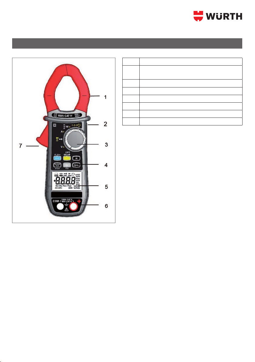
Nr. Bezeichnung
1 Zangenbacken mit Zentriermarken
(siehe Anschlusshinweise)
2 Fingerschutz-Wulst
3 Drehschalter
4 Funktionstasten
5 Anzeige
6 Anschluss-Buchsen
7Önungstaste
1 GERÄTEVORSTELLUNG
6
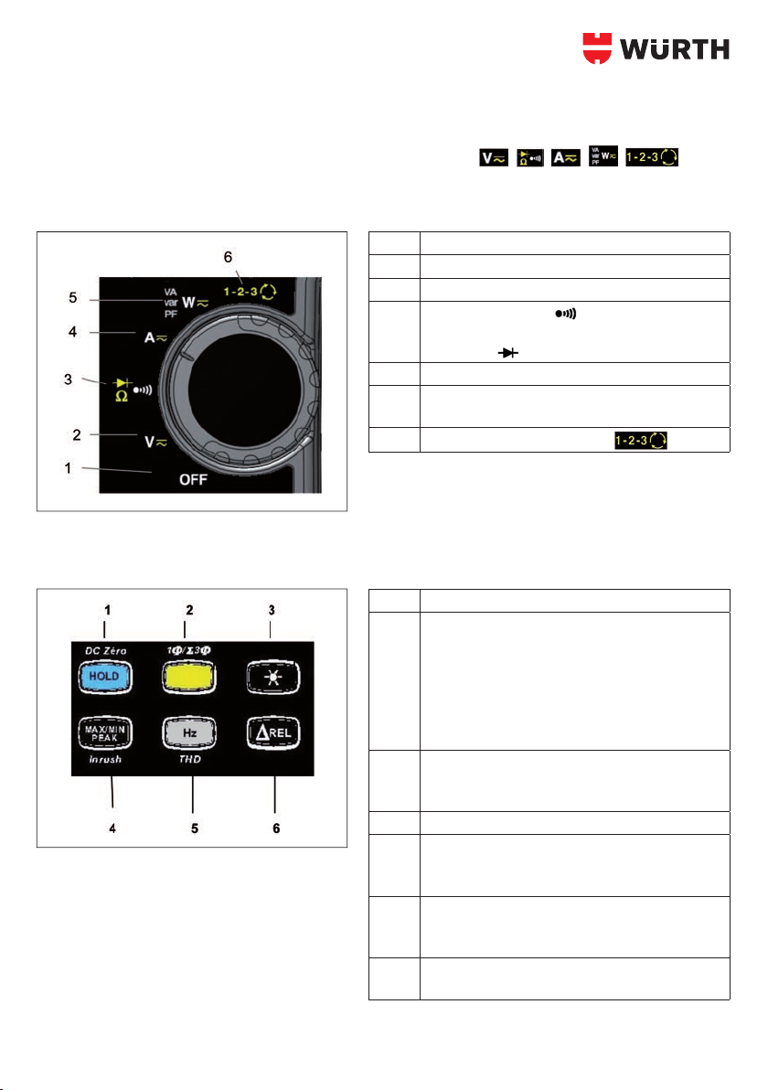
1.1 DREHSCHALTER
Der Drehschalter hat sechs Stellungen: OFF für Aus und die Stellungen , , , , , für die
vier Messfunktionen. Das Einschalten einer Messfunktion wird vom Gerät durch ein Tonsignal bestätigt. Die
einzelnen Messfunktionen sind in der Tabelle unten beschrieben.
Nr. Messfunktion
1 OFF – Abschalten der Vielfachmesszange
2Spannungsmessung (V) AC, DC, AC+DC
3 Durchgangsprüfung
Widerstandsmessung Ω
Diodentest
4Strommessung (A) AC, AC+DC
5Leistungsmessung (W, var, VA) und Berechnung
des Leistungsfaktors (PF) in AC, DC, AC+DC
6Anzeige der Drehfeldrichtung
1.2 FUNKTIONSTASTEN
Nr. Funktion
1 HOLD – der aktuelle Wert wird in der Anzeige
gespeichert
Nullpunkt-Kompensation bei ADC/AAC+DC/WDC
und WAC+DC-Messungen
Kompensation der Messleitungswiderstände in
den Funktionen Widerstandsmessung und
Durchgangsprüfung
2Umschalten der Messart (AC, DC, AC+DC)
Auswahl von Einphasen- bzw. Drehstrommes-
sungen
3 Anzeigebeleuchtung ein- bzw. ausschalten
4 MAX-/MIN-Funktion ein- bzw. ausschalten
INRUSH-Funktion bei Strommessung ein- bzw.
ausschalten
5Frequenzmessung (Hz),
Oberschwingungsmessung (THD)
Anzeige der Messwerte für W, VA, var und PF
6Einschalten der RelativMessung ΔREL –
Anzeige von Relativ bzw. Dierenzwerten

7
1.3 ANZEIGE
Nr. Funktion
1 Anzeige der ausgewählten Messfunktion
(Tasten)
2 Digitale Anzeige des Messwerts und der Einheit
3 Anzeige der MAX-/MIN-/PEAK-Funktion
4Anzeige der Stromart (AC oder DC)
5 Anzeige der Gesamtleistung bei Drehstromnet-
zen
6 Anzeige der am Drehschalter gewählten
Messfunktion
7 Anzeige, dass Batterie verbraucht ist
1.3.1 Symbole in der Anzeige
Symbol Bedeutung
AC Wechselstrom bzw. -spannung
DC Gleichstrom bzw. -spannung
AC+DC Wechsel- und Gleichstrom bzw. -spannung
ΔREL Relativwert in Bezug zu einem Referenzwert
ΔRef Referenzwert
HOLDFunktion (Anzeigespeicherung)
Max Maximaler RMS-Wert
Min Minimaler RMS-Wert
Peak+ Maximaler Scheitelwert
Peak- Minimaler Scheitelwert
Gesamtleistung bei symmetrischen Drehstromnetzen
VVolt (Spannung)
Hz Hertz (Frequenz)
WWirkleistung (Watt)
AAmpère (Stromstärke)
%Prozentwert
ΩOhm (Widerstand)
mVorsatz Milli- für Maßeinheiten
kVorsatz Kilo- für Maßeinheiten
var Blindleistung
VA Scheinleistung
PF Leistungsfaktor (Power Factor)
8
Symbol Bedeutung
THDfGesamt-Oberschwingungsanteil in Bezug zur Grundschwingung
THDrGesamtOberschwingungsanteil in Bezug zum Echteektivwert des Signals
Anzeige der Drehfeldrichtung
Kompensation der Messleitungswiderstände
Durchgangsprüfung
Diodentest
Ständige Anzeige (Abschalteautomatik ausgeschaltet)
Anzeige, dass Batterie verbraucht ist
Das Symbol O.L (Over Load) erscheint, wenn ein Messbereich überschritten wurde.
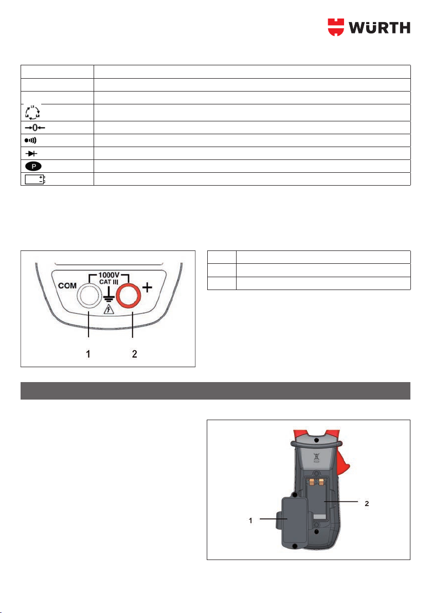
1.4 ANSCHLUSSBUCHSEN
Die Anschlussbuchsen sind wie folgt zu benutzen:
Nr. Funktion
1COMAnschluss (kalter Messpunkt, Minuspol)
2+ Anschluss (heißer Messpunkt, Pluspol)
2.1 ERSTE INBETRIEBNAHME
Setzen Sie die Batterie wie folgt in die Vielfach-
messzange ein:
1. Önen Sie mit einem Schraubendreher den
Batteriefachdeckel (Nr. 1) auf der Rückseite
der Messzange.
2. Setzen Sie die 9 VBatterie (Nr. 2) in das
Batteriefach ein und achten Sie dabei auf die
richtige Polarität.
3. Setzen Sie den Deckel wieder auf und ver-
schließen Sie ihn mit der Schraube.
2 BENUTZUNG
9
You have just acquired an clamp multimeter and we thank you.
For best results from your device:
• read this user manual attentively,
• observe the precautions for its use.
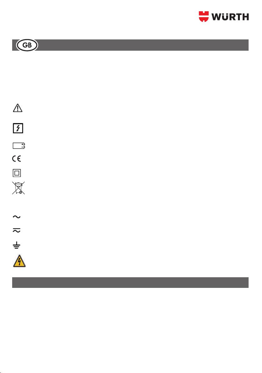
Meanings of the symbols used on the device
Danger. The operator agrees to refer to this data sheet whenever this danger symbol is encountered.
Application or withdrawal authorized on uninsulated or bare conductors at dangerous voltages.
9 V battery.
The CE marking indicates compliance with European directives.
Double insulation or reinforced insulation.
Selective sorting of wastes for the recycling of electrical and electronic equipment within the European
Union.
In conformity with directive DEEE 2012/19/EC: this equipment must not be treated as household
waste.
AC – Alternating current.
AC and DC – Alternating and direct current.
Earth.
Risk of electric shock.
This device complies with safety standards IEC610101 and 610102032 for voltages of 1000V in category
III or 600 V in category IV at an altitude OF less than 2000m, indoors, with a degree of pollution not exceed-
ing 2.
These safety instructions are intended to ensure the safety of persons and proper operation of the device. If the
tester is used other than as specied in this data sheet, the protection provided by the device may be impaired.
• The operator and/or the responsible authority must carefully read and clearly understand the various pre-
cautions to be taken in use.
• If you use this instrument other than as specied, the protection it provides may be compromised, thereby
endangering you.
PRECAUTIONS FOR USE
Start Guide

10
• Do not use the instrument in an explosive atmosphere or in the presence of ammable gases or fumes.
• Do not use the instrument on networks of which the voltage or category exceeds those mentioned.
• Do not exceed the rated maximum voltages and currents between terminals or with respect to earth.
• Do not use the instrument if it appears to be damaged, incomplete, or not properly closed.
• Before each use, check the condition of the insulation on the leads, housing, and accessories. Any element of
which the insulation is deteriorated (even partially) must be set aside for repair or scrapped.
• Use leads and accessories rated for voltages and categories at least equal to those of the instrument. If not,
an accessory of a lower category lowers the category of the combined Clamp + accessory to that of the
accessory.
• Observe the environmental conditions of use.
• Do not modify the instrument and do not replace components with „equivalents“. Repairs and adjustments
must be done by approved qualied personnel.
• Replace the battery as soon as the symbol appears on the display unit. Disconnect all cords before
opening the battery compartment cover.
• Use personal protective equipment when conditions require.
• Keep your hands away from the unused terminals of the instrument.
• When handling the test probes, crocodile clips, and clamp ammeters, keep your ngers behind the physical
guard.
• As a safety measure, and to avoid repeated overloads on the inputs of the device, we recommend perform-
ing conguration operations only when the device is disconnected from all dangerous voltages.
Denitions of the measurement categories:
CAT II: Circuits directly connected to the lowvoltage installation.
Example: power supply to household electrical appliances and portable tools.
CAT III: Power supply circuits in the installation of the building.
Example: distribution panel, circuitbreakers, xed industrial machines or devices.
CAT IV: Circuits supplying the lowvoltage installation of the building.
Example: power lines, meters, and protection devices.
MEASUREMENT CATEGORIES
Table of contents
Languages:
Popular Multimeter manuals by other brands


Gossen MetraWatt
Gossen MetraWatt METRAmax 6 operating instructions

PeakTech
PeakTech 4000 Procedure of calibration

YOKOGAWA
YOKOGAWA 90050B user manual

Gossen MetraWatt
Gossen MetraWatt METRALINE DMM16 operating instructions

Fluke
Fluke 8846A Programmer's manual

Tempo Communications
Tempo Communications MM200 instruction manual


