WynMax WMBX-3011-2701 series User manual

WMBX-3011-2701 series
User Manual Rev.01 Jun. 2011

WMBX-3011-2701 series User Manual 2
All rights reserved. No part of this publication may be reproduced in any forms or by
any means without prior written permission of the publisher.
All trademarks are property of the respective owners.
All product specifications are subject to change without prior notice.
□WMBX-3011-2701 x 1
□60W DC12V Adapter x 1
□Power cord (US) x 1
□Food pad x 4
□Screws pack x 1
□Wall mount kit x 1
□VESA mount kit x 1 (option)
□Driver CD (Include user manual) x 1
STANDARD:
□WMBX-3011-2701
Mini-BOX with Atom N270 CPU with 1xVGA, 5xCOM, 2xLAN, 4xUSB, DDR2
SODIMM max up to 2GB, CF and 2.5" HDD support, mini-PICe for WLAN
expansion(option), wall mount kit, 60W DC12V Adapter, smart fan design.
OPTION:
□VESA mount kit for WMBX-3011 series
Ordering Information
Packing List
Statement

WMBX-3011-2701 series User Manual 3
Contents
Chapter 1 Product Information..........................................................................................4
1.1 General Description.......................................................................................................4
1.2 Features............................................................................................................................5
1.3 Dimensions......................................................................................................................6
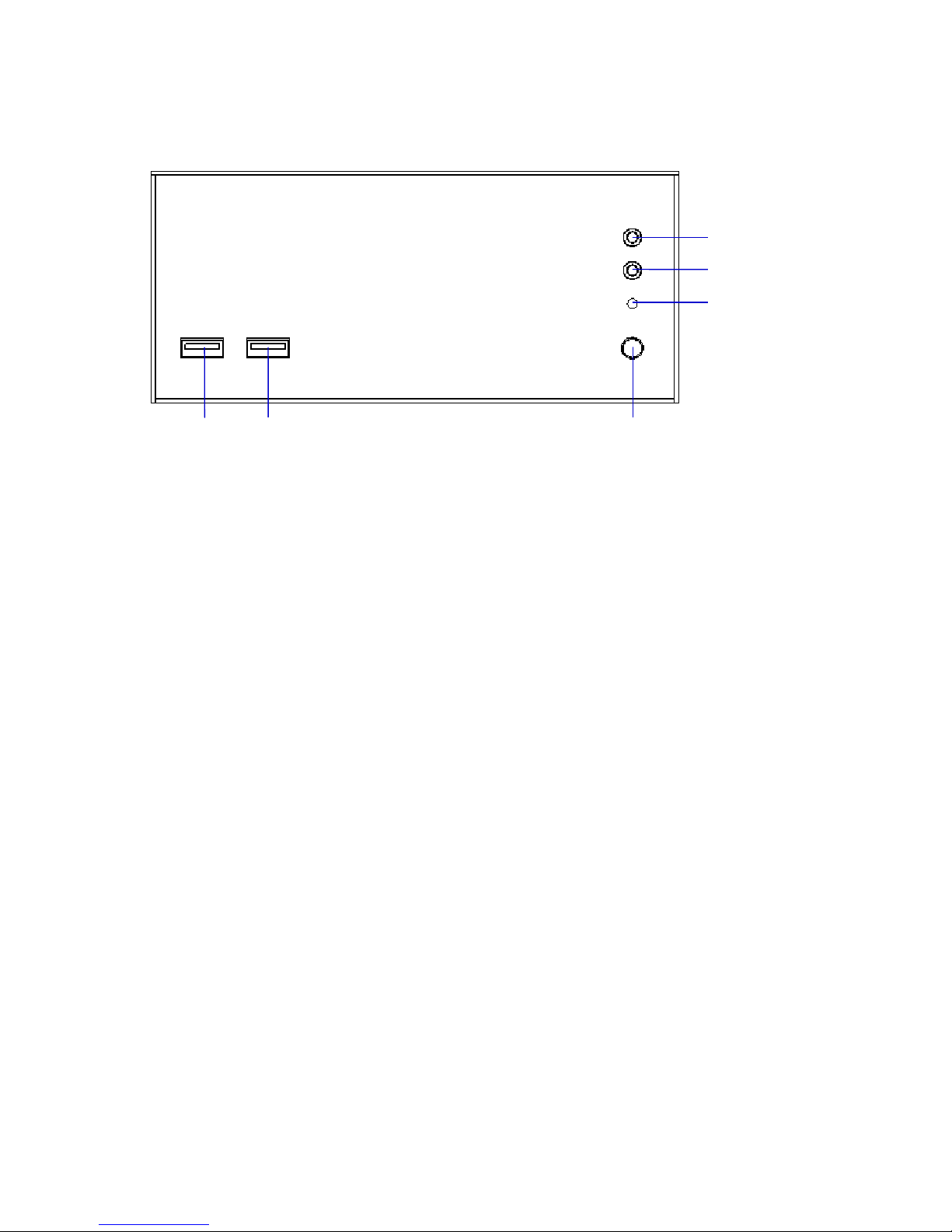
1.4 I/O Outlets.........................................................................................................................7
1.5 M/B PCB Layout..............................................................................................................9
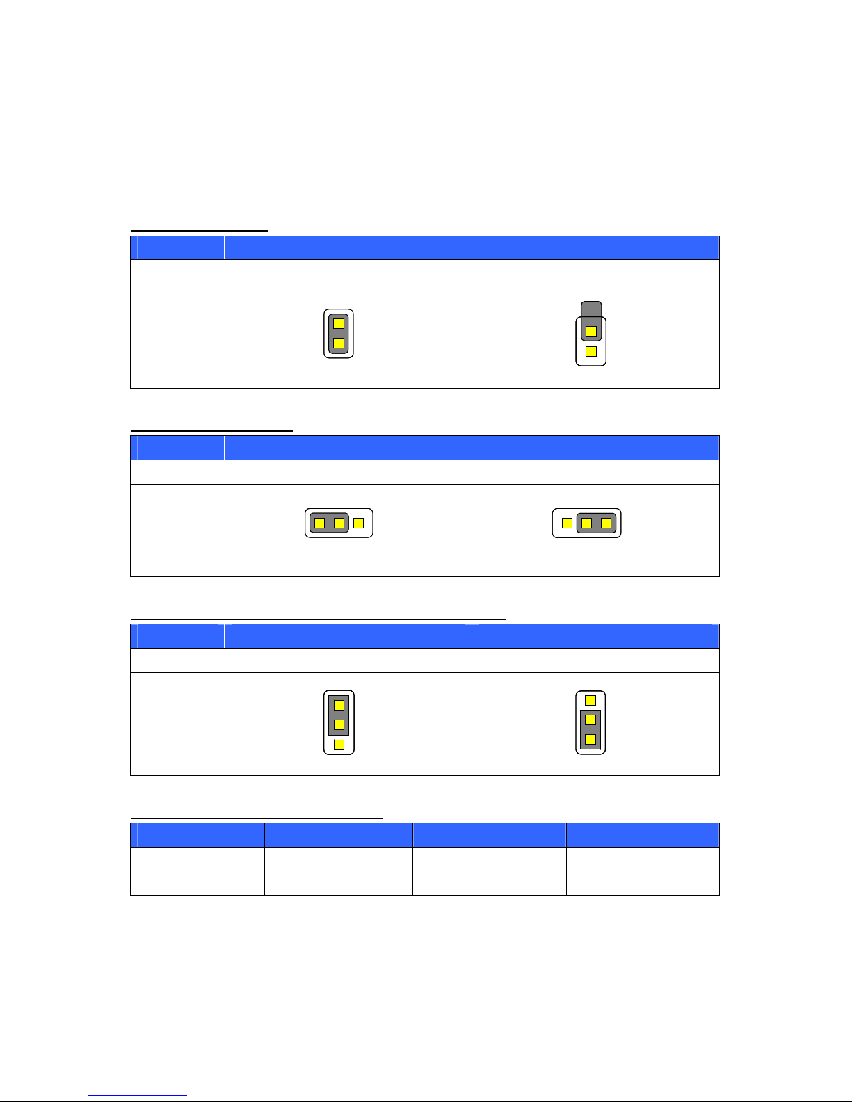
1.6 Jumper Setting..............................................................................................................10
1.7 Connector Function List.............................................................................................13
1.8 Internal Connector Pin Define...................................................................................14
Chapter 2 Hardware installation......................................................................................18
2.1 Install the memory module........................................................................................18
2.3 Installing the memory module..................................................................................19
Chapter 3 BIOS Setup........................................................................................................21
3.1 Main Menu......................................................................................................................21
3.2 Standard CMOS Features...........................................................................................22
3.3 Advanced BIOS Features...........................................................................................23
3.4 Advanced Chipset Features ......................................................................................26
3.5 Integrated Peripherals.................................................................................................28
3.6 Power Management Setup.........................................................................................34
3.7 PnP/PCI Configurations..............................................................................................36
3.8 PC Health Status...........................................................................................................37
3.9 Frequency/Voltage Control........................................................................................38
3.10 Load Fail-Safe Defaults.............................................................................................39
3.11 Load Optimized Defaults..........................................................................................40
3.12 Set Supervisor Password ........................................................................................41
3.13 Set User Password ....................................................................................................42
3.14 Save & Exit Setup.......................................................................................................43
3.15 Exit Without Saving...................................................................................................44
Chapter 4 Drivers Installation..........................................................................................45
4.1 Intel Chipset Device Software...................................................................................45
4.2 Intel Graphic Media Accelerator Driver ..................................................................48
4.3 LAN Driver......................................................................................................................51
4.4 Audio Driver...................................................................................................................53
Appendix-A Watchdog.......................................................................................................54
Appendix-B GPIO................................................................................................................56

WMBX-3011-2701 series User Manual 4
Chapter 1 Product Information
This chapter introduces product features, jumper and connector information.
1.1 General Description
The WMBX-3011-2701 series is a Mini BOX PC system that can support Atom N270
processors. WMBX-3011-2701 series support Windows® 2000, Windows® XP,
Windows® XP embedded, and Windows® 7, which is suitable for the most endurable
operation.

WMBX-3011-2701 series User Manual 5
1.2 Features
Construction Heave duty steel
CPU Intel Atom N270 1.6GHz processor onboard
System memory 1 x 200-pin DDR2 400/533/667 SO DIMM SDRAM, max.
up to 2GB
FSB 533MHz
Chipset Intel 945GSE + ICH7M
BIOS Award 16MB SPI
System I/O
Front I/O:
2 x USB
Rear I/O:
2 x USB, 2 x LAN, 1 x VGA,
5 x COM(4 x RS-232, 1 x RS-232/422/485),
1 x Audio(Mic-in, Audio-out, Line-in),
1 x WLAN (optional)
Watch dog timer Interval: Programmable 1~255 sec.
Storage support 1 x CF and 1 x 2.5" HDD
Expansion slot 1 x mini-PCIe
System Indicators 1 x Power LED, 1 x HDD LED
System controls 1 x Power on switch, 1 x Reset switch
Mounting Kit Wall mount kit
VESA mount kit (option)
Power Supply AC 60W adapter, Input: AC 100~240V~2A 50-60Hz,
Output: DC12V@5A
Operating Temperature 0°C~45°C (32°F~140°F)
Storage temperature -20°C~80°C (-68°F~176°F)
Relative Humidity 0%~90% (non-condensing)
Dimensions 160mm(W) x 140mm(D) x 70mm(H)
6.3"(W) x 5.5"(D) x 2.75"(H)
Weight Gross: 2.6Kg/5.72Lb
Net: 2.0Kg/4.4Lb
Standard Color Black

WMBX-3011-2701 series User Manual 6
1.3 Dimensions
The following diagrams show dimensions and outlines of the WMBX-3011-2701
series.

WMBX-3011-2701 series User Manual 7
1.4 I/O Outlets
FRONT
1. USB
2. USB
3. Power on button
4. Power status LED
5. HDD status LED
6. Reset button
1 2 3
4
5
6

WMBX-3011-2701 series User Manual 8
BACK
7. Antenna hole
8. LAN Port (LAN2)
9. COM Port (COM3)
10.LAN Port (LAN1)
11.USB Port (2 port)
12.VGA Port
13.COM Port (COM2)
14.COM Port (COM1)
15.Antenna hole
16.Audio (Line in)
17.Audio (Mic in)
18.Audio (Line out)
19.COM Port (COM5)
20.COM Port (COM4)
21.DC12V input
97 8 14
10 11 12 13
16 17 18 19 20 21
15

WMBX-3011-2701 series User Manual 9
1.5 M/B PCB Layout
1
2
7
8
1
2
7
8
1615
2
1
2
30
29
51
1
9
2
10
1
9
2
10
1
9
2
10
1
9
2
10
1
9
2
10
S1S4S7
S1S4S7
62
51
2
1
11
6
1
61
9
10
2
1
9
10
2
1
Mini PCI-E
SATA1 SATA2 LAN2 LAN1 USB1
USB0
VGA COM1
JLVDS_VDD18
INV18
LVDS18
COM2
JCOM1
JCOM_SEL
J1
DIO
SATA_PWR1
COM3
COM4
COM5
AUDIO
JCF_SEL
JIDE_SEL USB3 USB2 KB/MS FP
JCMOS
DC12V_IN1
CPUFAN
CF
(Bottom Side)
DIMM
(Bottom Side)

WMBX-3011-2701 series User Manual 10
1.6 Jumper Setting
WNA-3011-2701 series has a number of jumpers inside the chassis that allows you
to configure the system to suit the application. The table below lists the functions of
various jumpers.
J1:AT/ATX Select
Pin No. 1-2 2-NA
Function AT Power mode ATX Power mode (Default)
Jumper
Setting
JCMOS:CMOS Clear
Pin No. 1-2 2-3
Function Normal Operation (Default) Clear CMOS Contents
Jumper
Setting
JCF_SEL:Compact Flash ( Master / Slave ) Select
Pin No. 1-2 2-3
Function Master Mode Slave Mode (Default)
Jumper
Setting
JCOM1:COM1 (5V/12V/RI) Select
Pin No. 1-2 3-4 5-6
Function +5V Modem Ring In
(Default)
+12V
1 2 31 2 3
1 2 31 2 3
1
2
3
1
2
3
1
2
3
1
2
3
1
2
1
2
1
2
1
2
1
2

WMBX-3011-2701 series User Manual 11
Jumper Setting
JCOM_SEL:COM2 Select (1/5)
Pin No. 5-6, 11-13, 12-14, 19-21, 20-22
Function RS-232 (Default)
Jumper
Setting
JCOM_SEL:COM2 Select (2/5)
Pin No. 3-4, 9-11, 10-12, 17-19, 18-20
Function RS-422
Jumper
Setting
JCOM_SEL:COM2 Select (3/5)
Pin No. 1-2, 9-11, 10-12, 23-24
Function RS-485
Jumper
Setting
6 4 2
5 3 1
6 4 2
5 3 1
6 4 2
5 3 1
6 4 2
5 3 1
6 4 2
5 3 1
6 4 2
5 3 1
2 24
1 23
2 24
1 23
2 24
1 23
2 24
1 23
2 24
1 23
2 24
1 23

WMBX-3011-2701 series User Manual 12
JCOM_SEL:COM2 Select (4/5)
Pin No. 15-16
Function RS-422 RX 100ΩTermination
Jumper
Setting
JCOM_SEL:COM2 Select (5/5)
Pin No. 7-8
Function RS-422 TX 100Ω/ RS-485 Termination
Jumper
Setting
JLVDS_VDD18:
Pin No. 1-2 2-3
Function LCD Power 5V LCD Power 3.3V (Default)
Jumper
Setting
2 24
1 23
2 24
1 23
2 24
1 23
2 24
1 23
3
2
1
3
2
1
3
2
1
3
2
1

WMBX-3011-2701 series User Manual 13
1.7 Connector Function List
Connector Function Note
AUDIO Line-in, Line-out, MIC-In Connector
CF Compact Flash Connector
COM1 COM port DB9 Connector
COM2,3,4,5 COM port Connector
CPU FAN System FAN
DC12V_IN1 DC12V Input
DIMM DDR2 SO-DIMM
DIO Digital Input/output
FP Front Panel Connector
INV_18 18bit LCD Inverter connector
KB/MS KB/MS PS2 Connector
LAN1-2 RJ-45 Connector
LVDS_18 18bit LCD Connector
Mini PCI-E Mini PCIE Connector
SATA1-2 SATA Connector
SATA_PWR1 SATA Power
USB1 USBx2 Stack Connector
USB2-3 USBx2 Connector
VGA VGA Connector

WMBX-3011-2701 series User Manual 14
1.8 Internal Connector Pin Define
Audio: Audio Connector with Box-header (2.0 mm)
Pin No. Signal Pin No. Signal
1 LINE_R_IN 2 LINE_L_IN
3 GND 4 GND
5 LINE_R_OUT 6 LINE_L_OUT
7 GND 8 GND
9 MIC_R_IN 10 MIC_L_OUT
COM2-5: COM Connector with Box-header (2.0 mm)
Pin No. Signal Pin No. Signal
1 DCD 2 DSR
3 RXD 4 RTS
5 TXD 6 CTS
7 DTR 8 RI
9 GND 10 N/A
COM2: RS 422 Serial Port with Box-header (2.0 mm)
Pin No. Signal Pin No. Signal
1 DCD TX- 2 NC
3 RXD TX+ 4 NC
5 TXD RX+ 6 NC
7 DTR RX- 8 NC
9 NC 10 NC
COM2: RS 485 Serial Port with Box-header (2.0 mm)
Pin No. Signal Pin No. Signal
1 DCD DATA- 2 NC
3 RXD DATA+ 4 NC
5 NC 6 NC
7 NC 8 NC
9 NC 10 NC

WMBX-3011-2701 series User Manual 15
CPUFAN: CPUFAN Connector with (2.54 mm)
Pin No. Signal
1 GND
2 +12V
3 Speed Sense
4 PWM Control
DC12V_IN1: DC12V Power Input Connector
Pin No. Signal
1 GND
2 GND
3 +12V
4 +12V
DIO: Digital IO Connector with Pin Header (2.0 mm)
Pin No. Signal Pin No. Signal
1 D_Out0 2 D_IN0
3 D_Out1 4 D_IN1
5 D_Out2 6 D_IN2
7 D_Out3 8 D_IN3
9 +12V 10 +5V
11 GND 12 Key
FP: Front Panel Connector with Pin Header (2.54 mm)
Pin No. Signal Pin No. Signal
1 Power LED+ 2 HDD LED+
3 N/C 4 HDD LED-
5 Power LED- (GND) 6 Suspend LED+
7 RESET+ 8 Suspend LED-
9 RESET-(GND) 10 Speaker-
11 Key 12 N/C
13 Power Button+ 14 N/C
15 Power Button-(GND) 16 Speaker +(+5V)

WMBX-3011-2701 series User Manual 16
INV18: LCD Inverter Connector with Box-header (2.5 mm)
Pin No. Signal
1 +12V
2 +12V
3 GND
4 Back Light Control
5 Back Light Enable#
KB/MS: Keyboard and Mouse Connector with Box-header (2.0 mm)
Pin No. Signal
1 +5V
2 Mouse Data
3 Mouse Clock
4 Keyboard Data
5 Keyboard Clock
6 GND
LVDS_18: 18 bit LCD Connector with Box-header(1.0mm)
Pin No. Signal Pin No. Signal
1 GND 2 GND
3 N/C 4 N/C
5 A_CLK+ 6 A_CLK-
7 A_DATA2+ 8 A_DATA2-
9 A_DATA1+ 10 A_DATA1-
11 A_DATA0+ 12 A_DATA0-
13 GND 14 GND
15 NC 16 NC
17 B_CLK+ 18 B_CLK-
19 B_DATA2+ 20 B_DATA2-
21 B_DATA1+ 22 B_DATA1-
23 B_DATA0+ 24 B_DATA0-
25 DDC_CLK 26 DDC_DATA
27 +3.3V 28 +3.3V
29 +3.3V 30 +3.3V

WMBX-3011-2701 series User Manual 17
SATA_PWR1: SATA Power Connector with Box-header (2.0 mm)
Pin No. Signal
1 +5V
2 +5V
3 GND
4 GND
5 +12V
6 +12V
USB2-3:USB Connector with Pin Header (2.0 mm)
Pin No. Signal Pin No. Signal
1 +5V 2 GND
3 USB DATA- 4 USB DATA+
5 USB DATA+ 6 USB DATA-
7 GND 8 +5V

WMBX-3011-2701 series User Manual 18
Chapter 2 Hardware Installation
WMBX-3011-2701 series are convenient for various hardware configurations, such
as Memory Module, HDD, Compact Flash. The chapter 2 will show you how to install
the hardware. The information is shown as bellow:
2.1 Install memory module
Step 1: Remove the cover screws at the bottom (2pcs).
Step 2: Add 2.5” SATA HDD screws (4pcs).
Step 3: Connect SATA + Power cable.

WMBX-3011-2701 series User Manual 19
2.2 Install Compact Flash Card
Insert Compact Flash Card.
2.3 Install memory module
Insert memory module.
2.4 Install mini-PCIe expansion module
Insert mini-PCIe module (full size only).

WMBX-3011-2701 series User Manual 20
2.5 Install wall mount kit
Connect wall mount kit screws (4pcs).
2.6 Installing the foot pad
Connect foot pad screws (4pcs).
Note: Wall mount kit and foot pad only can select one
2.7 Install the VESA mount kit
Connect VESA mount kit screws (4pcs).
Connector Wall mount kit screws on VESA mount kit (4pcs).
Table of contents