X-cam A10-3H User manual

X-CAM A10-3H 3 Axis Gimbal for GOPRO
User Manual ( V2 00 )
The X-CAM A10-3H 3 Axis Gimbal has been setup and calibrated for use
with GOPRO cameras, it is ready to use straight from the box
Specifications:
Weight: 280g ( without GOPRO )
Stabilization Frequency: 200Hz
Input Voltage (DC IN): 7.4v ~ 22.2v ( 2S ~ 6S Lipo )
Tilt Travel: +-90 degrees; Rolling Travel: +-4 degrees
Pan Travel: 360 degrees with unlimited rotation
Built-in AV output & Camera Charging
Auto Pilot System support is not required
Built-in 2 X 6 Axis gyroscope sensors & 1 Infrared localizer.
Supports automatic back to HOME function.
Supports GoPro3,GoPro3+,GoPro4(black or silver version)
Package Contents
●1 x X-CAM A10-3H Gimbal Frame
●1 x X-CAM A10-3H Controller
●1 x USB Cable
●1 x PPM Cable
● x Damping balls
●4 x Rubber rings
●4 x Fastener rings.
Connection Instructions
The S-BUS input is required for full functionality. The channels
are:
Channel 1: ROLL
Channel 2: Return to HOME
Channel 3: TILT
Channel 4: PAN
Channel : Mode Switch
The recommend operation methods:
1. Single control: Just connect a PPM channel for PAN control
or HEAD FOLLOWING , HEAD LOCK and AUTO BACK TO
HOME mode(Default), S-BUS connection is not required,
One receiver only.
2. Dual control: Only S-BUS input mode provides full
functionality, 2 receivers are required.
Notice: You do not have to provide power to the S-BUS Receiver. The A10-3H Controller provides a V supply via the S-BUS input. The TILT
and Pan axis (or Mode Switch) can be controlled under the single control or dual control.

AV output adapter instruction
You can either use a 3. mm
Stereo audio connector, or you
can connect your own video
transmitter using the wire
circled in red. The YELLOW wire
is the video signal and the PINK
wire is GND.
PC Software
Connect with PC.
Use the USB adapter to connect with your PC, Normally Windows can find the driver automatically; you can find the PORT number in
Device Manager.
You may download the drive on our official website at
http://www.x-camtech.com/html_info/Downloads-10.html
Notice: The driver files are different between Win7 and WinXP . The drivers do not support Win8.

Launch the X-CAM Gimbal Assistant, choose the correct port number and click CONNECT
On a successful connection the A10-3H should beep twice, the parameters will be read automatically.
The parameters as below:
1 Gains
There are 2 gains, Position Gain and Acceleration Gain
Pos. Gain: Inclined the gimbal to one position slowly and watch the video image is horizontal or not, if not please adjust the Pos. Gain
in the software .
Acc. Gain: After adjusting the Pos. Gain, Inclined the gimbal to one position quickly and watch the video image is horizontal in time, if
not please adjust the Acc. Gain in the software .
Notice: the X-CAM A10-3H has been finished the adjusting, does not need to adjust again in normally
2 Gimbal Control
The A10-3H provides 2 ways to control TILT, Linear Mode or Tracking Mode
Linear Mode: TILT changes when the control stick is moved from the center position. TILT holds position while control stick is
centered.
Tracking Mode: TILT follows the position of the control stick. Often used with the throttle control, as it does not self center.

2a Push speed: Setup the gimbal axis move speed, high value sets high speed; low value sets low speed.
3 Sensors advanced calibration
This is an advanced setup, normally it does not need to set unless serious tilt has happened on the Tilt or Roll axis .For more details
please read the X-CAM A10-3H initial data reset guide appendix 1.
4 Function choosing on single control
You may choose the function in single control mode, the default is Mode Switch.

Firmware upgrade
1. Power off the X-CAM A10-3H
2. Uses the USB cable to connect with your PC, Normally
Windows can find the driver automatically, you will find the
PORT number in the Device manager.
3. Select the COM port number
4. Open the firmware file ( *.bin )
. Click “Load and Connect” button
6. Power on the X-CAM A10-3H, it will upgrade the firmware
automatically. The blue indicator will light, and red
indicator will flash quickly. When the upgrade is
completed, the red indicator will light , and the blue
indicator will flash quickly
Notice: Please do not touch anything and keep the power
on during the upgrade, if the upgrade process breaks
please go back to STEP 1 and try again, normally it can be
fix automatically. It will beep 4 times after upgrade and the
system will be restarted.
Warnings
1. Do not touch the X-CAM A10-3H during initialization after powering on. Touching the X-CAM A10-3H can cause the gimbal to shake.
2. Do not use a BEC to power the X-CAM A10-3H, it is strongly recommend to use a 2~6S Lipo battery directly.
3. It is strongly recommended to use 12mm tubing to mount the X-CAM A10-3H.
4. Make sure the center of gravity of the X-CAM A10-3H is correct before using.
. It is not required to supply power to the second receiver when under dual control mode. The A10-3H will supply power over S-BUS
6. The X-CAM A10-3H supports S-BUS1 only.
Disclaimer
X-CAM A10-3H gimbals are covered by one year limited warranty Please do not disassemble or modify mechanical structure in the
warranty period The customized program of X140B control module is based on A10-3H structure and motors, and all debugging has
been completed in factory Any direct or indirect damages caused by a user during use or damage will not be covered by our warranty,
and X-CAM will not compensate the loss and the corresponding liability
SILIGOO Inc does not take any responsibility toward any damage or loss in using the X-CAM A10-3H gimbal

Appendix 1 The X-CAM A10-3H Sensor Advanced Calibration Guide
1. Connect the USB cable to the PC and launch the X-CAM Gimbal Assistant Software, then power on the X-CAM A10-3H.
2. Click the button “Connect” and then click the button “Read Params” you will hear beep-beep.
Notice :Please back up the Driven Voltage values and Servo Reverse values( as the picture 1 shows) before calibrating.
( Picture 1 )
3. Click the button “initialize Params”. Then you will hear three beeps (beep-beep and beep), please input “0” into Driven
Voltage. Then click the button “Burn Params”, you will hear “beep-beep-beep" that means it has been burned into the X-
CAM A10-3H. (Do not double click )
4. (1) Toggle the gimbal vertical to the ground (90 degrees). Put the bubble level on the sensor.
(Picture 2 )
(2 ) Adjust the camera to keep the bubble at the center position manually.(picture2) Click the button of “Auto Calibrate
”(Picture 3)
Notice : when you click the button of “Auto Calibrate”,please keep the bubble at the center position. (picture2) ( If
failed ,please try again )
(Picture 3)
(3)After the calibration ,click the button of “Disconnect ”,and power off the X-CAM A10-3H . Then re-power the X-CAM
A10-3H to check if the bubble is at the center position or not. (Absolute center position is not required.)
. Fill the back-up values into the “Driven Voltage” and “Servo Reverse”and click the “Burn Params”

Troubleshooting:
If following the above steps, the X-CAM A10-3H does not work, please try following steps.
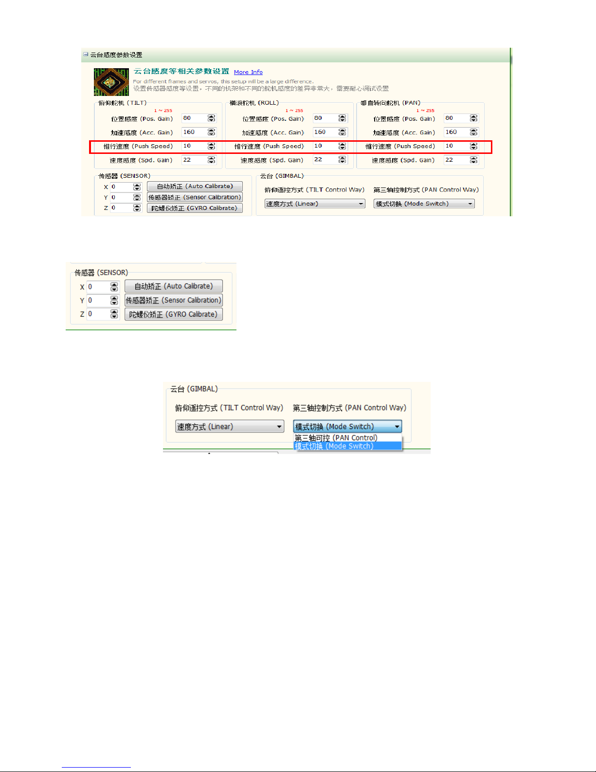
1 Set the “Pan Control Way” to ”Mode Switch”
2 Adjust the 3 motors as below:
Tilt motor
Recover the saved values of Tilt motor’s “Driven Voltage” and click “Burn Params”. It will show “Saved” at the low-left corner in
seconds. Click “disconnect”. Click “Connect” again and click “Read Params”. Make sure the Tilt motor does not shake huge . If
not, please change the “Servo Reverse” and try again.
Roll motor
Recover the saved values of Roll motor’s “Driven Voltage” and click “Burn Params”. It will show “Saved” at the low-left corner
in seconds. Click “disconnect”. Click “Connect” again and click “Read Params”. Make sure the Tilt motor does not shake
huge . If not, please change the “Servo Reverse” and try again.
Pan motor
Recover the saved values of Roll motor’s “Driven Voltage” and click “Burn Params”. It will show “Saved” at the low-left corner
in seconds. Click “disconnect”. Click “Connect” again and click “Read Params”. Make sure the Pan motor does not rotate
continually or motionless If not ,please change the “Servo Reverse”and try again.
If it still does not work after the above steps, please refer to the V2.18 The Firmware Upgrade Guide below.
Appendix 2 The procedure upgrading V1 10/V1 13 to V2 18 or higher
Notice: if the current firmware version is V2.XX then do not read this guide.
Please strictly follow these steps:
1. According to the guide above (Firmware Upgrade), load the “PARAM_UPDATE 20140924 V0.00.Bin” firmware onto the
X-CAM A10-3H and close the firmware upgrade program, and power off the X-CAM A10-3H
2. Power on the X-CAM A10-3H and confirm the red and blue lights are flashing alternately, then power off. (If not flashing,
please try step 1 again.)
3. Load the “A10-3H 20141022 V2.18A Bate.Bin” firmware to the X-CAM A10-3H and close the firmware upgrade program,
and power off the X-CAM A10-3H.
4. Power on the X-CAM A10-3H and observe the gimbal’s behavior, if it is unordered turning try the step 1 and step 2
again. (Step 2 must be executed).
. If the Pan motor is unordered turning, please connect to the X-CAM Gimbal assistant software to change the Pan motor
direction.
6. If the Pan motor is still unordered turning after the step , according to the guide above (Firmware Upgrade), burn the
“A10-3H 20141022 V2.18B Bate.Bin” firmware to the X-CAM A10-3H.
7. If the X-CAM A10-3H still does not work, please feel free to contact X-CAM.
Table of contents
Other X-cam Camera Accessories manuals