X-cam A22-3H User manual

X-CAMA22-3HforSONYNEX53AxisGimbalUserManual
X-CAMA22-3Hhasbeenfinishedwithalltheadjustmentsbeforelaunchthemarket,READYTORUN.
Parameters
Weight: 680g(withoutCamera&Lens)Stabilizationfrequency:5200Hz
Inputvoltage: 11.1v~22.2v(3S~6SLipo) Tilttravel: +-90degree;Rollingtravel:+-45degree
YAW travel: 360degreeswithunlimitedrotation Built-inHDMItoAVModule
AutoPilotSystemsupportingisnotrequired SupportLens: 16mmFixed(Default),16-50mm,16mm+0.75 wideangle
SupportCamera:SONYNEX5Series(Default)、NEX7、BMPCC、SONYA5000、A6000
Accessories
● X-CAMA22-3HGimbalFrameX1
● X-CAMA22-3HMainControllerX1
● USBCableX1
● PPMCableX1
● ThecamerafixedscrewX1
● DampingballsX15
● HDMIToAVCardx1
ConnectionInstructions

PC Software
Connect with PC
Uses the USB adapter to connect with your PC , Normally the Windows can find the driver automatically, you could find the PORT number in
the device Manager
Launch the X-CAM Gimbal Stabilization Module Assistant , choose the correct port number and click CONNECT

BEEP BEEP will be shouted after the connection succeed, the parameters will be read out automatically.
The parameters as below:
1. Gains
Thereare2gains,PositionGainandAccelerationGain
Pos. Gain: Inclined the gimbal to one position slowly and watch the image is horizontal or not, if not just adjust the Pos. Gain.
Acc. Gain: After adjusting the Pos. Gain, Inclined the gimbal to one position quickly and watch the image is horizontal in time, if not just
adjust the Acc. Gain.
Notice: the A10-3H has been finished the adjusting, does not need to adjust again in normally
2. Gimbal Control
TheA10-3Hprovides2waystocontroltheTILT, LinearModeorTrackingMode
LinearMode: PushtheTILTsticktohighorlowfor moving the camera mount to up or down until the stick back to midpoint
Tracking Mode: Push the TILT stick to high or low, the camera mount will follow the stick position.
Push speed: Setup the camera mount moving speed, high value set high speed; low value set low speed.

3. Sensor calibration
AutoCalibration
Ifthescreenframeisnot horizontalpleasedothe“AutoCablibration”as
below:
1. PutaBalanceofbubbleballonthecameraframeandmakethecamera
frameisperpendiculartothegroundby90degree.
2. makethecameraframeishorizontalmanually
3. holdthecameraframeandclick“AutoCablibration”
SensorCalibration
Ifthescreenframeisstill nothorizontalthenyouhavetosetthe“SensorCalibration”,inputtheX,Y,Zoffsetvalueandclick
“SensorCalibration”
GYROCalibration
Makesurethegimbalin quietude and click “GYRO Calibration”, this function will reduce the error which comes from the environment
temperature
Pleasenoticethesesetupmustbesetverycarefully,westronglyrecommendset these parameters with X-CAM supporting.

内置 HDMI 转AV 模块
Initial Settings:
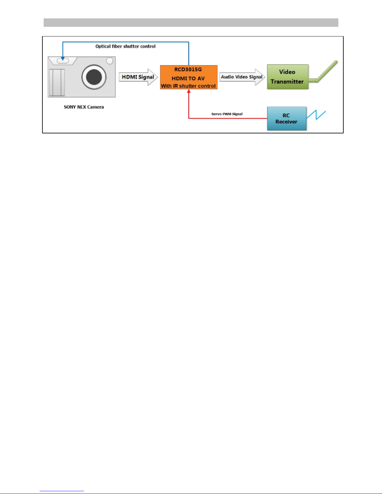
1. Set the camera HDMI output to auto resolution mode.
2. Set the video mode to infrared remote control mode.
3. Connect RCD3015G HDMI converter with the camera, connect the servo cable of shutter controlling with the remote control receiver.
4. Initialize the Camera by pressing the shutter once to get the camera out of review mode.
5. Install the optical fiber on RCD3015G converter, stick the other end of the optical fiber over the window of infrared receiver on the camera.
Important Note:
You need to have a transmitter with a 3 position switch. Map this 3 position switch to a spare channel and connect the servo cable from the
RCD3015G to this channel. If there is no connection, RCD3015G works only as a HDMI to AV converter.
The control of 3-pos switch:
1. Up: Takes a photo (Shutter is pressed)
2. Middle:Shutter is off / Recording is off
3. Down: Video recording is on.
It is very important that the 3-position switch is set in the middle (neutral) position before you power up your RCD3015G converter. ( Note :
RCD3015G powers up when you turn on the camera or power supply of reciever) When the shutter control 3-pos switch is in the
middle(stop/neutral) position, the red LED is on constantly. If there is no signal from the receiver, the red LED flashes 4 times per second, it reminds
customer to check if the receiver is powered and the transmitter is turned on.
Taking Photos:
Toggle the 3-POS switch from middle position to the up position, the camera will start taking photos until the 3-POS switch is toggled to the
middle position. In this mode the red LED flashes 2 times per second.
Recording video:
Toggle the 3-POS switch from the middle position to down position, the camera starts recording a video till the 3-POS switch is toggled to the
middle position. Video is saved in this position. In this mode, the RED LED blinks continuously.
Attention:
There must be a 5 second interval between each operation of the 3-POS switch. e.g. Switching from neutral to recording position and then
back to neutral (recording stop). Please wait for 5 seconds between each mode change. The 5 second interval is required by the camera firmware.
It allows the camera to clear the buffer and safely write the video file to storage. Operating the the 3-POS switch without observing the 5 second
gap will cause the camera to hang and can result in corrupt video files.

Firmwareupgrade
1. Turn off the X-CAM A10-3H
2. Uses the USB cable to connect with your PC, Normally the windows can find the
driver automatically, you will find the PORT number in the device manager.
3. Select the COM port number
4. Open the firmware file ( *.bin )
5. Click “Load and Connect” button
6. Turn on the X-CAM A10-3H, it will upgrade the firmware automatically
Notice: Please do not touch anything and keep the power on during the upgrade, if
the upgrade is break please back to STEP 1 and try again, normally it could be fix
automatically. It will beep 4 times after upgrade and the system will be restarted.
Announcements
1. Do not touch the gimbal during the initialization after turn on, Keep the gimbal in quietude
2. Do not use BEC for the gimbal power, use 3~6S Lipo battery
3. Strongly recommend using 12mm tube to mount the gimbal
4. Make sure the center of gravity of the gimbal is correct before using.
保修及免责声明
The gimbals are covered by one year limited warranty. Please donotdisassembleormodifymechanicalstructureinthe
warranty period. The customized program of the control module is based on the gimbal structure and motors, and all
debugginghasbeencompletedinfactory.Anydirectorindirectdamagescausedbyauserduringuseordamagewillnotbe
coveredbyourwarranty,andX-CAMwillnotcompensatethelossandthecorrespondingliability.
X-CAMdoesnottakeanyresponsibilitytowardanydamageorlossinusingthegimbal.
产品保修登记: http://warranty.x-camtech.com/cgi-bin/XCamWarranty.dll
Table of contents
Other X-cam Camera Accessories manuals