Xanboo XWS10D User manual

Exhibit H: Users Manual
Xanboo
Door Sensor XSC501

WIRELESS
DOOR/WINDOW SENSOR
XWS10D USER’S GUIDE
APPROVALS ///
FCC ID NUMBER: OU4-XSC501 / IC: 4576A-XSC501
STANDARDS
93/68/EEC, 89/336/EEC, BS EN 50082-1:1992, 73/23/EEC, EN60950:1992 CE
INSTRUCTION TO THE USERS (IF DEVICE DOES NOT CONTAIN A DIGITAL DEVICE)
The user is cautioned that changes or modifications not expressly approved by the party responsible for compliance could void the user’s
authority to operate this equipment.
INSTRUCTION TO THE USER (IF DEVICE CONTAINS A DIGITAL DEVICE)
This equipment has been tested and found to comply with the limits for a class B digital device, pursuant to part 15 of the FCC Rules.
These limits are designed to provide reasonable protection against harmful interference in a residential installation. This equipment
generates, uses and can radiate radio frequency energy and if not installed and used in accordance with the instructions, may cause
harmful interference to radio communications. However, there is no guarantee that interferences will not occur in a particular installation.
If this equipment does cause harmful interference to radio or television reception, which can be determined by turning the equipment off
and on, the user is encouraged to try to correct the interference by one or more of the following measures:
• Reorient or relocate the receiving antenna.
• Increase the separation between the equipment and receiver.
• Connect the equipment into an outlet on a circuit different from that to which the receiver is connected.
• Consult the dealer or an experienced radio/TV technician for help.
The term “IC:” before the certification/registration number only signifies that the Industry Canada technical specifications were met.
Operation is subject to the following two conditions: (1) this device may not cause interference, and (2) this device must accept any
interference, including interference that may cause undesired operation of the device.
DRILLING TEMPLATE FOR WALL MOUNTING SENSOR(S) ///
DRILL HOLES IN
THESE POSITIONS

PRODUCT DESCRIPTION ///
The Xanboo™Door/Window Sensor allows for convenient placement. Using a magnetic
force field created between the sensor and a magnetic contact you can secure household doors,
office doors, file cabinets or windows.
PACKAGE CONTENTS ///
■(1) Door/Window Sensor
■(1) Magnetic Contact
■(1) Hardware Kit
■(1) Installation Guide
CONNECTING TO THE GATEWAY ///
DISCOVERING NEW DEVICES
In order for the Gateway to control Xanboo devices such as cameras and sensors, each device must be
registered with the Gateway . The iG3 Gateway establishes a “secure wireless network” between itself
and all discovered Xanboo devices. The Gateway can only control devices that it has discovered.
New devices can be discovered at any time:
A. Log into the iG3 using ‘XANASSIST’
B. Click on the ‘DISCOVERY’ menu option
C. Click the ‘START DISCOVERY’ menu item, on the left,
to begin discovery for your Door/Window Sensor.
D. At this time, using a paper clip, press the
‘DISCOVERY’ button on the back of your Door/
Window Sensor. The light on the device will turn
green when the Gateway has discovered it properly.
NOTE: After a brief period, the LED will turn off. The LED is only Green when transmitting. The LED is
not 'lit' during sleep mode (waiting for the next time to transmit a signal).
I 2
DOOR/WINDOW SENSOR MAGNETIC CONTACT HARDWARE KIT
DEVICE DISCOVERY
BUTTON
MOUNTING HOLE
MOUNTING HOLE
E. Go back to your PC and confirm that the device has been discovered and displayed.
F. Click on the ‘STOP DISCOVERY’ menu option when you are finished discovering all of your devices.
G. The Gateway and devices are now ready to be used.
ADDITIONAL NOTES
A. This page will refresh every 10 seconds to show newly discovered devices. You may have to
wait for a refresh to see the device listed.
B. The Gateway will automatically stop discovery after 10 minutes or if you browse off the page
C. New devices can only be discovered when the Gateway has an active Internet connection
(ie. your Gateway is connected to the internet).
MOUNTING ///
The Xanboo™Door/Window Sensor is constructed of UV resistant ABS plastic allowing for
indoor or sheltered outdoor use. The Sensor works by creating a magnetic field between the Sensor
base and the magnetic contact. When there is a change in status, either opening or closing, the Sensor
will trigger an event to the Gateway. The spacing between the Sensor and the contact should be
between 1/10 inch and .5 inch.
NOTE: The Door/Window Sensor cannot be used on metal doors, metal door frames or metal objects.
1. Peel the paper strip from the double-sided tape located on the back of the Sensor.
You can also mount the sensor more securely using the screws in the hardware kit.
Using the drilling template on the back of the instruction guide, drill two small holes for
the screws. Affix the screws to one side of the object (typically the “stationary” side) leaving
1/16“ space between the screw head and the object,
2. Mount the Sensor onto the screws and slide down to lock into place
3. The magnetic contact should now be placed on the other side of the object (typically the
side that moves)
SETUP WIZARD DEVICE DISCOVERY (IN PROGRESS) PAGE

3 4
This device complies with part 15 of the FCC rules. Operation is subject to the
following two conditions: (1) this device may not cause harmful interference,
and (2) this device must accept any interference received, including
interference that may cause undesired operation.
WARRANTY ///
This product has a one year manufacturer's warranty which covers parts and
SYMPTOM
Events are not
triggered
REMEDIES
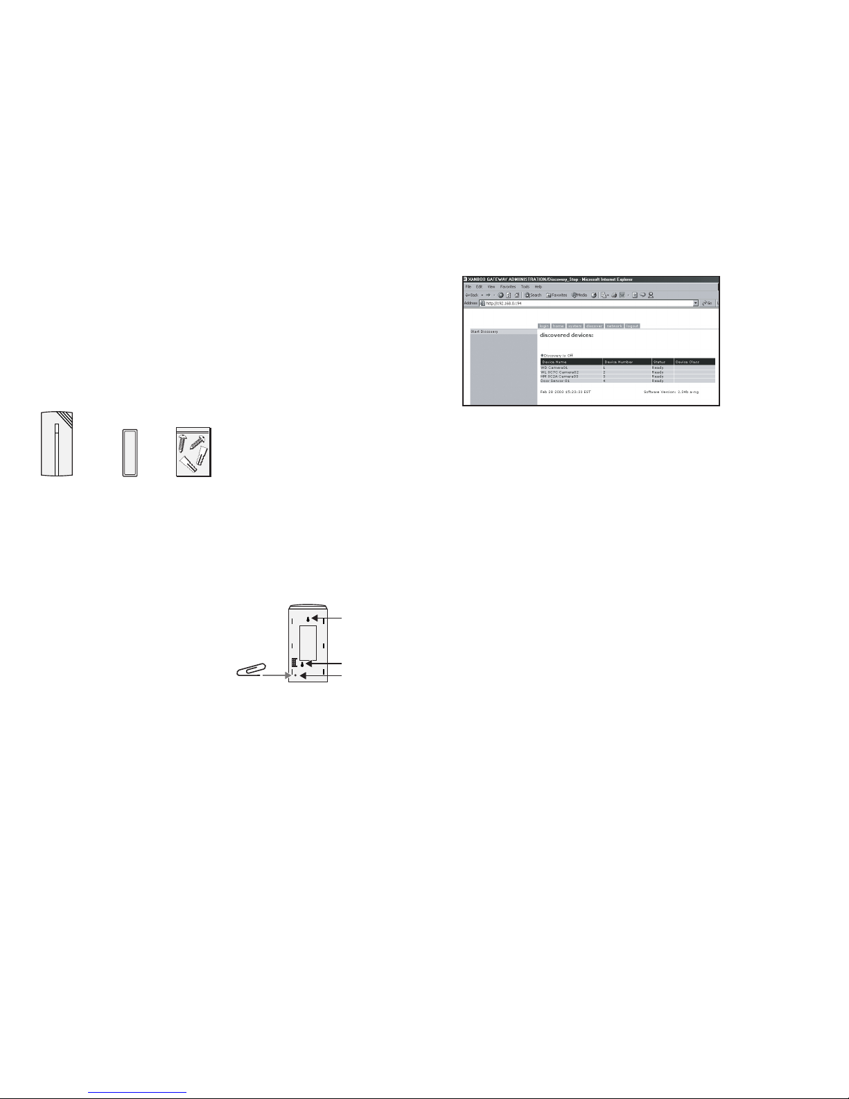
1.Check to make sure that the sensor has been registered properly with the gateway.
2.Check to make sure that the gateway is currently connected to the internet
and is online.
3. Check to make sure the spacing between the contact and the sensor is
between 1/10” and 1”
4. Check to make sure that you have the proper settings configured for
the sensor. The sensor can be configured so that it can send an event when
the contacts are closed or when they are opened.
5. Ensure that the sensor and contact are not placed on metal or magnetic objects
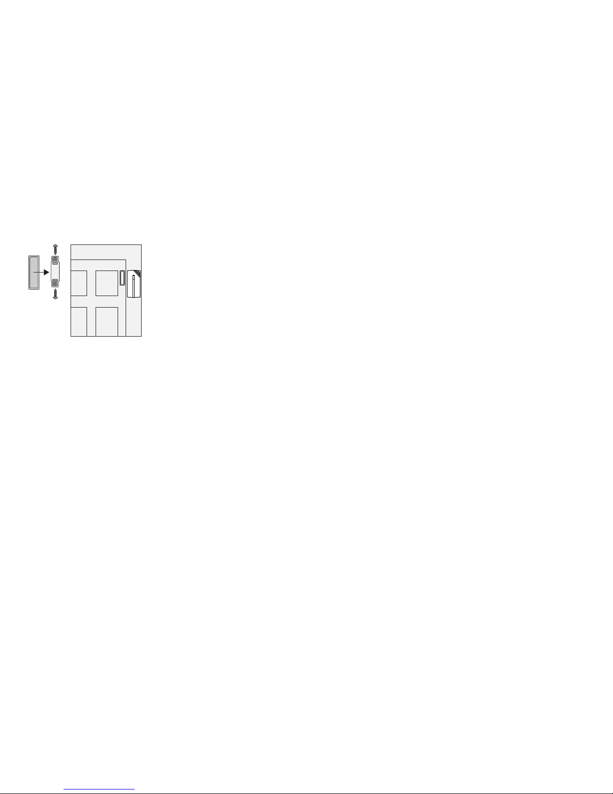
4. Either peel the paper strip from the double-sided tape located on the back of the contact
or you can more securely attach it using screws in the hardware kit. Remove the cover from
the contact and insert the screws through the holes on the top and bottom of the contact.
5. Make sure the magnetic contact aligns with the top of the Sensor base on either the left
or right sides of the base.
HELPFUL HINTS ///
The Xanboo™Door/Window Sensor is suitable for indoor and outdoor use. Please bear in mind the
following points when choosing a mounting position:
■Xanboo™Door/Window Sensor cannot be mounted on metal doors, metal door frames
or metal objects.
■Be sure to use 2-“AAA” alkaline batteries from a reliable manufacturer. Currently the sensor
does not support rechargeable NiCad or NiMH batteries. However, the sensor does have
power saving functionality.
■You may want to periodically use the ‘test’ button to ensure the gateway can “hear” the sensor.
FAQ’S ///
HOW FAR AWAY CAN THE SENSOR BE PLACED FROM THE GATEWAY?
Typically 60-80 feet.
CAN I PLACE THE SENSOR IN A DIFFERENT ROOM FROM THE GATEWAY?
Yes, the sensor and gateway use radio frequencies to communicate with each other.
These frequencies can go through objects like walls, ceilings and floors
HOW LONG WILL THE BATTERY LAST?
The battery is expected to last up to 12 months. This will depend on actual use and how often
the sensor is triggered. The Xanboo Door/Window Sensor includes battery saving features that make
the Sensor “hibernate” when there is no activity. It ‘wakes-up’ when the sensor is triggered
HOW MANY SENSORS CAN I REGISTER WITH MY GATEWAY?
The gateway can support up to 8 sensors.
THE LIGHT ON THE SENSOR IS NOT ON?
This indicates that the sensor has gone into hibernation mode. It will wake up when the sensor is triggered.
TECHNICAL SPECS ///
■Attaches to any flat surface
■Operates on 2-AAA Alkaline batteries
■LED indicator when sensor is triggered
■Test/Discover button
■Magnetic contacts
■Key-fob ready for enabling encrypted communications
Typical Range Outdoors: 250 feet
Typical Range Indoors: 60 feet
Frequency Range: 418-433 MHz
WARRANTY ///
This product has a one year manufacturer’s warranty which covers parts and labor only. In the unlikely
event that you encounter a problem, the unit should be returned to the place of purchase.
TROUBLE SHOOTING ///
SYMPTOM
LED does not
light up
Gateway does not
recognize the
sensor during
discovery
Sensor continually
sends an event
REMEDIES
1. Be sure the batteries are properly inserted with the correct polarity.
2. Be sure you are using fully charged batteries
1. Ensure sensor has correct power
2. Position the sensor in closer proximity to the gateway and try again.
3.Check to make sure there is no other wireless devices interfering with
the sensor. The sensor transmits on the 418 MHz or 433 MHz frequencies
1.Check to make sure that you have the proper settings configured for
the sensor. The sensor can be configured so that it can send an event
when the contacts are closed or when they are opened.
MOUNTING AND POSITIONING OF MAGNETIC CONTACT
This manual suits for next models
1
Table of contents
Popular Accessories manuals by other brands

DH Instruments
DH Instruments RUBBER SHOE ACCESSORY - SCHEMA P-N 400202 manual

HELLA Aglaia
HELLA Aglaia APS-90 Installation and configuration manual

IFM
IFM MFH operating instructions

Seametrics
Seametrics DO2 instructions

QOLSYS
QOLSYS IQ PANEL installation manual

Detcon
Detcon SmartWireless CX Operator's installation and instruction manual