Xandex 340-7110 User manual

820-0332 Micro-Z Small Dot Inking System Installation and Operation Rev A, September, 2022
MICRO-Z SMALL DOT PNEUMATIC INKER
INSTALLATION AND OPERATION MANUAL
Models 340-7110 and 340-7120
820-0332
Revision
A
September, 2022
340-7110 Manual Micro-Z Inker
IMPORTANT OPERATION NOTICE!
The Model 350-0027 Micro-Z Small Dot Pneumatic Controller
has two (2) air inputs. Each is designed to operate at 80
±
5
PSI.
FAILURE TO SET BOTH AIR REGULATORS PROVIDING AIR TO
THE CONTROLLER AT 80 PSI WILL RESULT IN INCONSISTENT
340-7120 Motorized Micro-Z Inker

2 820-0332
SERVICE AND SUPPORT INFORMATION
Telephone: (707) 763-7799
OR (800) 767-9543
1360 Redwood Way, Suite A
Petaluma, CA 94954 USA
FAX: (707) 763-2631
Internet: www.xandexsemi.com
Email: [email protected]
International Distributors
China
PREMTEK TECHNOLOGY INC. (Shanghai)
RM 1201,
NO.1077
ZuChongZhi Rd
Zhang Jiang
Hi-Tech Park
PuDong New Area
Shanghai, China 201203
Telephone: 86
-21-5027-5859
Email:
Website: www.premtek.com.tw
Japan
HUGLE ELECTRONICS, INC.
4
-5-7 Iidabashi,
Chiyoda
-Ku
Tokyo, Japan 102
-0072
Telephone: (81) 3.3263.6661
Fax: (
81) 3.3263.6668
Email:
Website: www.hugle.co.jp
Korea
HUGLE ELECTRONICS, INC.
Br. Office: 2FL Hugle Bldg.
86
-14 Garak-Dong, Songpa-Ku
Seoul, Korea 138
-803
Telephone: +82 (02) 431
-7477
Fax: +82 (02) 449
-6295
Email:
Website:www.hugle.co.kr
Taiwan
PREMTEK INTERNATIONAL
4F, No. 47, Lane 2, Kuang
-Fu Road
Sec 2, Hsinchu City
Taiwan R.O.C.
Telephone: (886) 35.722000
Fax: (886) 35.725000
Email:
Website:
www.premtek.com.tw

820-0332 3
IMPORTANT OPERATION INFORMATION!
The Model 350-0027 Micro-Z Small Dot Pneumatic Controller requires two
independent filtered air inputs, one for the Inker Shuttle mechanism and one
for the DM-2 Pneumatic Ink Cartridge. Each input is designed to operate at
80 ±5 PSI.
FAILURE TO SET THE REGULATORS PROVIDING AIR TO THE
CONTROLLER AT 80 PSI WILL RESULT IN INCONSISTENT SYSTEM
OPERATION!
For more information contact Xandex Customer Service at (707) 763-7799 or Toll
Free in the U.S at (800) 767-9543, FAX (707) 763-2631, or visit us on the Internet at
www.xandexsemi.com
LIFT KNOB TO UNLOCK,
TURN KNOB TO ADJUST
PRESSURE SETTING AND
PUSH KNOB DOWN TO LOCK.
SET AIR PRESSURE TO 80 PSI

4 820-0332
SAFETY INFORMATION
Safety and Hazard identification symbols used in this document are intended to be
compliant with ANSI/NEMA Z 535.6 2006. The table below lists the symbols used
in this document along with a description of each type of safety hazard. Failure to
observe identified safety risks may result in serious injury or death.
Safety and Hazard Identification Symbols
SYMBOL DESCRIPTION
DANGER = Indicates a hazardous situation which, if
not avoided, will result in death or serious injury
WARNING = Indicates a hazardous situation which,
if not avoided, could result in death or serious injury.
CAUTION = Indicates a hazardous situation which, if
not avoided, could result in minor or moderate
injury.
NOTICE = Indicates a practice that is not related to
personal injury but may cause damage to equipment
or property.
Use this product only in the manner described in this
manual. If the equipment is used in a manner not
specified by the manufacturer, the protection provided
by the equipment may be impaired.
Install the pneumatic controller in a location that is
easily accessible to the operator. The ON/OFF switch
is the pneumatic controller’s main disconnecting device
and must be easily accessible at all times.
For your safety, the AC power cord set provided with
your product has a grounded plug. Always use the
power cord with a properly grounded wall outlet, to
avoid the risk of electrical shock.
Do not operate this product with a damaged AC power
cord set. If the AC power cord set is damaged in any
manner, replace it immediately. Damaged cords may
result in user exposure to hazards.
DANGER
WARNING
CAUTION
WARNING
WARNING
WARNING
WARNING

820-0332 5
The power cord set received with the product meets the
requirements for use in the country where you
purchased the equipment. Use only the power cord
provided with the unit or an authorized replacement
power cord from Xandex Inc. or an approved Xandex
distributor. Use of an inadequately rated power cord may
result in shock or injury.
Do not operate this product with a damaged DC power
supply. If the DC power supply is damaged in any
manner, replace it immediately. A damaged DC power
supply may result in user exposure to hazards.
The DC power supply received with the product meets
the requirements for use in the country where you
purchased the equipment. Use only the DC power supply
provided with the unit or an authorized replacement
power supply from Xandex Inc. or an approved Xandex
distributor. Use of an inadequately rated power supply
may result in shock or injury.
WARNING
WARNING
WARNING

6 820-0332
CONTROLLER / INKER REDESIGN
Re-design Overview
The Xandex DieMark®350-0027 Micro-Z Small Dot Pneumatic Controller and the
X7110 Manual and X7120 Motorized Micro-Z Inker Assemblies represent a new design
that incorporates several changes that make it unique to the inker assembly model(s)
designed for use with the Micro-Z Pneumatic Controller. (This controller cannot be used
with other DieMark inker assemblies)
The design changes focus on features specific to repeatable, reliable small (5 mil and
smaller) ink dot production, including:
1. Separate regulated Controller air inputs for the Cartridge Valve and the Shuttle
Valve to isolate dot production from even minor changes in air pressure that may
occur when the Cartridge and Shuttle valves share a single air input.
2. Modified controller firmware to optimize the cartridge valve on time for smaller
dot settings.
3. A new Precision pneumatic shuttle design that reduces friction between moving
parts and eliminates potential vibration related parts movement for more accurate,
repeatable dot placement.
4. An orifice has been added to the shuttle’s air signal input tubing that acts to
dampen the shuttle end of stroke and dramatically reduce the shock vibration
present in previous pneumatic shuttle designs.
5. Manual and Motorized Micro-Z Models: Changes to the Inker Assembly also
include a rigid “uni-body” design that eliminates multiple points of movement
compared to previous pneumatic inker models.
6. Manual Micro-Z Model” manual Z height adjustment system is much more
accurate than previous manual DieMark inker models. Accuracy in Z adjustment
is critical in obtaining uniform small ink dots.
7. Motorized Micro-Z Model: A motorized version of the Manual Micro-Z Inker
Assembly is available to provide extremely accurate Z adjustment with push
button controls. The Motorized Micro-Z inker provides Z adjustment of 0.00005
inches per actuation in Micro-Z mode.
Please contact Xandex Customer Service with any questions regarding this design change
or any other feature of your Xandex DieMark Inking System.
Intentionally left blank

820-0332 7
TABLE OF CONTENTS
Re-design Overview........................................................................................................ 6
Introduction.................................................................................................. 1-1
Theory of Operation..................................................................................................... 1-1
System Overview.......................................................................................... 2-1
Manual Micro-Z Component Connection.................................................................... 2-1
Motorized Micro-Z Component Connection ............................................................... 2-2
Installation.................................................................................................... 3-1
X7110 and X 7120 MICRO-Z Inker Installation........................................................ 3-1
Controller Installation .................................................................................................. 3-3
System Operation......................................................................................... 4-1
Controller Operation .................................................................................................... 4-1
Ink Cartridge ................................................................................................................ 4-6
Cartridge Type Label Color Code................................................................................ 4-6
Ink Cartridge Labeling................................................................................................. 4-7
Cartridge Preparation................................................................................................... 4-8
Cartridge Installation ................................................................................................... 4-8
Cartridge Priming....................................................................................................... 4-10
Manual Micro-Z Inker Assembly Setup .................................................................... 4-10
Motorized Micro-Z Inker Assembly Setup................................................................ 4-12
Cartridge Priming Tips .............................................................................................. 4-15
Ink ................................................................................................................. 5-1
General Information..................................................................................................... 5-1
Ink Curing .................................................................................................................... 5-2
General Notes on Ink Curing ....................................................................................... 5-2
Ink Curing Guidelines.................................................................................................. 5-3
Ink Removal Information............................................................................................. 5-4
Maintenance & Troubleshooting................................................................ 6-1
Ink Troubleshooting..................................................................................................... 6-1
Inker Troubleshooting.................................................................................................. 6-3
Micro-Z Shuttle Maintenance...................................................................................... 6-4

8 820-0332
Controller Troubleshooting.......................................................................................... 6-5
Controller Preventive Maintenance ............................................................................. 6-6
System Specifications................................................................................... 7-1
DC Power Supply Requirements ................................................................................. 7-1
Pneumatic Controller Specifications............................................................................ 7-1
Inker Specifications ..................................................................................................... 7-2
Ink Cartridge Specifications ........................................................................................ 7-3
Cartridge Availability .................................................................................................. 7-3
Dot Size Guidelines in Mils (0.001 inch) .................................................................... 7-4
Dot Size Guidelines in Microns................................................................................... 7-5
Inker Warranty............................................................................................................. 7-6
System Drawings ......................................................................................................... 7-7

820-0332 1-1
Introduction
Theory of Operation
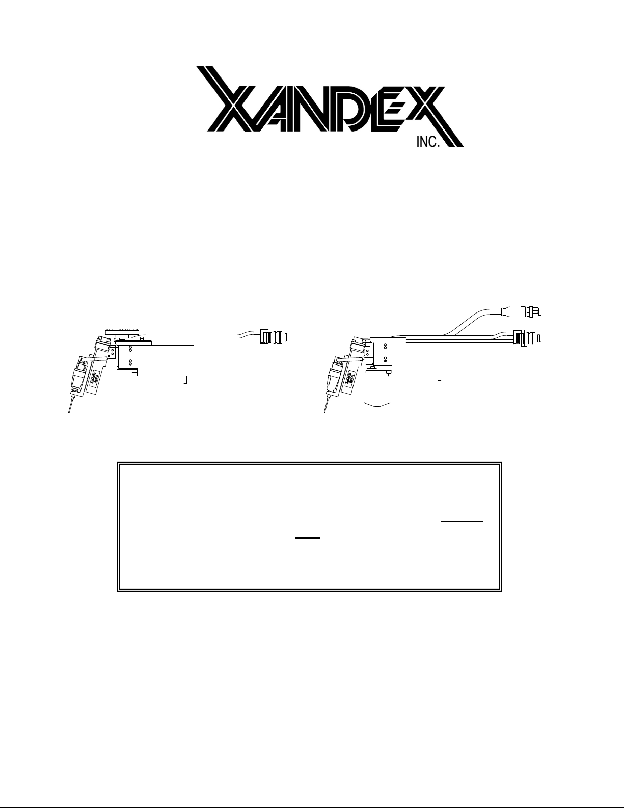
The X7110 Manual and X7120 Motorized
Micro-Z pneumatic inkers are designed for
use in cabled in-line and off-line inking. The
innovative Micro-Z design combines op-
erator friendly Micro-Z movement ca-
pability in both Manual or Motorized
models which provides fast, precise Z
adjustment, with a dual air regulation system
to produce small ink dots of 5 mil or less
with consistent geometry and extreme
repeatability.
The Micro-Z series inker also incorporates
the convenience of a new A4 model
DieMarkdisposable ink cartridge for the
ultimate small dot inking solution.
Ink dots are deposited via pneumatic actuation of the inker shuttle mechanism and a
simultaneous pulse of air into the cartridge reservoir. There is no filament and no direct
contact with the wafer surface. A prober signal to the controller initiates the inking
sequence, actuating the shuttle mechanism downward and sending an air pulse to the
cartridge.
As the shuttle extends to the downward position, the air pulse to the cartridge forces ink
out of the cartridge barrel and forms a drop at the end of the needle tip. When the shuttle
is at its lowest position, the drop makes contact with the wafer surface and forms a dot.
After several milliseconds the shuttle returns to the normal position. After completion of
each dot, slightly lower pressure is developed in the cartridge by the closure of the valve,
causing the ink to back up into the cartridge reservoir, preventing dripping.
The dot size is determined by cartridge air pulse duration. Adjust the controller setting to
change the dot size - without changing the cartridge. Pneumatic cartridges are factory
tuned, ensuring consistent dots and contain 40% more ink than standard DieMark
filament ink cartridges.
Thank you for selecting Xandex as your inking choice. Please spend a few minutes
familiarizing yourself with the unit. Most questions you may have will be answered in this
manual. If you would like further assistance, please contact your local Xandex distributor
or call us at (707) 763-7799 or Toll Free in the U.S: (800) 767-9543. FAX (707) 763-
2631. For more information about Xandex and our complete line of quality inking and
interfacing products, visit us on the Internet at www.xandexsemi.com or email: us at
X7110 Micro-Z Manual
X7120 Micro-Z Motorized

1-2 820-0332
This page is intentionally left blank.

820-0332 2-1
SUPPLY
AIR
SUPPLY
AIR
T
O
P
R
O
B
E
R
System Overview
Manual Micro-Z Component Connection
1. Regulator Assembly (Qty. 2)
Part No. 220-0076
2. Air Hose Regulator-to-
Controller (Qty. 2)
Part No. 210-2001
3. Micro-Z Small Dot Pneumatic
Controller Part No. 350-0027**
4. Micro-Z Manual Pneumatic
Inker Assembly Part No. 320-
7110
A. Pneumatic Shuttle Part
No. 316-0010
B. Inker Mounting Plate Part
No. 120-0019 (340-7110-
02 for KLA only)
5. Cable/Connector Assembly*
Type C +none #210-0113
Order Set 340-7110-05
Type P8-C for TEL #210-0120
Order Set 340-7110-04
Type J-C for TSK / Accretech
#210-0114
Order Set 340-7110-03
Type C-C for KLA #210-0110
Order Set 340-7110-02
Type A-C for EG #210-0109
Order Set 340-7110-01
6. Cartridge Opening Tool Part
No. 200-0001
7. 24VDC Power Supply Part No.
220-0078
8. **A. AC Power Cord (USA)
Part No. 158-0051 OR
**B. AC Power Cord (Europe)
Part No. 158-0407 OR
**C. AC Power Cord (UK)
Part No. 158-0408
**D. AC Power Cord
(PSE-Japan)
Part No. 158-0727
*One cable type supplied and is specified
based on part number tabulation.
**One AC power cord is shipped with each
set and must be specified at ordering.
A
B
C
D
A
B
Objects not to scale.

2-2 820-0332
SUPPLY
AIR
T
O
P
R
O
B
E
R
SUPPLY
AIR
Motorized Micro-Z Component Connection
1. Regulator Assembly (Qty. 2)
Part No. 220-0076
2. Air Hose Regulator-to-
Controller (Qty. 2)
Part No. 210-2001
3. Micro-Z Pneumatic Controller
Part No. 350-0027**
4. Micro-Z Pneumatic Inker
Assembly Part No. 320-7120
A. Precision Pneumatic
Shuttle Part No. 316-
0010
B. Inker Mounting Plate
Part No. 120-0019
(340-7120-02 for KLA
only)
5. Cable/Connector Assembly*
Type C +none #210-0113
Order Set 340-7120-05
Type P8-C for TEL #210-0120
Order Set 340-7120-04
Type J-C for TSK / Accretech
#210-0114
Order Set 340-7120-03
Type C-C for KLA #210-0110
Order Set 340-7120-02
Type A-C for EG #210-0109
Order Set 340-7120-01
6. Cartridge Opening Tool Part
No. 200-0001
7. 24VDC Power Supply Part No.
220-0078
8. **A. AC Power Cord (USA)
Part No. 158-0051 OR
**B. AC Power Cord (Europe)
Part No. 158-0407 OR
**C. AC Power Cord (UK)
Part No. 158-0408
**D. AC Power Cord
(PSE-Japan)
Part No. 158-0727
*One cable type supplied and is specified
based on part number tabulation.
**One power cord is shipped with each set
and must be specified at ordering.
A
B
C
D
A
B
Objects not to scale.

820-0332 3-1
Installation
X7110 and X 7120 MICRO-Z Inker Installation
The X7120 Motorized and X7110 Manual Micro-Z pneumatic inkers are for use with
wafer probing and wafer inspection equipment from multiple OEMs. Both Manual and
Motorized models are installed using two 4-40 x 1.25" Shoulder Head Cap Screws
(SHCS)
1. If you are currently using another inker, remove it from the prober/ equipment.
Move the chuck/wafer from underneath the inker when
installing inker to prevent damage.
2. Install the inker base onto the prober using the two (2) supplied 4-40 x 1.25"
SHCS. Torque to 8.0 inch-pounds (in-lbs).
X7110 Manual Micro-Z Inker Assembly
X7110 MANUAL
INKER BASE
ASSEMBLY
PNEUMATIC
SHUTTLE
ASSEMBLY
CONTROLLER-TO-
SHUTTLE AIR HOSE:
CONNECT TO LARGE
“SHUTTLE” PORT
CARTRIDGE FITTING
(RED HOSE)
MICRO-Z
ADJUSTMENT
DIAL
2X 4-40 x 1.25"
INSTALLATION
SCREWS

X7110 and X 7120 MICRO-Z Inker Installation Installation
3-2 820-0332
X7120 Motorized Micro-Z Inker Assembly
3. Error! Not a valid bookmark self-reference.” portion of this Installation
Section (3) and install the pneumatic controller per instructions for your
application.
4. Proceed to Chapter 4. System Operation for ink cartridge installation, inker
setup, alignment, and controller operation instructions.
Do not install an ink cartridge on the inker until after the
inker is installed on the prober or damage to the ink
cartridge may occur.
X7120 MOTORIZED
INKER BASE
ASSEMBLY
PNEUMATIC
SHUTTLE
ASSEMBLY
CONTROLLER-TO-
SHUTTLE AIR HOSE:
CONNECT TO LARGE
“SHUTTLE” PORT
MOTOR CABLE
CONNECTOR TO
CONTROLLER:
CONNECT TO
“MOTOR” TERMINAL
CARTRIDGE
FITTING
(RED HOSE)
MICRO-Z
ADJUSTMENT
MOTOR
2X 4-40 x 1.25"
INSTALLATION
SCREWS

Installation Controller Installation
820-0332
3-3
Controller Installation
Regulator Assembly and Installation
The Micro-Z Small Dot Controller requires two regulated air inputs. The supplied air
hoses connecting the regulators to the controller are 6 ft (182 cm) in length. Install the two
regulators close enough to the controller location that ensures free air flow. Make sure the
air hoses are not overextended, twisted, bent or kinked. Install each regulator as follows;
1. Remove the bracket from the regulator/filter assembly by removing the plastic
retaining nut. Mount the regulator/filter bracket in a convenient location
(mounting screws are not supplied). Re-mount the regulator to the bracket with
the supplied nut after the bracket is installed.
The Model 350-0027 Small Dot Controller is designed to
operate at 80 ± 5 PSI. FAILURE TO SET THE
REGULATORS PROVIDING AIR INPUT TO THE
CONTROLLER AT 80 PSI WILL RESULT IN
INCONSISTENT SYSTEM PERFORMANCE!
AIR FLOW ARROW
LOCATED ON ONE
SIDE ONLY
(BEHIND GAUGE)
INSTALL
REGULATOR - TO-
CONTROLLER AIR
HOSE HERE
(P/N 210-2001)
REGULATOR/FILTER
ASSEMBLY
P/N 220-0076
LIFT KNOB TO UNLOCK,
TURN KNOB TO ADJUST
PRESSURE SETTING AND
PUSH KNOB DOWN TO LOCK.
PLASTIC NUT
RETAINS BRACKET
MOUNTING BRACKET

Controller Installation Installation
3-4 820-0332
2. Lift the regulator adjustment knob and turn counterclockwise until it stops to
shut off the regulator air output. Do this on both regulators.
3. Install 1/4 O.D. x 0.170 I.D. polyethylene tubing (not supplied) to the main air
source and then connect to the input fitting on the regulators. (The left side
when facing the gauge.)
4. Connect the regulator-to-pneumatic controller air hoses(P/N 210-2001
supplied) to the output fittingson the regulators. (The right-side fittings when
facing the gauge.)
5. Plug one of the regulator-to-controller air hosesinto the AIR IN port labeled
“SHUTTLE” on the rear of controller.
6. Plug the 2nd regulator-to-controller air hose into the AIR IN port labeled
“CART” on the rear of controller.
Note: The air hose connectors are spring locked. If the air hose connectors do not insert
easily, make sure the spring lock is in the open position by pushing the metal snap-
lock down until it clicks.
7. Turn on the main air and adjust the regulator until it reads 80 ±5 PSI on both
regulator dials. To make regulator adjustments, pull up on the knob on the top
of the regulator to unlock, then rotate the knob clockwise to increase or
counterclockwise to decrease. Push down on the knob after adjustment to lock
it into position.
8. Check all connections for air leaks. If required, turn off the main air and make
necessary adjustments / repairs.
9. Install the cable/connector cable to the inker port on the prober and the
"PROBER"connector on the rear of the controller unit.
10. Move the toggle switch on front of the controller to "RUN" (mid) position.
11. Connect the fitting on the controller-to-shuttle air hose into the pneumatic
connection on the rear of the pneumatic controller labeled "SHUTTLE". (The
large port in the top left hand corner on the controller back panel: NOT the port
with the same name in the “Air In” section below the large port.)
12. Motorized Micro-Z inker only: Route the cable and connector from the inker
to the mating jack on the rear of the controller labeled "MOTOR" and connect.
If you are connecting a Manual Micro-Z inker, go to step 13 and connect the
power supply.
13. Install the AC power cord into the back of the power supply. Connect the power
supply cord to the 24V-.84A socket on the back of the controller. Plug the AC
power cord into a 100-240 VAC supply outlet. Turn the ON/OFF switch on the

Installation Controller Installation
820-0332
3-5
front of the controller to ON. At this point, the "INK ON" LED and the
"STATUS" LED will flash faintly once, and the “POWER” LED will stay on.
14. This completes Inker and Controller installation. Proceed to Section 4 “System
Operation” for ink cartridge installation, inker setup, alignment, and controller
operation instructions.
Note: The standard controller-to-shuttle air hose supplied by Xandex is 3 feet (91.44 cm)
long. The length of this air hose is a critical design specification. If a longer air
hose is required, consult Xandex Product Support for mitigation information.
CONNECT INKER ASSEMBLY
CONTROLLER -TO-SHUTTLE
AIR HOSE HERE
CONNECT CABLE/
CONNECT
ASSEMBLY
HERE
CONNECT #1
REGULATOR-TO-
CONTROLLER AIR
HOSE HERE
CONNECT 24V DC
POWER SUPPLY HERE
OPTIONAL FOOT
SWITCH PORT
MOTORIZED INKER
ONLY: CONNECT
INKER MOTOR
CABLE
CONNECTOR HERE
CONNECT #2
REGULATOR-TO-
CONTROLLER AIR
HOSE HERE
PUFF PULSE SELECTOR SWITCH:
PLACE IN A4 M
ODE TO USE A4
CARTRIDGE
PLACE IN A5-
A8 MODE TO USE A5,
A6, OR A8 CARTRIDGE

Controller Installation Installation
3-6 820-0332
This page is intentionally left blank

820-0332 4-1
System Operation
Controller Operation
ON-OFF Switch:
The ON/OFF switch turns power to the
controller ON and OFF. The POWER
LED will light when power is turned
ON.
Programable Thumbwheel Counter
Individual thumbwheel settings are
available to monitor the number of
Dots placed by an ink cartridge (Dots
X 1000). These three thumbwheels
can be set to any number of dots
between 1,000 and 999,000. A red
"STATUS" LED will be illuminated,
and an audible alarm will sound when
the programmed limit is exceeded.
For example, if you select 30,000 dots
(turning the "DOTS X 1000"
thumbwheel to 30) the "STATUS" LED will light when 30,000 dots have been deposited.
Upon installation of a new ink cartridge, it is recommended that the thumbwheels be reset
to alert the operator when a cartridge is nearing replacement. The “DOTS X 1000” setting
is programmed by using the RESET button. See RESET button for programming the
“DOTS X1000” setpoint.
Install the pneumatic controller in a location that is easily
accessible to the operator. The ON/OFF switch is the
pneumatic controller’s main power disconnect device and
must always be easily accessible.
WARNING

Controller Operation System Operation
820-0332
4-2
Reset Button:
A "RESET" button is located to the
right of the thumbwheels for resetting
the counters in the microprocessor.
When the "RESET" button is
depressed once, the "INK ON" LED
will flash for 5 seconds. If it is pressed
a second time within 5 seconds, it will
"read" the setting on the Dots X 1000
thumbwheel counter and load those
values into the microprocessor. If the
"RESET" button is not pressed a
second time and the 10-second flash
time is exceeded, the "INK ON" LED will stop flashing and the current set points and
internal counts will not be changed.
The "RESET" button is also used to enter the diagnostic mode when power is applied to
the controller with the "RESET" button depressed.
Audible Alarm: An audible alarm is activated, along with the "STATUS" LED, whenever
the "DOTS X 1000" thumbwheel setting has been reached. The alarm is silenced and reset
by pausing the prober, resetting the "DOTS X 1000" thumbwheels if desired and depressing
the "RESET" button twice within five seconds.
Digital Dot Counter:
A separate LCD dot counter is located
on the front panel above the
thumbwheels. This counter has an
internal Lithium battery with a
nominal life of 7 years, and an integral
reset button. Pressing the small reset
button below the LCD window will
reset the counter display only. It will
have no effect on the counter circuits
within the microprocessor. Upon
installation of a new ink cartridge, it is
recommended that the counter be reset
to accurately record the numbers of
dots produced by that cartridge.
This manual suits for next models
1
Table of contents
Popular Paint Sprayer manuals by other brands

Fimco
Fimco LSS-240 owner's manual

Litheli
Litheli U1PR210000 Operator's manual

swissmex
swissmex SP12 Series Operator's manual

WAGNER
WAGNER W 400 Translation of the original operating instructions

Seiwa
Seiwa S 101E instruction manual

Graco
Graco Fuller O'brien Paints Pro 501st Series Instructions-parts list