XBody TRAINING SUIT User manual

XBODY TRAINING SUIT
USER MANUAL

User Manual
Version: 1.1
Page: 2 / 29
TABLE OF CONTENTS
1Preface 3
2General description 4
2.1 Intended Use 4
2.2 Unpacking –Device and Accessories 4
3Safety Guide 5
3.1 Where never to apply the electrodes 5
3.2 Safety regulations 5
3.3 Precautions 5
3.4 Training advices 6
4Preparing for the first use 7
4.1 The training suit 7
4.2 Sizes of training suits and other accessories 7
4.3 Preparing the suit for use 8
4.4 Cable and Electrode Installation 9
4.5 Review of the cabling and electrode installation process: 21
4.6 Suiting the client 21
4.7 Cleaning the electrodes and the suit after training 24
4.8 Cables 24
5Maintenance information 25
5.1 Training suit 25
5.2 Electrodes 25
5.3 Expected service life 25
6Service support 26
6.1 Service information 26
7Warranty 27
7.1 Warranty does not include the followings 27
8Labeling 28
9Technical data 29

User Manual
Version: 1.1
Page: 3 / 29
1Preface
Thank you for choosing the XBody Training Suit and its accompaniment of XBody Training® approach
produced by XBody Hungary LLC. In return for putting your trust in us we assure you that using the
XBody Training Suit you are going to be able to experience satisfactory results in training. With the
XBody Training Suit you will have access to the newest technology with several additional services in
respect to the EMS methods of training.
This user manual contains important information about your XBody Training Suit and its accessories.
Before using the suit please make sure that you have familiarized yourself with the contents of this
manual by reading it carefully.
In addition to the technical information, this manual provides you very important operational and
safety related information that you should be aware of. You will also be given valuable maintenance
tips to apply to your XBody Training Suit to keep it in top operating condition. At the end of the manual
you are going to find information related to XBody Training Suit servicing and how to order
replacements of worn or broken accessories.
The staff of XBody Hungary LLC wishes you much success and happiness with your personal EMS
trainer.

User Manual
Version: 1.1
Page: 4 / 29
2General description
2.1 Intended Use
The XBody Training Suit is intended to transfer and apply EMS impulses to the muscles through
electrodes. It holds the electrodes in a predefined position and firmly attaches them to the muscles.
In order to fulfill the intended use of the device, it should be used together with an XBody EMS device
which generates and controls EMS impulses.
2.2 Unpacking –Device and Accessories
After the machine and its accessories are out of the package, make sure that all accessories presented
on the delivery report are present and check to assure that no damage occurred during the shipment.
In case something is missing or any accessories or the machine itself have been damaged during the
delivery, please contact us immediately. The contents of a package should be the following:
User Manual
Complete neoprene training suit (3 sets):
Training vest and pants
Armband (2 pcs.)
Electrode pack containing electrodes and electrode covers:
L shaped (4 pcs.), D shaped (4 pcs.), Square (8 pcs.), Arm (2 pcs.)
Cable whip
Hanger
Cotton underwear (5 sets)
Water pump
Cable whip
Training suit
Hangers
Electrodes
Armbands
Underwear
Water pump
The products shown on the pictures are illustrations similar to the products ordered. The delivered
products might differ very slightly in appearance to those shown in the photo.

User Manual
Version: 1.1
Page: 5 / 29
3Safety Guide
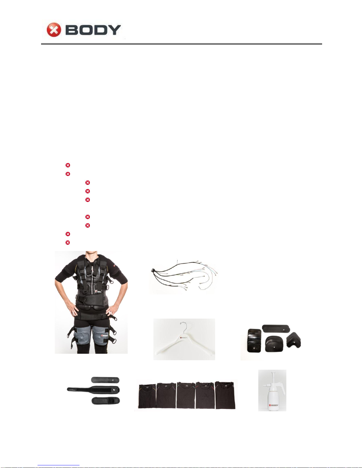
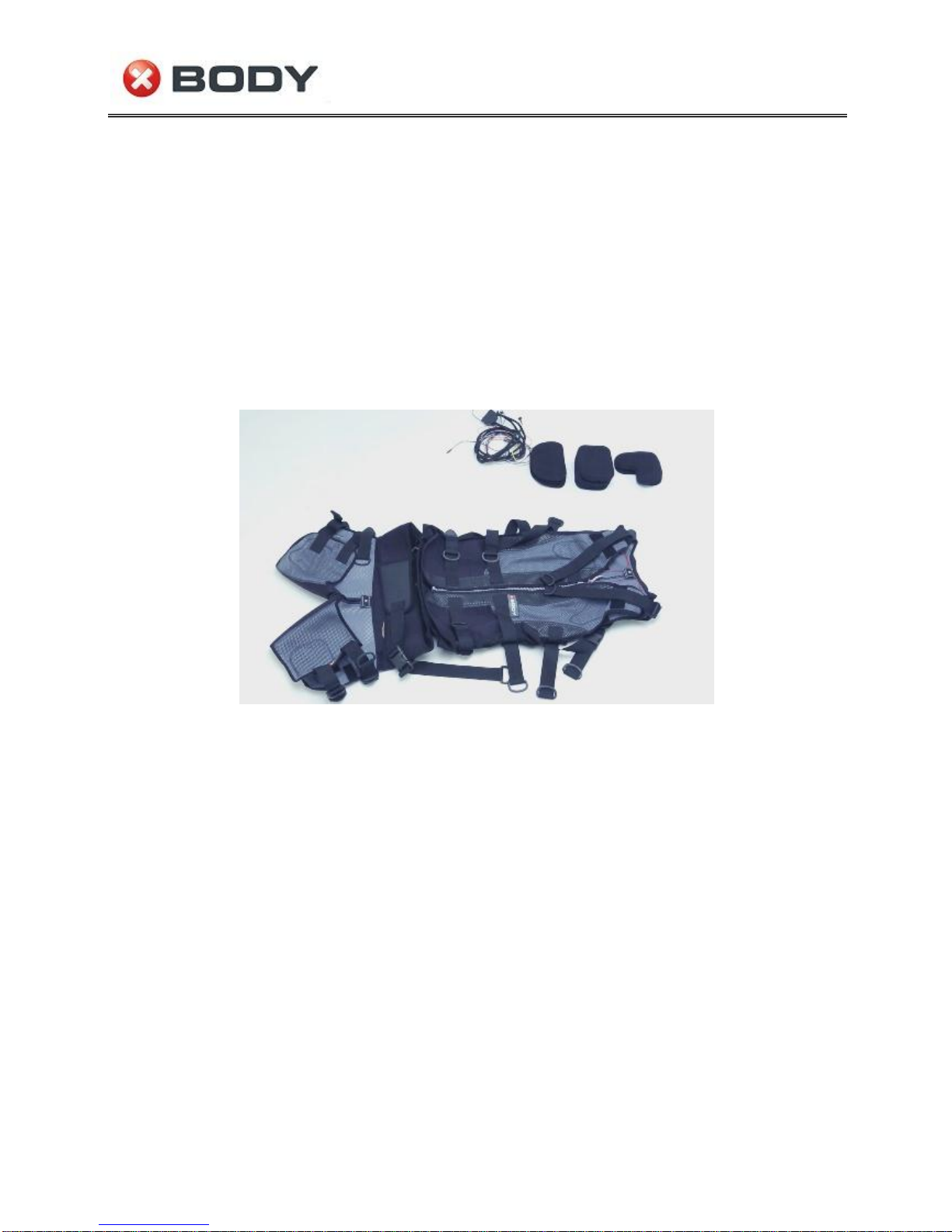
The XBody Training Suit is intended as a training and exercise appliance for muscle
conditioning in conjunction with the XBody Training® functioning on the basis of electronic
stimulations applied to various muscle groups through the use of electrodes contained in the training
suit. Follow the instructions in this manual to assure proper training and safety operation to the user.
In addition if you connect the Training Suit to an EMS device all contraindications and safety regulations
of the EMS device shall be taken into account. Be aware that improper use of this equipment can cause
injury. XBody Hungary LLC does not take the responsibility where user negligence or improper use of
the equipment has occurred.
3.1 Where never to apply the electrodes
On the head or any area of the face. The effects of stimulation of the brain are unknown.
On the neck or any area of the throat. Severe spasm of the muscles may occur and the
contractions may be strong enough to close the airway or cause difficulty in breathing.
Electrodes used for electrical stimulation should not be applied near the thorax because the
introduction of electrical current on this part of the body increases the risk of cardiac
fibrillation.
On, or in the vicinity of skin lesions or eruptions of any kind.
Over the abdominal region during menstruation periods.
On skin areas lacking of normal sensation.
It is not recommended to change the locations or modify the containment of the
electrodes within the training suit at all!
3.2 Safety regulations
Electrodes should be applied only to normal, intact, clean skin. Electrodes should not be
applied over open wounds or over swollen, infected, or inflamed areas or skin eruptions
(e.g., phlebitis, thrombophlebitis, varicose veins, etc.).
The electrodes must be connected to the muscle groups in their original place in the training
suit and they must be fixed with Velcro straps.
Electrodes must be slicked to the body with their whole surface. A partial connection can
increase the current density and it can result in pain or skin irritation.
Only undamaged electrode cables are permitted to be connected to the training suit.
Do not unplug wires or cables during training. You must stop or pause the training if you
want to do so.
Do not connect or disconnect electrodes during the training. You must stop or pause the
training if you want to do so.
3.3 Precautions
Some persons may experience skin irritation or hypersensitivity due to the electrical
stimulation.
This device should only be used with the original accessories (cable whip, etc.) and together
with an XBody EMS machine to assure safe and efficient trainings.
Never set damaged suit in operation. In case you observe damage, unusual smell or fuming
immediately inform the helpdesk of XBody Hungary LLC.
Do not try to repair or manipulate the suit anyways because the warranty is left off in case of
unintended use.

User Manual
Version: 1.1
Page: 6 / 29
The XBody Training Suit is an appliance working on the basis of electronic stimulations and
can be only used with this user manual. In case of insufficient use danger of getting injured is
obtained. The XBody Hungary LLC does not take the responsibility in case of insufficient use
of the product.
Protect the suit from extensive heat (from radiator as well).
Be aware of the risk of strangulation due to the cabling.
You should not interconnect this equipment with any other equipment that are not included
in the user manual.
3.4 Training advices
Maintenance can be done neither by the client nor the trainer, see the Maintenance section
for details.
Although the electrodes do not provide substrate to bacteria, cleaning them is advisable
after every use.
Intensity can increase when the position is changed if the electrodes are not slicked to the
body with their whole surface.
The electrodes and the underwear shall be properly wet in order to provide good
conductivity.
Skin irritation and burns beneath the electrodes have been reported with the use of
stimulation electrodes applied to the skin directly. Always use the electrodes in the
containment provided with the suit and use the underwear as well.

User Manual
Version: 1.1
Page: 7 / 29
4Preparing for the first use
The following sections will guide you through the descriptions of the suit and the steps that must be
done in order to set up everything for the training. After unpacking and checking the accessories,
limited assembly activities are required before one can assemble the suit as described below.
4.1 The training suit
A complete training suit includes electrodes, cables and armbands as well. The training suits are
designed in order to assure repeatability in electrode positioning and subsequent involvement of the
indicated muscle groups.
The suit is composed of a vest, pants and bands for legs and arms. The advantages of the suit:
The suits are unisex available in different sizes (XXS, XS, S, M, L, XL) to fit various body types.
The suit is light and easy to put on.
Adjustable side bands make the suit fit smoothly and properly.
The flexible bands do not have any negative impact on movements during training.
Bi-elastic construction ensures the retention of the suit architecture.
Electrodes can be installed easily into the suit.
The electrodes be removed and cleaned easily thus they can be reused many times.
Electrodes can be fixed securely within the suit using Velcro straps.
Suit material is completely washable.
4.2 Sizes of training suits and other accessories
The sizes of training suits are from XXS-XL depending on your needs:
Sizes (weigh)
Chest/Hip
Waist
Length of upper body
XXS (40-50 kg)
70-100 cm
60-85 cm
60-65 cm
XS (45 –60 kg)
74-104 cm
64-94 cm
62-67 cm
S (55- 80 kg)
80-110 cm
70-100 cm
63-68 cm
M (75-95 kg)
85-125 cm
76-116 cm
70-75 cm
L (90-120 kg)
100-140 cm
95-135 cm
73-78 cm
XL (110-150 kg)
110-150 cm
100-150 cm
73-78 cm
Armbands vary in sizes XS-XL. There are two different sizes of arm electrodes depending on the size of
the armbands: a short arm electrode between XS-S and a long arm electrode between M-XL.
XS
S
M
L
XL
short arm electrode
long arm electrode
36 cm
38 cm
46 cm
50 cm
60 cm

User Manual
Version: 1.1
Page: 8 / 29
Armbands and arm electrodes
Shoulder band vary in sizes S-L:
XS
S
M
L
XL
-
38 cm
46 cm
54 cm
-
One example of the optional channel’s application are shoulder electrodes. Such electrodes function
as an extension for training the muscles of the shoulder. These electrode uses an “L” formed electrode,
which can be ordered additionally from XBody Hungary LLC:
Shoulder electrodes
4.3 Preparing the suit for use
The suits are packed in the package ready to use. In case if you disassembled the suit for some reasons
(cleaning, storing, etc.) you can follow the following guide to prepare the suit for use. The suit was
designed to provide universal stimulation and training performance for both men and women. As

User Manual
Version: 1.1
Page: 9 / 29
mentioned earlier, the electrodes are easily installed within the suit and are easy to take out for
cleaning of both the suit and the electrodes. The waist belt shown below is used to fit the suit to the
client.
4.4 Cable and Electrode Installation
Securing the electrodes in the dedicated places of the suit is accomplished by Velcro fasteners.
Geometric indicators on the suit mirror the shapes of the electrodes to guide their proper installation.
As seen on the figure below the suit consists of a vest and pants. The cable whip for each suit size (XXS,
XS, S, M, L, XL) consists of four wire sets that are terminated in a single block connector to provide a
connection for the spiral cable. The two long wire sets are for the vest and the two shorter wire sets
are for the pants. There are three types of electrodes (4 “D” formed, 8 “Square” formed and 4 “L”
formed are necessary for a suit) as shown below.
Disassembled suit
To begin the installation of the cables, place the vest on the floor face up and open it on both sides to
expose the wiring paths and electrode pockets. Stitching in the suit is color coded to indicate the colors
of the wires that need to reach those areas. Unfasten the belts of the pants and open it to expose the
wiring paths and electrode pockets in it as well.
Cable installation and connection is done from the inside of the vest and pants. First prepare the cables
for installation by laying them out next the suit on a flat surface face down.
It is important to pay attention to plug the cables by following the steps shown in the following
pictures.

User Manual
Version: 1.1
Page: 10 / 29
Step 1: Install the spiral cable connector of the cable whip in the socket at the bottom of the vest as
shown in the photo.
Step 2: Lace up the longer cables from the bottom into the vest by doubling the longer cables and
pushing them through the hole provided for the wire set.

User Manual
Version: 1.1
Page: 11 / 29
Step 3:Pull the cables of the vest through the hole.
Step 4: The pants have a shorter wire set for which the same method shall be followed for lacing the
cables into the pants.

User Manual
Version: 1.1
Page: 12 / 29
Step 5: Pull the cables of the pants though the hole.
Step 6: Layout the long wire set in the interior of the vest as shown. Each wire shall end at the indicated
electrode placement area. The wires are color coded to guide proper cable installation.

User Manual
Version: 1.1
Page: 13 / 29
Step 7: Attach the cables in their designed positions with the Velcro straps.
Step 8: Use the loops provided to route and lead the wires to the corresponding electrode positions
with respect to the color coding of the wires and the stitching of the electrode placement indicators.

User Manual
Version: 1.1
Page: 14 / 29
Step 9: There are two very long wires, one on each side of the vest. Route these through their exit port
at the upper left and upper right corners of the vest.
Step 10: Use the Velcro straps to secure the short cabling in the pants in the same manner as described
for the vest.

User Manual
Version: 1.1
Page: 15 / 29
Step 11: Route the wires according to the color coding through the loops in the pants in the same
manner as described for the vest.
Step 12:The suit is properly prepared for electrode placement and connection.

User Manual
Version: 1.1
Page: 16 / 29
After the wires are prepared the electrodes can be installed. Each electrode must be put in a
containment (electrode cover) before installation. The geometry of the electrodes defines the areas
of their installation:
Eight “Square” formed electrodes are required. One for each of the four installation points in
the pants, one for each side of the belt (yellow) and two for the middle of the vest (green).
Four “D” formed electrodes are required. Two for the sides of the vest (orange) and two in
the back of the vest (white).
Four “L” formed electrodes are required. Each is for the top of the vest (red and blue).
Note: If a client reports lack of stimulation sensation to the trainer for any area of the body it usually
indicates a disconnected electrode. If such happens stop the stimulation, reconnect the electrode
(check other connections if necessary) and resume the training.
Step 13: Install the “D” formed and the “Square” formed electrodes. Connect the snap fastener of each
wire with the attachment point of the electrode on the Velcro strap side of the containment.

User Manual
Version: 1.1
Page: 17 / 29
Step 14: After the “D” formed electrode is connected to the wire with the snap fastener, place the
connected electrode over the stitching which defines the shape of the electrode and attach it to its
place with the Velcro attachment interface.
Step 15: Complete the installation of the “D” Formed electrode and repeat these steps 13-15 for each
of the “D” formed and the “Square” formed electrodes.

User Manual
Version: 1.1
Page: 18 / 29
Step 16: Install the “L” formed electrodes. Connect the snap fastener of each wire with the male
attachment point of the electrode on the Velcro strap side of the containment.
Step 17: The blue electrode shall be in a cover with three Velcro attachments points while two
connection point are defined for the red one.

User Manual
Version: 1.1
Page: 19 / 29
Step 18: The “L” formed electrode is properly placed and installed in the upper left side of the vest
while the upper right side of the vest is just prior to installation.
Step 19: All “L” formed electrodes are shown properly in place with the wires properly routed through
the loops.

User Manual
Version: 1.1
Page: 20 / 29
Step 20: The electrode for training the chest can be installed with either the regular two or a three
point connection depending upon how the trainer would like to stimulate this muscle group. Be sure
that the orientation of the placement of the electrodes must be the same on both sides. This step
shows the different placement of the “L” formed electrode.
Step 21: Everything is properly laced, and the electrodes are installed. The suit is ready for use.
Table of contents
Popular Accessories manuals by other brands

IFM
IFM Efector 200 O6E3 operating instructions

tomado
tomado TEB1301W instruction manual

ROSE DISPLAYS
ROSE DISPLAYS ADVANCETRAK WITH METAL CLIP AND V CLIP manual

LEGRAND
LEGRAND Watt Stopper CI-355 installation instructions

Balluff
Balluff BOS R254K-UUI-LH10-S4 user guide

Costway
Costway EP25110US user manual