XCS HD 104000 User manual

Xtended Camera Support, Inc.
5/2015 Rev 1.1
XCS
High Definition
Programmable Frame Line Generator
Owner’s Manual

2 | P a g e
WARNINGS AND SAFTY PRECAUTIONS
PLEASE READ BEFORE USING THIS PRODUCT
This is a precision electronic instrument and is designed to be rugged and weather resistant. It can be damaged or
may cause injury if not used properly.
Do not operate equipment without first reading this manual in its entirety. Failure to follow safety precautions could
result in component failure.
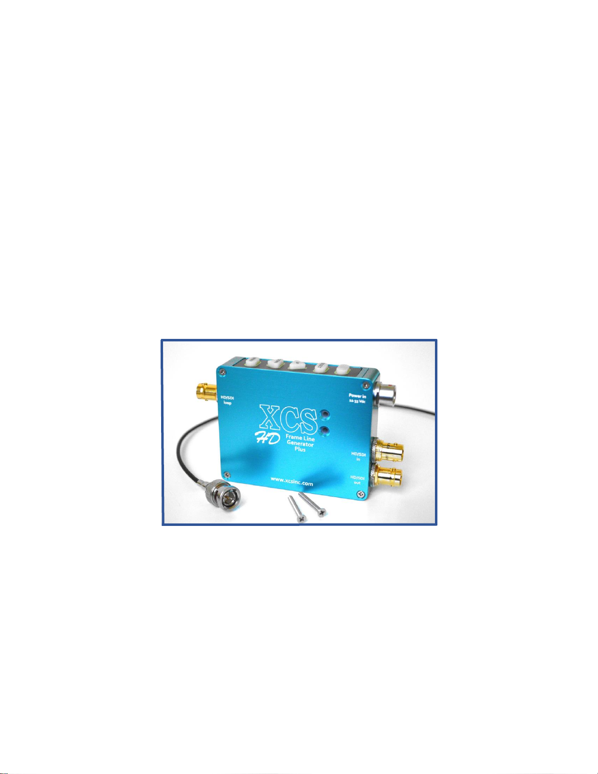
Observe the following precautions to maximize the useful life of the HD Programmable Digital Frame Liner Plus.
* Do not drop this instrument.
* Do not immerse in water.
* Do not try to remove this instrument from its housing.
* Do not plug into any power source higher than 33.00 Vdc.
* Do not connect to any Alternating Current (AC) power.
* Do not use in locations subject to hazardous gases or explosive gases.
* Do not use caustic solvents or abrasive cleaners on any part of the aluminum case, keypad or connectors.
* The unit is not waterproof. However, it is designed to be used outdoors and in damp environments.
* Be sure to observe proper electrical safety precautions in damp and wet environments.
* Be sure to cover all open video and connector ports when not in use. This will minimize any possible failures.
* There are no user serviceable parts inside.
* If mounting the Frame Liner with alternative brackets other than what XCS Inc. provides, you must seal all open
mounting screw holes to prevent water from entering.
* You should only use high definition 75 ohm BNC video cable with HD 75 ohm connectors with this device.
* The use of 50 ohm BNC connectors can permanently damage the connectors on the unit.
* Moisture condensation: If your HD Frame Liner is brought directly from below freezing to above freezing, moisture
may condense on the circuit board causing a malfunction. If moisture condensation has occurred, leave your level
for about 1 hour in the warm climate without turning it on.
To avoid moisture condensation when you bring your level in from a cold place into a warm place, put your level in
a plastic bag, remove as much air as possible and seal it tightly. Remove the Frame Liner from the bag when the
air temperature inside the plastic bag has reached the ambient room temperature (after about 1 hour).
Warranty:
Read this information before using your Programmable Digital Frame Line Generator.
The use of 50 ohm BNC connectors can permanently damage the connectors on the unit. The use of 50 ohm
connectors is considered to be misuse of the equipment and will therefore invalidate the unit’s warranty. If you are
unsure of the type of your current BNC connectors and cables and unable to find out, replace them with correct 75
ohm HD compatible cable and connectors.
Xtended Camera Support, Inc. will warranty this product for a period of one year from the original date of purchase in
its original form, to the original owner.
This includes electronics, aluminum case, connectors & keypad.
Warranty will be voided for any of the following reasons:
Any unauthorized service or repairs. Unauthorized modifications. Misuse or abuse such as, but not limited to: Impact
damage, incorrect power source, incorrect power wiring, incorrect bnc connectors, used in such a manner as it
was not intended or damage caused by acts of God.
Buyer will be responsible for all shipping costs for service and warranty repairs.
All products being returned to XCS must have an authorization number (RMA#). We can be reached at or through
www.xcsinc.com
Xtended Camera Support, Inc.
3976 Crossridge Court
Thousand Oaks, CA 91360
U.S.A.
Keep this manual in a safe location for future reference.
Do not operate this equipment without first reading this manual in its entirety. Failure to follow safety precautions in
this chapter could result in component failure.

3 | P a g e
RoHScompliant
Regulatory Information:
CAUTION
You are cautioned that any changes or modifications not expressly approved in this manual could void
your authority to operate this equipment under FCC & CE certification.
Note:
This equipment has been tested and found to comply within the limits for a Class B digital device,
pursuant to Part 15 of the FCC Rules and the EMC tests performed on the EUT and are in accordance
with EN 55103-1 and EN 55103-2 standards for emissions and immunity testing respectively.
The tests were performed to allow verification of the product to meet the EMC Directive 2004/108/EC
(Formerly 89/336/EEC).
Radiated emissions tests were performed to measure the electromagnetic emissions in the frequency
bands described in EN 55103-1 for an Environment 4 product (Environment 4 as defined by customer per
EN 55103-1 definitions). The radiated emissions measurements are used to determine whether these
emissions are below the limits expressed within the standard.
Radiated immunity testing was performed to determine the susceptibility of the EUT to the surrounding
EMI environment, by virtue of complying with the appropriate basic standard. These limits are designed to
provide reasonable protection against harmful interference in a commercial installation. This equipment
generates, uses, and can radiate radio frequency energy and, if not installed and used in accordance with
the instructions, may cause harmful interference to radio communications. However, there is no
guarantee that interference will not occur in a particular installation.
Declaration of Conformity
Trade Name: Xtended Camera Support, Inc.
Model No.: 104000
Responsible Party: Xtended Camera Support, Inc.
Address: 3976 Crossridge Court. Thousand Oaks CA. U.S.A.
This device complies with Part 15 of the FCC Rules.
This manual covers all current versions of the new High Definition Programmable Frame Liner Plus
software.
You may have a software version with limited functionality. Therefore, not all functions covered in this
manual will apply.
All HD Frame Line generators are upgradeable. To add new software functionality we will need your
device to make these changes. We have found over the years that there have been many issues with end
users trying to upgrade software in different products. Many of the issues have nothing to do with the end
user, rather computer Operating System (OS) versions and interfaces which can cause frustration for
everyone.
Send it in and your problems will be resolved, we do not offer in field reprogramming options.
XCS offers custom software for your needs. Please contact us for a quote of your vision of our design.

4 | P a g e
Thank you for your purchase of the XCS High Definition Frame Line Generator Plus.
This is the first design of its kind and the most advanced since the introduction of the XCS DUO Digital
Frame Liner over 20 years ago. We set the standard for “drift less” and “stand alone designs” in 1995 and
continue these advances for today’s new technologies. Engineered specifically for our industry from the
ground up, we offer you a wide range of user settings.
HD video will only continue advancing. The HD-Frame Line Generator Plus is already ahead of the curve
with our ability to accept a wide range of signal types 3G, 2K, HD and SDI video signals. But more
importantly, we have the ability to change the software when it becomes necessary. This ability to adapt
helps make this product one you will have for many years, unlike most HD products that are currently
designed for this niche market which seem to have a product life of 1-3 years.
Major Features:
Multiple overlay functions: Level, Frameline, Center Mark, Voltage monitoring, and more
Supports both digital SMPTE SDI, HD, 3G, 2K video inputs
Internal SMPTE Test Pattern Generator (Simultaneous HD digital & analog outputs)
Extra digital video Loop-Through output (no overlays)
Wide input voltage operational range 10.0-33.0 Vdc
Multiple case mounting orientations, vertical, front or rear facing
Reverse-circuit protected
Low power consumption
Features by Function:
FRAMELINE Features:
Single frame line positional-able over the entire video field.
Frameline generator with black, white, red, green, blue and colored zebra bar
New Line Width control
Border shading control of video image outside the frame liner
Intensity control
CENTER MARK Features:
Crosshair or center dot/box display styles
Multiple Controls: colors, size, position, and intensity
Other SYSTEM Features:
Voltage display with programmable on, off or automatic on screen display mode
Internal SMPTE Test Pattern generator in 2 discrete video signal formats -
HD/SDI 1080i60 or 1080i50
Concise on screen reporting of input video information
On screen displays of the 3 Menu pages and user selectable settings
4 pushbutton, backlit, silicone rubber keypad for a very responsive and consistent control
Automatically saves all user settings in non-volatile memory
On screen text messaging in case of video signal loss
Stand alone, compact design works with most monitors that follow SMPTE standards
Wide input voltage operational range 10.0-33.0 Vdc
Multiple case mounting orientations, vertical, horizontal, front or rear facing
Circuit protected
Low power consumption
For those who wish to jump in and are more familiar with past XCS software designs we have the quick
start method. It gives brief explanations of the functions and initial startup. But please read the entire
manual when you have time. Quick Start doesn’t cover in depth. For those who are not familiar with our
products, start here and continue through to the end.

5 | P a g e
Quick start:
Mounting your Programmable Digital Frame Liner securely. XCS has gone to great lengths to keep the
same hole mounting pattern as our previous XCS designed products. Use two screws to prevent it from
moving. Keep it flat against a rigid surface. Don’t leave the chassis or mating connectors unprotected
from damage due to cable stress or impact damage of any kind.
Remember this unit uses DC current only with a voltage input range of 10.0- 33.0 volts.
The output voltage is looped through and is always the same as the input voltage.
Do not pull current back through the Digital Frame Liner to power your sled if you have that connector
option added to the chassis.
Do not input two separate video signals in at the same time.
Standard power input connector is an 8 pin wiring for all XCS 1B 308 connectors.
See wiring diagram under Specifications at the end of this manual for pin outs.
There is no power on/off switching. Even though you may have all the graphic displays turned off, the HD-
PDL system still requires power to run the internal video distribution and keypad. If the HD-PDL is not
powered, it will not pass video. It will, however, loop power to your monitor.
Pushbuttons
5 backlit silicone rubber pushbuttons allow you to adjust all the PDL’s settings.
BLANK: Not a user button. Disabled.
SELECT: Allows you to enter (unlock) and (lock) a user programmable SETTING in a
specific PARAMETER on that MENU page.
Button is only active after you press the MENU button and times out with the on
screen menu.
UP/DOWN: Scrolls through the available PARAMETER list on each MENU page and also
scrolls through each available user programmable SETTING when you are
editing.
Button is only active after you press the MENU button and times out with the
menu.
MENU: Edit mode. Scrolls through the four editable MENU pages LEVEL, FRAMELINE
CROSSHAIR, SYSTEM. This button is always active for quick selection of your
MENU pages. The PDL memorizes and returns to the last MENU page and
PARAMETER (line item) you were editing.
We have preset all the settings including how long the MENU pages stay on screen before they time out.
In the beginning you may wish to increase the length of time the menus stay on screen so you can
familiarize yourself with all the available settings. You will find this feature under the SYSTEM MENU
page and is listed as MENU TIMEOUT with the user settings of 4, 6, 8, 10, OFF (OFF means the MENUs
stays on screen. But will time out after 30 minutes automatically).

6 | P a g e
Editing the MENU pages
To select and edit any MENU page is a simple process.
1) Select the MENU page you wish to edit by pressing the MENU button to sequentially scroll
through the three different MENU pages FRAMELINE, CENTER MARK, SYSTEM.
2) Use the UP/ DOWN buttons to scroll through the PARAMETER list of editable settings for that
page.
A curser > indicates the current PARAMETER you are selecting as it moves UP/DOWN the list.
3) Press the SELECT button to enter the editable settings. A second curser > indicates the current
setting and you are now in edit mode.
4) While in edit mode use the UP/DOWN buttons to scroll through your available settings for that
PARAMETER. Leaving your setting on screen indicates that you have selected that setting.
5) Press the SELECT button to save the setting if you wish to continue editing a different
PARAMETER on the same MENU page. Using the UP/DOWN arrows move to the next
PARAMETER you wish to edit on that same MENU page.
OR
Press the MENU button instead of SELECT if you are switching to edit a different MENU page.
OR
Let the system time out.
Any of the above three actions will automatically save your setting.
SMPTE PATTERN GENERATOR
You will not need to input a video signal to start exploring the Frame Liner. Just connect the correct power
into the HD Frame Line Generators 8 pin POWER IN connector and your monitor. The HD-PDL will
automatically generate a SMPTE color bar pattern in 50 or 60 Hz until a video signal is recognized on the
HD-BNC input connector. We have designed the Frame Liners software allowing access to all the user
programmable menus and settings with no additional video signal input.
The HD Frame Line Generators was also designed to work as a pattern generator to troubleshoot
cable, sled and transmitter issues. Having a built-in SMPTE pattern generator and true signal (VPID)
Video Payload Identification readouts can be a great time saver in isolating video issues.
BELOW ARE TWO OPTIONS FOR THE FIRST TIME USE
Option 1: Running no video signal into the HDPDL. Using the HD/SDI output bnc connected to your
monitor.
Option 2: Running an HD/SDI video signal into the HD-PDL. Output video to an HD/SDI monitor.
Option 1
Running no video signal into the HD Frame Line Generators. Using the HD/SDI output bnc connected to
your monitor.
You will notice two onscreen text boxes at start up and the SMPTE test pattern.
PDL TEST PATTERN 1080i 60 Hz
This is telling you the HD-PDL is generating a 1080i 60 Hertz video signal out. This text box will appear
on startup. A second blinking text box indicates no video signal input is recognized into the HD Frame
Line Generator and the SMPTE test pattern is being generated by the HD Frame Line Generator.
NO SDI/HD OR ANALOG VIDEO

7 | P a g e
Once a valid video input is detected, the VPID Identifier text box remains on for a fixed 10 seconds
indicating the video signal input type.
Option 2
Running an HD/SDI video signal in, output video to an HD/SDI monitor.
HD/SDI MONITOR
You are inputting an HD/SDI video signal into the HD-PDL. You will see your input video signal
on your monitor screen, the VPID data briefly (*10 seconds) and you can now start exploring the
MENU’s and settings.
Additional notes for those who use “quick start”method.
1) HD Frame Line Generator connectors:
HD/SDI IN: 2K, 3G, HD, SDI video signal types. See supported formats in the
Specifications section at the end of the manual.
HD/SDI out: 3G, 2K, HD, SDI video signal out with the HD-PDL overlays when an
HD/SDI video signal is used. With a valid SMPTE digital video
connected to the "HD/SDI IN", this connector will retransmit that same
signal with the HD-PDL overlays. With an invalid digital video input this
connector outputs a SMPTE HD 1080i Color Bar Test Pattern.
HD/SDI LOOP This connector retransmits (loops through) valid 2K, 3G, HD, SDI video
formats present at the BNC connector labeled HD/SDI in, but without
the HD-PDL overlays or menus. The output is not specified for
unrecognized input formats or under no video input conditions. Further,
the SMPTE HD 1080i Color Bar Test Pattern is NOT available at this
output under any conditions.
HDMI out: Is for future expansion and is currently not operational.
2) We have preset all the indicators to be on, but they may not be optimized for your personal
preference.
The on-screen voltage display needs special attention to be accurate when running from a
battery.
There are three SYSTEM MENU parameters that deal with the voltage display that need
special attention: VOLTs DISPLAY, VOLTs THRESHOLD and VOLTs CALIBRATE.
VOLTs DISPLAY ON/OFF/ON WHEN LOW
VOLTs THRESHOLD ADJ UP/DOWN
VOLTs CALIBRATE ADJ UP/DOWN
We recommend spending 10 minutes or so the first time to calibrate the voltage display correctly.
This will give you correct voltage indication of your “low battery warning indicator”. A voltmeter will
also be necessary to meter the voltage correctly.
Although we have preset the low battery indicator settings for you, it is an “estimated average”
based on battery manufacturer’s recommendations for low voltage draw down on battery packs.
(1.4 volts below nominal rating on lithium batteries with high current loads). This maximum
voltage draw down on a battery pack is not representative of all battery chemistries.
In addition, voltage loss over different sled manufacturers’ sled power wiring can have the
greatest effect on voltage loss in a system.
Lastly, what do you wish the “low battery indicator”to actually read? It can be set up to accurately
read different low battery conditions for different sled components or overall battery condition.

8 | P a g e
For example:
The onscreen voltage indicator can be set up to match the actual voltage at the monitor, at the
top stage, at the camera while under load, or perhaps the at the battery source.
All of these have slightly different CALIBRATION settings and test points for a truly accurate
indication on your battery status. This allows you the best possible run times without shortening
the life of your batteries or running out of power during a take.
For more explanation on the voltage display settings read pages 13/14.
3) Backlit keypad feature. The phosphorus infused rubber keypad will always have a slight
glow in the dark. This is to aid you for quick identification of the keys on the keypad. We
have also added a back light feature in each key that appears only when a key is pressed
and stays on the length of time you have programed the MENU TIMEOUT in the SYSTEM
MENU.
For a more in depth explanation of MENUs, functions, user interfaces and details on each PARAMETER
we encourage you to read on. Or keep the manual handy for reference. If you need a copy of this manual
while at remote location it can be found on our web page - www.xcsinc.com.
HD Frame Line Generator 3 MENU pages
The 3 MENU pages are FRAMELINE, CENTER MARK and SYSTEM.
On each of the MENU pages you have the PARAMETER’s list on the left side, for example FRAMELINE
on screen and you will see only your programmed setting that has been previously selected for each
PARAMETER.
For example: Viewing the FRAMELINE menu, you would see ON or OFF depending on the current
setting.
The MENU listings below show all of the possible settings for each PARAMETER:
FRAMELINE MENU SETTINGS
PARAMETER LIST
FRAMELINE ON/OFF
TOP EDGE ADJ UP/DOWN (up/down pushbuttons moves the frame line)
BOTTOM EDGE ADJ UP/DOWN (up/down pushbuttons moves the frame line)
LEFT EDGE ADJ UP/DOWN (up/down pushbuttons moves the frame line)
RIGHT EDGE ADJ UP/DOWN (up/down pushbuttons moves the frame line)
COLOR BLACK, WHITE, RED, GREEN, BLUE, ZEBRA BAR WHITE&BLACK,
WHITE&RED, WHITE&GREEN, WHITE&BLUE
LINE WIDTH 1, 2, 3, 4
INTENSITY 20-100% (20% increments adjusts the color intensity)
BORDER SHADING 0-100% (10% increments shades the background outside frame line)
EXIT MENU
CENTER MARK MENU SETTINGS
PARAMETER LIST
CENTER MARK ON/OFF
STYLE CROSSHAIR OR DOT
V POSITION ADJ UP/DOWN (up/down pushbuttons moves the center mark)
H POSITION ADJ UP/DOWN (up/down pushbuttons moves the center mark)
COLOR BLACK, RED, GREEN, BLUE, WHITE, MAGENTA, CYAN
SIZE SMALL, MEDIUM, LARGE, XLARGE, XXL
INTENSITY 0-100% (20% increments adjusts the center mark color intensity)
EXIT MENU

9 | P a g e
SYSTEM MENU SETTINGS
PARAMETER LIST
VOLTs DISPLAY ON/OFF/ON WHEN LOW
VOLTs THRESHOLD ADJ UP/DOWN (see parameter description for details)
VOLTs CALIBRATE ADJ UP/DOWN (see parameter description for details)
OUTPUT MENUs to HD/SDI
DOWN CONVERTER OFF, 3G to HD, 2K to HD (two separate optional software programs)
MENU TIMEOUT OFF, 4, 6, 8, 10
RESTORE MEMORY NO, TO FACTORY
SYSTEM VERSION SHOW
OPERATION TIME SHOW
EXIT MENU
Pushbutton Keypad Functions
Four backlit silicone rubber pushbuttons allow you to adjust all settings.
SELECT: SELECT button is only active after the MENU button is pressed.
Button has two functions:
1) Unlocks the current programmed setting by SELECTing it, so you can edit that setting.
2) Saves your user SELECTed setting so you can continue editing another PARAMETER.
For example: You wish to edit the Frame Liners, LINE WIDTH setting.
Press the MENU button until the FRAMELINE MENU page appears.
You will see a curser > indicating the last PARAMETER edited. Use the UP/DOWN
buttons to move through the list to the REACTION setting, the curser will follow.
Stop at the LINE WIDTH setting, press the SELECT button a second curser will appear >
next to the current programmed setting. Again use the UP/DOWN buttons to scroll and
select your new setting, 1, 2, 3, 4
You now have three options to save this setting into memory:
1) Let the menu time out because you are done editing.
2) Press the MENU button to edit another page.
3) Press the SELECT button that saves the setting if you are continuing to edit another
PARAMETER on that same MENU page.
UP: UP has two functions: Button is active only after MENU button is pressed.
1) Scrolls you through the list of available PARAMETERS on that MENU page. A curser >
indicates the MENU item that is currently selected.
2) When editing a SETTING, a second curser > appears indicating that you are in edit
mode and the UP button scrolls through the available user programmable settings for that
PARAMETER.
DOWN: DOWN has two functions: Button is active only after MENU button is pressed.
1) Scrolls you through the list of available PARAMETERS on that MENU page. A curser >
indicates the MENU item that is currently selected.
2) When editing a SETTING, a second curser > appears indicating that you are in edit
mode and the DOWN button scrolls through the available user programmable settings for
that PARAMETER.

10 | P a g e
MENU. Button has two functions.
1) Sequentially scrolls through the 3 editable MENU pages FRAMELINE, CROSSHAIR,
SYSTEM. This button is always active for quick selection of your MENU pages. The HD-
PDL memorizes and returns to the last MENU page and PARAMETER (line item) you
were editing in non-edit mode when you recall the MENU after it has timed out.
2) Exits the on screen Menu page. Even when the System Menu Time Out settings is set to
the OFF position.
Editing the MENU pages
To select and edit any MENU page is a simple process.
1) Select the MENU page you wish to edit by pressing the MENU button once per MENU page to
sequentially scroll through the different pages FRAME LINE, CENTER MARK, SYSTEM.
2) Use the UP/ DOWN buttons to scroll the editable PARAMETER list on that page.
A curser > indicates the current PARAMETER you are editing as it moves UP/DOWN the list
indicating your selection with each press of the button.
3) Press the SELECT button to enter the editable settings. A second curser > indicates the
current setting and you are in edit mode.
4) While in edit mode, use the UP/DOWN buttons to scroll through your available settings for that
PARAMETER. Leaving your setting on screen indicates that you have selected that setting.
5) Press the SELECT button to save the setting if you wish to continue editing a different
PARAMETER on the same MENU page. Using the UP/DOWN arrows to move to the next
PARAMETER you wish to edit.
OR
Press the MENU button instead of SELECT if you are continuing to edit a different MENU page.
OR
Let the MENU time out.
Didn’t like your last setting? Simply press the MENU button after the menus have timed out and you will
return to the last edited MENU page and the last PARAMETER selected in non-edit mode.
This allows for quick adjustments of your last setting.
All the settings are stored in nonvolatile memory even after the unit is powered down. There are no
internal batteries to worry about changing. This has been an XCS standard for all our product designs.

11 | P a g e
FRAMELINE MENU SETTINGS
Factory Preset: ON, Zebra bar White & Blue, Width 1
The FRAMELINE parameter settings are independent for both HD-SDI and analog. Both settings are
independently memorized and stored in the HD-PDL memory for immediate recall of your setting. So you
can have a red frame line in HD-SDI and a black & white zebra bar in analog.
The single frame line has no preset aspect ratios. You can adjust it over the entire height and width of the
video field up to 2 pixels from all edges.
> FRAMELINE ON/OFF
TOP EDGE ADJ UP/DOWN
BOTTOM EDGE ADJ UP/DOWN
LEFT EDGE ADJ UP/DOWN
RIGHT EDGE ADJ UP/DOWN
COLOR BLACK, WHITE, RED, GREEN, BLUE, ZEBRA BAR WHITE&BLACK,
WHITE&RED, WHITE&GREEN, WHITE&BLUE
LINE WIDTH 1, 2, 3, 4
INTENSITY 20-100% (20% increments adjusts the frame line color intensity)
BORDER SHADING 0-100% (10% increments shades the background outside frame line)
EXIT MENU
FRAMELINE: OFF, ON. Frame line on, off control.
TOP EDGE: ADJ UP/DOWN.Up/down pushbuttons moves the frame line up and down.
BOTTOM EDGE: ADJ UP/DOWN.Up/down pushbuttons moves the frame line up and down.
LEFT EDGE: ADJ UP/DOWN.Up/down pushbuttons moves the frameline left and right.
RIGHT EDGE: ADJ UP/DOWN.Up/down pushbuttons moves the frameline left and right.
COLOR: BLACK, WHITE, RED, GREEN, BLUE, ZEBRA BAR WHITE&BLACK, WHITE&RED,
WHITE&GREEN, WHITE&BLUE
Adjusts the color of your FRAMELINE. Adjusts the color of your indicator. You can also modify the
selected color or shading by adjusting the color INTENSTY settings.
LINE WIDTH: 1, 2, 3, 4 Adjusts the frame line width.
INTENSITY: 20-100%.Sets the color intensity of the frame line display. Adjusts intensity in 20%
increments.This will change the shade of the colored level display to different shades of that selected
color.
BORDER SHADING: 0-100%. Adjust the shading outside the single frame line in 10% increments.
0% represents no video (opaque), 100% no shading at all (transparent).
EXIT MENU: Allows you to select it to exit the MENU pages or you can allow it to “time out”.
CENTER MARK MENU SETTINGS
Factory Preset: ON, Crosshair, Red, Large
>CENTER MARK ON/OFF
STYLE CROSSHAIR OR CENTER DOT
V POSITION ADJ UP/DOWN (up/down pushbuttons moves the frameline)
H POSITION ADJ UP/DOWN (up/down pushbuttons moves the frameline)
COLOR BLACK, RED, GREEN, BLUE, WHITE, MAGENTA, CYAN
SIZE SMALL, MEDIUM, LARGE, XLARGE, XXL
INTENSITY 0-100% (10% increments)
EXIT MENU

12 | P a g e
CENTER MARK: ON, OFF.Turns ON/OFF the center mark.
STYLE: CROSSHAIR OR DOT.Selectable Crosshair or Dot on screen.
V POSITION: ADJ UP/DOWN.Adjusts position of the center mark using the up & down buttons.
H POSITION: ADJ UP/DOWN.Adjusts position of the center mark using the up & down buttons.
COLOR: BLACK, RED, GREEN, BLUE, WHITE, MAGENTA, CYAN. Selects the color of the
crosshair or dot display.
SIZE: SMALL, MEDIUM, LARGE, XLARGE, XXL. Allows size adjustment of the center
mark. The center DOT will turn into a center open frame box as it gets larger to allowing the video image
to show through.
INTENSITY: 20-100%.Sets the color intensity of the center dot or cross hair display. Adjusts
intensity in 20% increments. This will change the shade of the colored level display to different shades of
that selected color.
EXIT MENU: Allows you to select it to exit the MENU pages or you can allow it to “time out”.
SYSTEM MENU SETTINGS
Factory Preset: Voltage display ON, Output Menus to SDI, Down Converter OFF, PDL KEYPAD UP
>VOLTs DISPLAY ON, OFF, ON WHEN LOW
VOLTs THRESHOLD ADJ UP/DOWN
VOLTs CALIBRATE ADJ UP/DOWN
ANALOG OUTPUT NTSC:COLOR, NTSC:B/W, PAL:B/W, PAL:COLOR
OUTPUT MENUs to SDI/HD, ANALOG
DOWN CONVERTER OFF, 3G to HD, 2K to HD (two separate optional software programs)
MENU TIMEOUT OFF, 4, 6, 8, 10
RESTORE MEMORY NO, FACTORY
SYSTEM VERSION SHOW
OPERATION TIME SHOW
EXIT MENU
VOLTAGE DISPLAY: ON, OFF, ON WHEN LOW (automatic)
Factory Preset: ON
User programmable low battery display will indicate battery voltage in real time with a 3 ½ digital readout.
It appears on the lower right hand side of your monitor screen with three user programmable display
options OFF, ON, ON WHEN LOW.
Data box, 3 ½ digit indicator:Displays current battery voltage. 10.0 v to 34.0 v. Black box with
two different colors of text helps enforce battery status. Green text indicates the battery condition
is good and 0.6 volts above your programmed VOLTs THRESHOLD setting.
Yellow text indicates your voltage has dropped to 0.5 volts above your low battery VOLTs
THRESHOLD setting and will also blink once every second.
When your programmed VOLTs THRESHOLD is reached the indicator will blink twice a second.
ON: Data box is always on screen indicating voltage.
OFF: Data box display will not appear at all.
ON WHEN LOW: Indicator is hidden until the batteries fall within 0.5 volts of your programmed
low battery THRESHOLD setting. At that time your data box will appear on screen, yellow text
and will blink once a second.

13 | P a g e
VOLTs THRESHOLD: ADJ UP/DOWN (On screen text box will appear)
Factory Preset: 12.5 volts
Under this parameter you are able to program a voltage point at which you would like to run your batteries
down to at their lowest voltage point. We recommend you consult your battery pack supplier or battery
handbook to determine the lowest voltage your battery chemistry can be safely run, given your current
draw. It varies between battery chemistry. Also be aware if you run battery voltage too low under high
current draws and then “Hot Swapping” battery packs, they may not have the capacity during this
swapping to keep a camera powered. Battery manufacturers do not take this into account when
specifying their low battery cutout voltages. You should take into account your voltage loss through your
sled wiring.
Programming the VOLTs THRESHOLD setting:
When you enter this editable menu setting a text box will appear in addition to the SYSTEM MENU on the
upper left side displaying:
ADJUST THE THRESHOLD THAT IS DISPLAYED IN THE VOLTAGE FIELD..,
This is directing you to use the voltage box on the lower right to set your LOW BATTERY THRESHOLD
voltage. Example 13.2At this point, the value displayed is your threshold setting NOT the actual battery
voltage. Use the UP/DOWN arrow buttons to make this adjustment. Each press of the arrow button will
change the voltage settings in 0.1 volt increments.
If you run both 12 and 24 volt cameras you can set up the low battery indication for both 12 and
24 volt ranges. You will need 24 volts into the HD Frame Liner to set this higher voltage range. Most
operators will not be setting this upper range because they do not run the HD Frame Liner off these
higher voltages 19-33.00 volts.
If you set up the 12 volt low threshold indication only, it will automatically double this setting when you go
to 24 volt input into the HD Frame Liner, or are using 24 volt batteries into the HD Frame Liner.
For example: Running it a Steadicam
Voltage display set to be always ON screen.
You have programed the low battery THRESHOLD indicator on 12 volt cameras to 13.2 volts.
When the battery drops to 13.7 volts the indicator will switch from Green text to Yellow and blink
once a second.
When the battery reaches 13.2volts your set THRESHOLD the indicator will blink at twice a
second.
If you switch to 24 volt mode without programming the 24 volt THRESHOLD range indication:
When the battery reaches 27.4 volts the indicator will switch from Green text to Yellow and blink
once a second.
When the battery reaches 26.9volts the indicator will blink twice a second.
VOLTs CALIBRATE: ADJ UP/DOWN (On screen text box will appear)
Factory Preset: Vin- 16.0 Vdc
Under this parameter you will be setting the true battery voltage reading of the batteries at a specific point
on the sled. This triggers when the low battery indicator appears on the monitor screen if in ON WHEN
LOW mode.
For a true indication of your actual battery voltage it is important to get an accurate reading of the voltage
using a volt meter and knowing where you actually wish to monitor the voltage. Some operators are
interested in the voltage at the camera if they power the camera. Others may only be interested in the
LCD monitor battery voltage and wish to indicate that battery. While others wish to monitor all batteries at
the source, so you have options.
When measuring voltage with the volt meter, don’t be surprised to see a voltage drop of 1.0-1.5 volts from
the battery on the bottom of the sled to the top stage on some sled wiring under current loads. It is
important to know this voltage loss for a true indication of the camera battery status if that is what you
wish to read.
It is not necessary to have hot batteries on the sled in order to make these settings.

14 | P a g e
Programming the VOLTs CALIBRATE
When you SELECT to edit the VOLTs CALIBRATE menu setting, a text box will appear in addition to the
SYSTEM MENU on the upper left side displaying:
ADJUST THE VOLTAGE DISPLAYED AS REQUIRED TO CALIBRATE.
This is directing you to use the UP/DOWN pushbuttons and voltage box on the lower right to set the
voltage. Example 15.3. At this point the value displayed should be adjusted to match the actual voltage of
choice. Whether it be battery source as measured with a volt meter, camera power input measured or
reported by the camera, etc.
Example: Using it on a Steadicam and monitoring battery voltage at the camera for your low battery
VOLTs CALIBRATION
You have two or three 14.4V battery blocks on the sled.
The sled you are running is in 12 volt mode and all components are powered.
The voltage readout on the ALEXA or RED is reading 15.3.
This 15.3 volt setting is what you use for the VOLTs CALIBRATE setting.
Repeat the process for 24 volt cameras with your sled in 24 volt mode and the HD-PDL receiving 24
volts. If you don’t, when you run 24 volt systems the HD-PDL will automatically double the setting you
programmed in 12 volt mode. Using the example from above it will automatically use 30.6 volts as your
true voltage reading at the camera.
Or
You can put your sled into 24 volt mode and read the voltage readout on the camera LCD. If it states for
example 28.6 volts, you would set the VOLT’s CALIBRATE to 14.3 if you are running the PDL in 12 volt
mode while the camera is in 24 volt mode.
*Note. If you are monitoring the battery voltage at the camera it’s important to note that the HD-PDL is running off the
same batteries and not an isolated battery. Otherwise it would read only the isolated monitor battery.
OUTPUT MENUsTO: HDSDI
Preset to: HD/SDI bnc.
A multi-functional control setting. This setting directs the MENU pages and all HD-PDL generated
graphics to be displayed on either the HDSDI output BNC connector.
The SMPTE pattern generator is always active on both HD-SDI and analog outputs. The analog output is
a down converted HD-SDI signal.
DOWN CONVERTER: OFF, 3G to HD, 2K to HD (OPTIONAL SOFTWARE PACKAGE)
Two separate and distinct optional software packages that can be added.
OFF setting passes the 3G & 2K through the HDPDL with graphics in its native resolution. You must have
a 3GA, 2K compatible monitor to view both of these signals.
A) 3G to HD down-converts the double clock 3G image to function with non 3G compliant
monitors.
B) 2K to HD down-converts the 2048 image to function with non 2K compliant monitors.
This parameter will be present on all HDPDL’s but is not functional if the optional software is not
installed.
MENU TIMEOUT: 4, 6, 8, 10, OFF.
Preset to: 4 seconds
Programmable time delay in seconds between the last pushbutton pressed and the time it takes for the
MENU list to disappear. In OFF mode the on screen text will remain on for 30 minutes and will
automatically timeout. This will also time out your backlit keypad.
RESTORE MEMORY: NO, TO FACTORY.
Allows a FACTORY reset of the HD- PDL. This will bring all HD-PDL values back to factory presets.

15 | P a g e
SYSTEM VERSIONS:
Displays software Serial Number, Board Revision, and Firmware version numbers when you press the
SELECT button.
A security feature XCS started over 18 years ago by coding the serial number in the memory chip so it
can’t be removed. This makes the unit easier to trace in case it is lost or stolen.
OPERATION TIME: SHOW.
Displays the number of hours the PDL has be operational when selected. It is displayed in the text box on
screen
EXIT MENU: Allows you to select it to exit the MENU pages or you can allow it to “time out”.
ON SCREEN SMPTE PATTERN GENERATOR:
A SMPTE test pattern generator will automatically appear on screen if no input video is
recognized on any of the input connectors. It will automatically turn off when an input video signal is
recognized.
The Test Pattern is an HD 1080 i 60 Hz (or 50 Hz) signal on the HD/SDI output BNC connector.
When the pattern generator appears on screen two different text boxes will appear:
1) PDL TEST PATTERN 1080 i 60Hz This indicates that the HD Frame Liner is generating the
currently displayed test pattern; and whether it is a 60 or 50Hz 1080i HD format.
2) NO HD/SDI VIDEO This indicates no valid video input signal is recognized.
The Test Pattern generator was designed to be used as a troubleshooting tool and warning indicator due
to the loss of video into the HD Frame Liner. It also allows setting up the HD Frame Liner without an
input video source. The HD SMPTE Test Pattern generator output can drive any HD/SDI monitor,
transmitter or cable to trouble shoot video issues in your sled and video transmitter.
VIDEO IDENTIFICATION Text Box and VPID
The video identification text box will appear for 10 seconds when the video signal is first recognized and
can be very useful in trouble shooting signal related issues. It correctly identifies and reports important
input video characteristics: pixel resolution, video scan type (progressive, interlace, PsF), vertical field
rate, and the particular video standard (SDI, HD, 3G, 2K). Text box examples:
1920 x 1080 p 60Hz 3G 1920 x 1080 p 30Hz HD 1920 x 1080 i 60Hz HD 1920 x1080 PsF 60Hz HD
The HD Frame Liner also decodes the embedded SMPTE-352M Video Payload Identifier Data (VPID)
and correctly distinguishes between 1080 PsF and 1080 i formats which are otherwise indistinguishable.
Many devices incorrectly identify 1080 PsF formats as 1080 i. If the SMPTE VPID data is missing, the
HD Frame Liner reports this by displaying "i/PsF". For example: 1920 x 1080 i/PsF 60Hz HD.
TEXT MESSAGE BOXES:
Various on screen text box messages to help navigate, inform & warn you.
TEST PATTERN 1080 i 60 Hz Example of 1 of 4 HD-PDL’s test pattern.
NO HD/SDI No video input recognized.
1920 x 1080 p 23.98Hz VPID data reported. One for each signal type and rate.
1920 x 1080 i / PsF 60 Hz This would be an example of a video identification text box when the HD
Frame Liner was not able to differentiate between 1080 i 60Hz and 1080 PsF 30Hz because no VPID
data is present in the video input stream.
ADJUST THE VOLTAGE DISPLAYED AS REQUIRED TO CALIBRATE Refer to pg.14 for setting.

16 | P a g e
ADJUST THE THRESHOLD THAT IS DISPLAYED IN THE VOLTAGE FIELD Refer to pg.13 for setting.
27.0 Example of voltage display of battery status. Color will vary depending on battery status.
SYSTEM MENU SETTINGS Indicates which connector the MENUs are
OUTPUT MENU’s to HD/ SDI output on. HD/SDI bnc..
Specifications:
Specifications may change without notice.
Case size: 2.8” x 3.5” x .875”, 71.1mm x 88.9mm x 22.1mm
Case material: .063” Aluminum
Keypad: 5 pushbutton back lit, phosphorus infused silicone rubber
Weight: 5.7 ounces / 162.6g
Power: 10.0-33.0 Vdc input range
Power consumption: 4 watts
Circuit protection: Reverse polarity protected
Operating & Storage Temperature:-25C to 65C
Input video signal types:
Digital Video: See supported formats in Table below.
SMPTE 4:2:2, 10-bit 2K, 3G, and HD
SMPTE 4:2:2, 8-bit SDI
800mVpp, 75Ω internal termination
Warning: Double 75Ω termination or improper signal splitting
may result in signal corruption or loss.
.
Output video signal types: Same as above. All require proper 75Ω termination.
Input Connectors:
POWER IN EHG/EGG-1B-308 8 pin.
Power inputs (see pin definitions below).
HD/SDI IN BNC
SMPTE digital video input.
Output Connectors:
Optional POWER OUT EHG/EGG-1B-308 8 pin.
Note: 44 Watt maximum loop through on the 1B-308 connectors.
Maximum LCD/CRT monitor current load would be 3 amps at 14.4 volts
(44 watts) on the power wires through using a 24” long monitor cable
with a minimum 24 Awg copper wire.
HD/SDI out BNC.
SMPTE digital video output with or without overlays, or HD 1080i
SMPTE Test Pattern output when there is no video input.
HD/SDI Loop BNC.
SMPTE digital video output without overlays only when a digital video
input is present.
Note: The SMPTE Test Pattern is NOT available on this output.
HDMI Micro HDMI (Type D).
Note: Currently not functional, future expansion

17 | P a g e
Table 1: Supported Input SMPTE Digital Formats
Other formats may work but are untested.
SDI 720 x 487 i 59.94 Hz
SDI 720 x 576 i 50 Hz
HD 1280 x 720 p 23.98, 24, 25, 29.97, 30, 50, 59.94, 60 Hz
HD 1920 x 1080 i 50, 59.94, 60 Hz
HD 1920 x 1080 p 23.98, 24, 25, 29.97, 30 Hz
HD 1920 x 1080 PsF 23.98, 24, 25, 29.97, 30 Hz
3G 1920 x 1080 p 50, 59.94, 60 Hz
2K 2048 x 1080 p 47.95, 48, 50, 59.94, 60 Hz
Note: Only Single-Link (Mode A) formats are supported.
Pin Definitions: ("Loop through" means the pins of both "IN" & "OUT" connectors are directly connected.)
POWER IN" (EHG/EGG-1B-308)
Pin Definition
1 Power GROUND INPUT, looped through
2 +POWER INPUT: +10.0 to +33.0 Vdc power positive, looped through
3 Not Connected (NC)
4 NC
5 NC
6 NC
7 NC
8 NC
Optional POWER OUT (EHG/EGG-1B-308)
Pin Definition
1 looped through Power GROUND OUTPUT
2lopped through +POWER OUTPUT
3 Not Connected (NC)
4 NC
5 NC
6 NC
7 NC
8 NC
Table of contents
Popular Portable Generator manuals by other brands

Kohler
Kohler 65EOZDJ installation instructions

Thermo King
Thermo King TriPac 3 Operator's manual

ABB
ABB EBN853 operating instructions

Mase Generators
Mase Generators Marine IS 9.5 installation manual

Mosa
Mosa GE 4000 LDS/GS USE AND MAINTENANCE MANUAL SPARE PARTS CATALOGS

Champion
Champion CPG5500E2DF-J manual

Leader Electronics Corp.
Leader Electronics Corp. LT 416 instruction manual

Kohler
Kohler 14RCAL Installation

Mosa
Mosa GE 7554 YDE-L Use and maintenance manual

SIGLENT
SIGLENT SSG6080A Series Programming guide

ECS
ECS AdvancedIQ AG-675 Installation & operation manual

Powermate
Powermate PM0645500 Operator's manual